Floors & Ceilings
SRS Ulimate Acoustic Solutions for Floors and Ceilings - Sound ...
SRS Ulimate Acoustic Solutions for Floors and Ceilings - Sound ...

Create successful ePaper yourself
Turn your PDF publications into a flip-book with our unique Google optimized e-Paper software.
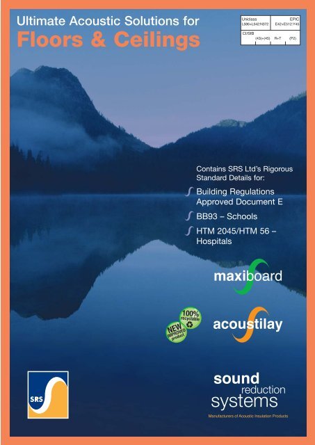
Ultimate Acoustic Solutions for<br />
<strong>Floors</strong> & <strong>Ceilings</strong><br />
Uniclass<br />
L586+L542:N372<br />
EPIC<br />
E42+E512:Y45<br />
CI/SfB<br />
(43)+(45) R+T (P2)<br />
Contains SRS Ltd’s Rigorous<br />
Standard Details for:<br />
Building Regulations<br />
Approved Document E<br />
BB93 – Schools<br />
HTM 2045/HTM 56 –<br />
Hospitals<br />
NEW<br />
IMPROVED<br />
product<br />
100%<br />
recyclable
Introduction<br />
Introduction<br />
Sound Reduction Systems Ltd. (SRS) manufacture<br />
acoustic insulation and absorption products for use in<br />
domestic and commercial buildings. Over 25 years<br />
experience in the building acoustics industry ensures<br />
that our team of qualified acousticians can offer<br />
honest, practical advice and effective solutions to any<br />
acoustic challenge.<br />
SRS Ltd’s expertise includes compliance with current<br />
building regulations, in particular with Part E in<br />
housing, HTM 2045/HTM 56 in hospitals and Building<br />
Bulletin 93 in schools. This brochure details SRS Ltd’s<br />
range of solutions to these standards.<br />
Navigation symbols<br />
Contents<br />
Introduction . . . . . . . . . . . . . . . . . . . . . . . . . . . . . 2<br />
The Standards . . . . . . . . . . . . . . . . . . . . . . . . . . . 4<br />
Approved Document E . . . . . . . . . . . . . . . . . . . .4<br />
Approved Document E Specification Generator . . .5<br />
BB93 - Acoustic Standards for Schools . . . . . . . .6<br />
HTM56/2045 - Acoustic Standards for Hospitals . .7<br />
Acoustic performance . . . . . . . . . . . . . . . . . . . . . . 8<br />
Maxi 30 Ceiling . . . . . . . . . . . . . . . . . . . . . . . . . .8<br />
Maxi 60 Ceiling . . . . . . . . . . . . . . . . . . . . . . . . . .9<br />
Maxi ceiling - below existing plasterboard . . . . . .10<br />
Maxi ceiling - below beam & block . . . . . . . . . . .11<br />
Acoustilay - above lath & plaster ceiling . . . . . . .12<br />
ACOUSTIC<br />
DATA<br />
FIRE<br />
DATA<br />
INSTALLATION<br />
GUIDANCE<br />
Acoustilay - above plasterboard ceiling . . . . . . . .13<br />
Throughout this brochure you notice these navigation<br />
symbols, followed by a page number. These point you<br />
to corresponding data within the document - follow the<br />
symbols to transfer quickly between acoustic data,<br />
fire data and installation guidance.<br />
Installation Guide . . . . . . . . . . . . . . . . . . . . . . . . 14<br />
Maxi 60 Ceiling . . . . . . . . . . . . . . . . . . . . . . . . .14<br />
Maxi 30 Ceiling . . . . . . . . . . . . . . . . . . . . . . . . .15<br />
Maxi ceiling - below existing plasterboard . . . . . .16<br />
Maxi ceiling - below beam & block . . . . . . . . . . .17<br />
Useful Contact Details:-<br />
Technical and General Enquiries<br />
Tel/Fax: 01204 380074 / 380957<br />
Email: info@soundreduction.co.uk<br />
Maxiboard on floors . . . . . . . . . . . . . . . . . . . . . .18<br />
Acoustilay . . . . . . . . . . . . . . . . . . . . . . . . . . . . .19<br />
Physical Properties & Accessories . . . . . . . . . . . . 22<br />
Acoustilay . . . . . . . . . . . . . . . . . . . . . . . . . . . . .22<br />
Maxiboard . . . . . . . . . . . . . . . . . . . . . . . . . . . .24<br />
Additional Information & Important Notes . . . . . . . 25<br />
(Including finishing and plastering details, rsj details,<br />
downlighter details and information on acoustic testing)<br />
2
Introduction<br />
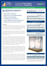
Noise Control<br />
To effectively control noise, it is important to understand the<br />
difference between sound absorption and sound insulation.<br />
Sound absorption relates to the amount of echo and<br />
reverberation within a room and its effect on sound quality and<br />
audibility. Sound insulation, on the other hand, relates to the<br />
actual attenuation of sound travelling from one area to another<br />
through a separating wall, floor or ceiling.<br />
Sound transmission in buildings results from both airborne and<br />
impact noise sources.<br />
Airborne sound is generated from sources such as human voices,<br />
Hi Fi’s or TV sets, and travels through the air into the structure of<br />
a building.<br />
Impact sound is the result of physical excitation of the structure<br />
of a floor from impacts such as footfall and dropped items.<br />
The acoustic integrity of any separating structure can be<br />
compromised by flanking. Flanking sound occurs when there is<br />
an alternative path that sound can use to bypass an insulating<br />
element, this could be due to factors such as service penetrations<br />
and hidden cavities. Possible flanking paths must be identified<br />
and eliminated before effective sound insulation can be achieved.<br />
The Regulations<br />
Poor acoustic separation can lead to disturbance between<br />
residential dwellings, discomfort or lack of privacy in hospitals<br />
and in schools it leads to an environment which is not<br />
conducive to teaching or learning. The following regulations<br />
have been introduced to ensure that New Build and converted<br />
dwellings, schools and hospitals have an adequate level of<br />
acoustic separation.<br />
Building Regulations Part E<br />
Building Bulletin 93<br />
HTM 2045/HTM 56<br />
The Testing Process<br />
Under the current Building Regulations, introduced in July 2003,<br />
acoustic testing is required to demonstrate compliance with the<br />
insulation standards for all conversions and for new build projects<br />
if not constructed using Robust Details. The tests will need to be<br />
carried out by an independent, accredited acoustic consultant<br />
and this can be arranged through our network of distributors. An<br />
additional list of suitable companies can be found on the internet<br />
at www.association-of-noise-consultants.co.uk.<br />
Sound Reduction Systems Ltd technical team are also able to<br />
carry out the tests to the appropriate standards where required,<br />
although as a manufacturer, we cannot claim the status of an<br />
independent consultant. If you are unable to find a solution for<br />
your specific acoustic insulation problem or require further advice,<br />
please contact our experienced technical team on 01204 380074<br />
or email info@soundreduction.co.uk where an advisor will be<br />
happy to assist.<br />
The Airborne Test (on site)<br />
The airborne test is designed to measure the difference in sound<br />
level between two rooms with a large, steady sound source<br />
operating in one of the rooms. The result is known as the<br />
weighted Standardised Level Difference, or D nTw , which is<br />
essentially the difference in sound level between the two rooms,<br />
adjusted to take account of the reverberation in the receiving<br />
room. The result is adjusted again by the addition of the spectrum<br />
adaptation term, or C tr , which is intended to place more emphasis<br />
on low frequency sound, such as that produced by the<br />
subwoofer in a modern home cinema or hi-fi system. Since this<br />
test measures the difference in sound level between the rooms,<br />
then the higher the figure, the better the insulation.<br />
The Impact Test<br />
The impact test measures the sound level downstairs when a<br />
standard tapping machine is operating upstairs. This is intended<br />
to replicate noise such as footsteps and moving furniture, that<br />
travels through the separating floor. The result is known as the<br />
weighted Standardised Impact Sound Pressure Level, or L nTw and<br />
the lower the sound pressure level downstairs, the better the<br />
insulation. In the case of the impact test, no additional adaptation<br />
term is used.<br />
It is likely that the floor finish will be decided after the impact test<br />
has been performed. It is, therefore, prudent to perform the test<br />
on a ‘worst case scenario’ basis. The Association of Noise<br />
Consultants advise that a rigid board, which need be no more<br />
than 50% larger than the base of the tapping machine, be placed<br />
on top of resilient floor coverings prior to testing. This way, the<br />
acoustic consultant can be satisfied that the Acoustilay will<br />
comply with Document E, regardless of floor finish. Building<br />
Control bodies often require that the Acoustilay is bonded to the<br />
floor, to reduce the risk of its removal after testing.<br />
3
Document E<br />
Residential : Building Regulations Part E – Resistance to the Passage of Sound<br />
Acoustic noise control in buildings for residential use is regulated<br />
using Approved Document E. This Building Regulation now applies<br />
to any kind of building used as a dwelling, including houses and<br />
apartments; and rooms for residential purposes, such as students<br />
and nurses accommodation, nursing homes and hotels. It also<br />
applies to dwellings that have been created as a result of a<br />
conversion or material change of use.<br />
The aim of the regulation is to protect residents from the noise of<br />
activities in other rooms or adjoining properties. This has been<br />
highlighted as a major cause of tension between residents. The<br />
acoustic requirements are shown below in tables 1.1a & 1.1b:-<br />
Table 1.1a: Dwelling-houses and flats - performance standards for separating floors, and stairs that have a separating function.<br />
Airborne sound insulation Impact sound insulation<br />
D nT,w + C tr dB<br />
L’ nT,w dB<br />
(Minimum Values)<br />
(Maximum Values)<br />
Purpose built dwelling-houses or flats<br />
<strong>Floors</strong> and Stairs 45 62<br />
Dwelling-houses or flats formed by material change of use<br />
<strong>Floors</strong> and Stairs 43 64<br />
Table 1.1b: Rooms for residential purposes - performance standards for separating floors, and stairs that have a separating function.<br />
Airborne sound insulation Impact sound insulation<br />
D nT,w + C tr dB<br />
L’ nT,w dB<br />
(Minimum Values)<br />
(Maximum Values)<br />
Purpose built rooms for residential purposes<br />
<strong>Floors</strong> and Stairs 45 62<br />
Rooms for residential purposes formed by material change of use<br />
<strong>Floors</strong> and Stairs 43 64<br />
In addition to these targets, separating structures within a dwelling<br />
must also meet or exceed the following targets as set out in table<br />
1.1c. It is anticipated that these standards should improve the level<br />
of privacy within a dwelling.<br />
Table 1.1c: laboratory values for new internal floors within: dwelling-houses, flats and rooms for residential purposes, whether purpose built or formed<br />
by material change of use.<br />
Airborne sound insulation<br />
R w dB<br />
(Minimum Values)<br />
<strong>Floors</strong> 40<br />
4
Specification Generator<br />
Approved Document E<br />
Conversion<br />
TYPE OF FLOOR<br />
Separating<br />
Floor<br />
EXISTING FLOOR<br />
STRUCTURE<br />
Timber<br />
EXISTING CEILING<br />
STRUCTURE<br />
12.5mm<br />
plasterboard<br />
SRS SOLUTION<br />
Remove plasterboard<br />
then use Maxi 60 ceiling*<br />
ACOUSTIC<br />
DATA<br />
INSTALLATION<br />
GUIDANCE<br />
9<br />
14<br />
FIRE<br />
DATA 24<br />
225mm joists, lath and<br />
plaster ceiling or<br />
27.5mm plasterboard<br />
off resilient bars<br />
Acoustilay 15<br />
ACOUSTIC<br />
DATA<br />
12,<br />
13<br />
INSTALLATION<br />
GUIDANCE 19<br />
FIRE<br />
DATA **<br />
225mm joists, lath and<br />
plaster ceiling or 2<br />
layers of plasterboard<br />
Dropped Maxi 30<br />
ceiling*<br />
ACOUSTIC<br />
DATA<br />
INSTALLATION<br />
GUIDANCE<br />
10<br />
16<br />
FIRE<br />
DATA 24<br />
No ceiling<br />
Maxi 60<br />
ceiling*<br />
ACOUSTIC<br />
DATA<br />
INSTALLATION<br />
9 GUIDANCE 14<br />
FIRE<br />
DATA 24<br />
Acoustilay over<br />
resiliently mounted<br />
plasterboard ceiling<br />
ACOUSTIC<br />
DATA<br />
INSTALLATION<br />
GUIDANCE<br />
13<br />
19<br />
FIRE<br />
DATA ***<br />
Internal<br />
Floor<br />
For suitable constructions for internal floors which meet requirement E2, please see<br />
section 5 of Building Regulations Approved Document 'E'<br />
Notes:<br />
* For additional acoustic performance, Acoustilay can be used in conjunction with the Maxiboard ceiling.<br />
** Any fire resistance will be due to the lath and plaster ceiling and any additional ceiling/cavity treatments.<br />
*** For information on fire resistance, please refer to plasterboard manufacturer's details.<br />
TYPE OF FLOOR<br />
PROPOSED FLOOR<br />
STRUCTURE<br />
FIRE<br />
SRS SOLUTION<br />
New<br />
Build<br />
Separating<br />
Floor<br />
Beam &<br />
block<br />
60 minutes<br />
fire rating<br />
Maxi 30 beam<br />
& block spec*<br />
ACOUSTIC<br />
DATA<br />
INSTALLATION<br />
11 GUIDANCE 17<br />
FIRE<br />
DATA 24<br />
Timber<br />
30 minutes<br />
fire rating<br />
Maxi 30 Ceiling &<br />
Acoustilay 15<br />
ACOUSTIC<br />
DATA<br />
8<br />
INSTALLATION<br />
GUIDANCE<br />
15,<br />
19<br />
FIRE<br />
DATA 24<br />
60 minutes<br />
fire rating<br />
Maxi 60<br />
Ceiling*<br />
ACOUSTIC<br />
DATA<br />
INSTALLATION<br />
9 GUIDANCE 14<br />
FIRE<br />
DATA 24<br />
Acoustilay 15 over<br />
resiliently mounted<br />
plasterboard ceiling<br />
ACOUSTIC<br />
DATA<br />
INSTALLATION<br />
13 GUIDANCE 19<br />
FIRE<br />
DATA **<br />
Internal<br />
Floor<br />
Timber joists, Floorboards,<br />
12.5mm Plasterboard ceiling<br />
Acoustilay 15<br />
INSTALLATION<br />
GUIDANCE 19<br />
SubPrimo<br />
Please contact SRS for<br />
information on SubPrimo<br />
For other suitable constructions for internal floors which meet<br />
requirement E2, please see section 5 of Building Regulations<br />
Approved Document 'E'<br />
Notes:<br />
* For additional acoustic performance, Acoustilay can be used in conjunction with the Maxiboard ceiling.<br />
** For information on fire resistance, please refer to plasterboard manufacturer's details.<br />
Can’t find an SRS solution?<br />
Should your application/construction differ from those listed above,<br />
please contact our technical department on 01204 380074 for assistance.<br />
5
BB93<br />
Schools : Building Bulletin 93 – Acoustic Design of Schools<br />
It is widely recognised that improving acoustic separation within a<br />
school can significantly improve children’s ability to learn without<br />
distraction from activities in other areas of the buildings. Building<br />
Bulletin 93 (BB93) gives guidance on the performance of separating<br />
structures within schools depending on the noise level or sensitivity<br />
of the activities occurring on either side of it. Tables 1.2a & 1.2b have<br />
been created using data from BB93, and describe the minimum<br />
weighted standardised level difference D nT (Tmf,max),w<br />
(dB) between the<br />
most common teaching rooms. The relationship between D nT (Tmf,max),w<br />
and D nTw is dependant upon the required reverberation time in the<br />
receiving room. For most teaching rooms D nTw = D nT (Tmf,max),w<br />
+ 2/3dB,<br />
though for rooms requiring higher reverberation times, such as<br />
gymnasiums and music performance rooms, the relationship can be<br />
as high as D nTw = D nT (Tmf,max),w<br />
+ 5dB. Similarly, for impact sound<br />
insulation, the relationships should be L’ nTw = L’ nT (Tmf,max),w<br />
- 2/3 dB<br />
and L’ nTw = L’ nT (Tmf,max),w<br />
-5dB respectively.<br />
Table 1.2a:<br />
Nursery Play Room<br />
Nursery Quiet Room<br />
Primary/Secondary Classroom<br />
Open Plan Teaching / Resource area<br />
Music Classroom<br />
Music Performance Room<br />
Lecture Room (Fewer than 50)<br />
Lecture Room (More than 50)<br />
Science Laboratory<br />
Drama Studio<br />
Assembly Hall<br />
Gymnasium<br />
Dining Room<br />
Nursery Play Room 55<br />
Nursery Quiet Room 55 40<br />
Primary/Secondary Classroom 55 45 45<br />
Open Plan Teaching / Resource 50 45 45 40<br />
Music Classroom 55 55 55 55 55<br />
Music Performance Room 55 55 55 55 60 60<br />
Lecture Room (Fewer than 50) 55 45 45 45 55 55 45<br />
Lecture Room (More than 50) 55 45 50 50 60 60 50 50<br />
Science Laboratory 50 45 45 40 55 55 45 50 40<br />
Drama Studio 55 55 55 50 60 60 55 55 50 55<br />
Assembly Hall 55 55 55 50 55 55 55 55 50 55 55<br />
Gymnasium 55 55 55 50 55 55 55 55 50 55 55 50<br />
Dining Room 55 55 55 50 55 55 55 55 50 55 55 50 45<br />
In addition to the airborne performance of separating structures,<br />
BB93 also gives performance standards for impact noise<br />
transmission through floors.<br />
Table 1.2b:<br />
Level - L’ nT(Tmf,max),w<br />
(dB)<br />
Nursery Play Room 65<br />
Nursery Quiet Room 60<br />
Primary/Secondary Classroom 60<br />
Open Plan Teaching / Resource area 60<br />
Music Classroom 55<br />
Music Performance Room 55<br />
Lecture Room (Fewer than 50) 60<br />
Lecture Room (More than 50) 55<br />
Science Laboratory 65<br />
Drama Studio 55<br />
Assembly Hall 60<br />
Gymnasium 65<br />
Dining Room 65<br />
6
HTM 2045/HTM 56<br />
Hospitals : HTM 2045/HTM 56<br />
Requirements for acoustic separation in hospitals and buildings<br />
used for health care is given in HTM 56, and also in HTM 2045.<br />
Within hospitals acoustic separation is required for areas of privacy<br />
as well as treatment rooms and the comfort of in-patients. Table<br />
1.3a below gives the performance requirement for airborne sound<br />
insulation between floors in dB (R w ). R w is a laboratory rating of<br />
sound insulation. There is no fixed relationship between R w and D nTw ,<br />
but as a guide R w is at least 5dB higher than the equivalent D nTw .<br />
Table 1.3a: Minimum requirement for airborne sound insulation between floors in dB (R w ) from HTM 56<br />
Consulting Room<br />
Examination Rooms<br />
Treatment Rooms<br />
Speech Therapy Rooms<br />
Offices<br />
Seminar Rooms<br />
Single-bed Wards<br />
Multi-bed Wards<br />
Day Rooms<br />
Nurseries<br />
Toilets and Bathrooms<br />
Utility Rooms<br />
Ward Pantries<br />
Consulting Room 43<br />
Examination Rooms 43 43<br />
Treatment Rooms * 53 43<br />
Speech Therapy Rooms 48 48 * 48<br />
Offices 43 43 53 48 48<br />
Seminar Rooms 48 43 48 53 43 38<br />
Single-bed Wards 43 43 * 48 43 48 43<br />
Multi-bed Wards 53 53 48 * 48 43 53 43<br />
Day Rooms 53 53 43 * 48 43 53 43 38<br />
Nurseries * * 43 * 53 48 * 48 43 43<br />
Toilets and Bathrooms 48 48 48 53 43 43 48 48 48 48 43<br />
Utility Rooms * * 43 * 53 48 * 48 43 43 48 43<br />
Ward Pantries 48 48 48 53 43 38 48 43 43 48 43 48 38<br />
* These relationships should be ‘designed out’ as the sound insulation requirements would require special construction.<br />
HTM 2045 encourages the principle of acoustic zoning, through the concepts of intrusive noise and privacy factors. The privacy is based<br />
upon the subjective privacy requirement for the area under consideration (PF) with a correction applied for the mechanical service noise<br />
levels (B) in that area.<br />
Further corrections are applied where adjacent areas might be a source of increased voice effort (C) e.g. maternity wards, nurseries and<br />
A&E. In such areas the site tested weighted apparent sound reduction index (R’ w ) is equal to PF – B + C. For example, in the case of a<br />
private office above a maternity ward R’ w becomes 80 – 30 + 20 i.e. 70dB, a much more rigorous solution than given by HTM 56.<br />
In terms of impact sound performance, when tested, L’ nTw should not exceed 61dB with no individual value being greater the 65dB.<br />
7
Acoustic Tests<br />
Maxi 30 Ceiling<br />
INSTALLATION<br />
GUIDANCE 15, 19<br />
Maxi 30 ceiling consists of 100mm mineral fibre between the<br />
floor joists, with resilient bars fixed to the underside of the<br />
joists at 400mm centres. Maxiboard is then fixed to the bars<br />
using Maxi HP screws (30mm x 3.9mm). All joints are sealed<br />
with SRS Gripfix and the perimeter is finished with a bead of<br />
SRS acoustic sealant.<br />
Acoustic tests on Maxi 30 ceilings carried out independently by<br />
Noise Control Services, (conducted prior to the ANC advice to<br />
impact test on a rigid board) 16/05/03 in accordance with ISO<br />
140 parts 4 and 7. Rated to ISO 717 parts 1 and 2. Test<br />
reference numbers: 5031-5036.<br />
Fire performance: achieves 1/2 hour fire resistance to BE EN<br />
1365-2 floor/roof (WARRES 124986).<br />
Maxi 30 Ceiling<br />
Airborne<br />
Impact<br />
D nT,w (dB) D nT,w + C tr (dB) L nT,w (dB)<br />
Maxi 30 only 50 43 61<br />
With Acoustilay 8 53 46 35<br />
- without board<br />
With Acoustilay 15 55 49 37<br />
- without board<br />
When impact testing Acoustilay above a Maxi 30 Ceiling, ANC<br />
advice would be to test on a rigid board. In this situation, SRS Ltd<br />
would expect the impact performance to be around 6dB better<br />
than when testing on the bare floor above the ceiling system.<br />
8
Acoustic Tests<br />
Maxi 60 Ceiling<br />
INSTALLATION<br />
GUIDANCE 14, 19<br />
FIRE<br />
DATA 24<br />
with Acoustilay 8<br />
Maxi 60 ceiling consists of 100mm 45kg/m 3 mineral wool slabs<br />
between the floor joists, with Maxi resilient bars fixed to the<br />
underside of the joists at 300mm centres. Maxiboard is then<br />
fixed to the bars using Maxi HP screws (30mm x 3.9mm). A<br />
single layer of 12.5mm fire rated plasterboard is fixed below<br />
the Maxiboard. All joints are sealed with SRS Gripfix and the<br />
perimeter is finished with a bead of SRS acoustic sealant.<br />
with Acoustilay 8<br />
Acoustic tests on Maxi 60 ceilings carried out independently by<br />
Noise Control Services, (conducted prior to the ANC advice to<br />
impact test on a rigid board) 02/06/03 in accordance with ISO<br />
140 parts 4 and 7. Rated to ISO 717 parts 1 and 2. Test<br />
reference numbers: 06031/1-4.<br />
Fire performance: achieves 1 hour fire resistance to BE EN<br />
1365-2 floor/roof (WARRES 127725).<br />
Maxi 60 Ceiling<br />
Airborne<br />
Impact<br />
D nT,w (dB) D nT,w + C tr (dB) L nT,w (dB)<br />
Maxi 60 only 53 48 57<br />
With Acoustilay 8 58 52 30<br />
- without board<br />
When impact testing Acoustilay above a Maxi 60 Ceiling, ANC<br />
advice would be to test on a rigid board. In this situation, SRS Ltd<br />
would expect the impact performance to be around 6dB better<br />
than when testing on the bare floor above the ceiling system.<br />
9
Acoustic Tests<br />
Maxi Dropped Ceiling<br />
INSTALLATION<br />
GUIDANCE 16<br />
Maxiboard 31.9 35.2 39.2 45.4 47.5 50.2 50.8 53.1 55.2 59.6 62.2 64.3 65.6 65.0 67.8 72.2<br />
An existing plasterboard ceiling can be significantly<br />
upgraded by installing a Maxi 30 ceiling below it. 50mm x<br />
50mm softwood timber battens are fixed at 600mm centres<br />
with mineral wool to the underside of the existing ceiling and<br />
the Maxi 30 system installed beneath.<br />
Acoustic tests on Maxi ceiling carried out independently by<br />
Noise Control Services, 11/11/05 in accordance with ISO 140<br />
parts 4 and 7. Rated to ISO 717 parts 1 and 2. Test reference<br />
number 11056/1, 11056/3.<br />
Maxiboard 65.8 66.6 66.5 60.6 59.8 56.6 57.0 55.5 53.1 50.9 46.0 41.9 36.2 30.6 27.0 22.7<br />
Maxi ceiling below existing plasterboard<br />
Airborne<br />
Impact<br />
D nT,w (dB) D nT,w + C tr (dB) L nT,w (dB)<br />
Dropped Maxi 30 56 48 56<br />
10
Acoustic Tests<br />
Maxi 30 - Beam & Block<br />
INSTALLATION<br />
GUIDANCE 17<br />
FIRE<br />
DATA 24<br />
Maxiboard<br />
A variation of the Maxi 30 ceiling can be installed below a<br />
beam and block floor to achieve the required level of sound<br />
insulation stipulated by the building regulations.<br />
50mm x 50mm softwood battens are fixed via proprietory<br />
clips to the underside of the beam and block floor at 600mm<br />
centres. 50mm mineral wool slabs are friction fitted between<br />
the battens. SRS resilient bars are then fitted across the<br />
battens, at 400mm centres.<br />
Acoustic tests on Maxi ceiling carried out by SRS Ltd, 09/06/04<br />
in accordance with ISO 140 parts 4 and 7. Rated to ISO 717<br />
parts 1 and 2. Test reference number EXET03-04.<br />
Maxiboard<br />
Fire performance: achieves 1 hour fire resistance to BE EN<br />
1365-2 floor/roof (WARRES 143085).<br />
Maxi ceiling below beam & block<br />
Airborne<br />
Impact<br />
D nT,w (dB) D nT,w + C tr (dB) L nT,w (dB)<br />
Maxi B&B 51 47 52<br />
11
Acoustic Tests<br />
Acoustilay<br />
INSTALLATION<br />
GUIDANCE 19<br />
The performance achieved over a lath and plaster ceiling<br />
can be variable, as it is dependent on the condition of the<br />
ceiling and floorboards to some extent. The joist sizes in the<br />
test situation were 75mm x 225mm. The figures quoted here<br />
describe what can be achieved from Acoustilay over a<br />
floor/ceiling in good condition, but cannot be guaranteed.<br />
Acoustic tests on Acoustilay carried out independently by Noise<br />
Control Services at a site in Darwen on 03/11/03, (conducted<br />
prior to the ANC advice to impact test on a rigid board) in<br />
accordance with ISO 140 parts 4 and 7. Rated to ISO 717 parts<br />
1 and 2. Test references: NCS 11031/1, NCS 11031/2. Impact<br />
test on Acoustilay, covered with a rigid board, carried out by<br />
<strong>Floors</strong>can Installations & Surveys Ltd on 20/10/06, in<br />
accordance with ISO 140 part 7. Rated to ISO 717 part 2. Test<br />
Reference 1260.<br />
Acoustilay with a lath & plaster ceiling<br />
Airborne<br />
Impact<br />
D nT,w (dB) D nT,w + C tr (dB) L nT,w (dB)<br />
With Acoustilay 15 52 45 43<br />
- without board<br />
With Acoustilay 15 – – 57<br />
- with board<br />
12
Acoustic Tests<br />
Acoustilay<br />
INSTALLATION<br />
GUIDANCE 19<br />
Acoustilay laid over a concrete floor will significantly reduce<br />
the amount of impact noise received in the rooms below.<br />
Acoustic tests carried out at University of Salford 23/05/96<br />
to ISO 140 Part 8. Report number AT/96/47<br />
Acoustilay on a concrete floor<br />
Impact ∆L w (dB)<br />
Acoustilay 3 - without board 42<br />
Acoustilay 15 - without board 42<br />
Acoustilay above resiliently mounted Plasterboard Ceiling - Airborne<br />
D nT<br />
80<br />
Standardised Sound Level Difference<br />
INSTALLATION<br />
GUIDANCE 19<br />
70<br />
60<br />
50<br />
(dB)<br />
40<br />
30<br />
20<br />
10<br />
FREQUENCY (Hz) 100 125 160 200 250 315 400 500 630 800 1k 1.25k 1.6k 2k 2.5k 3.15k<br />
Acoustilay 15 36.1 40.1 41.6 44.7 47.5 49.0 51.7 53.8 55.5 56.4 58.2 59.5 61.5 60.5 61.0 66.3<br />
Acoustilay 15 can be installed above a double boarded<br />
Acoustilay above resiliently mounted Plasterboard Ceiling - Impact<br />
L nT<br />
80<br />
Standardised Impact Sound Pressure Levels<br />
(dB)<br />
70<br />
60<br />
50<br />
40<br />
30<br />
20<br />
10<br />
FREQUENCY (Hz) 100 125 160 200 250 315 400 500 630 800 1k 1.25k 1.6k 2k 2.5k 3.15k<br />
Acoustilay 15 61.5 59.9 56.7 50.2 46.9 44.2 43.1 41.7 35.7 32.2 31.6 30.1 26.3 23.8 22.9 18.6<br />
ceiling, fixed on resilient bars, to meet the Building<br />
Regulations. The ceiling in this test construction consisted of<br />
resilient bars fixed to the joists, with a layer of 15mm<br />
Soundbloc plasterboard and a layer of 12.5mm<br />
plasterboard fixed to the resilient bars. A rigid board was<br />
placed over the Acoustilay prior to the impact test.<br />
Acoustic tests carried out by <strong>Floors</strong>can Acoustic Installation &<br />
Surveys Ltd, 14/09/05 in accordance with ISO 140 parts 4 and<br />
7. Rated to ISO 717 parts 1 and 2. Test reference numbers 195-<br />
3, 195-4 (results averaged over two tests).<br />
Acoustilay above plasterboard on resilient bars<br />
Airborne<br />
Impact<br />
D nT,w<br />
(dB) D nT,w<br />
+ C tr<br />
(dB) L nT,w<br />
(dB)<br />
Acoustilay 15 57 51 48<br />
- with board<br />
13
Installation Guide<br />
Maxi 60 ceiling<br />
Maxiboard ceilings –<br />
Timber Framed Buildings<br />
Maxi 60 Ceiling<br />
1 Hour Fire Rated<br />
ACOUSTIC<br />
DATA 9<br />
FIRE<br />
DATA 24<br />
Installation<br />
Maxiboard can be installed onto a ceiling in order to meet<br />
Approved Document E of the Building Regulations (2003) and<br />
also achieves 1 hours fire protection. Firstly 100mm 45kg/m 3<br />
mineral wool slabs are friction fitted between the joists. SRS Maxi<br />
Resilient Bars are then fixed to span the timber joists across the<br />
full width of ceiling, using 70mm x 5mm self-drilling screws. They<br />
are fitted at the edges of the ceiling and at a maximum of 300mm<br />
centres in between.<br />
The Maxiboard panels are fixed into the resilient bars using<br />
30mm x 3.9mm Maxi HP screws. Fixing must be to the resilient<br />
bar alone and not through into the timber joists. The Maxiboards<br />
are secured in a staggered half panel overlap, with the 10mm<br />
white gypsum layer facing outwards, unless specification<br />
requirements determine otherwise. The screw fixings are at a<br />
maximum of 300mm centres, positioned 20mm from the edges<br />
of each board and at the midpoint. A bead of SRS Gripfix is<br />
applied to each panel’s shiplap edge prior to installation. Where<br />
the Maxiboard panels adjoin a perimeter wall, the shiplap edge<br />
should be removed, and a bead of SRS Acoustic Sealant applied<br />
to the edge. It is essential that no gaps occur between the<br />
Maxiboard panels.<br />
12.5mm fire rated plasterboards are then fixed through the<br />
Maxiboard and into the resilient bars using 50mm drywall screws.<br />
Please see ‘Finishing and Plastering’ section on page 25 for<br />
finishing details.<br />
14
Installation Guide<br />
Maxi 30 Ceiling<br />
1/2 Hour Fire Rated<br />
ACOUSTIC<br />
DATA 8<br />
FIRE<br />
DATA 24<br />
For a half hour fire rating through the ceiling, the 12.5mm fire<br />
rated plasterboard is omitted from the previously detailed Maxi 60<br />
ceiling construction and the resilient bars need only be installed<br />
at 400mm centres. The Maxiboard panels can be fixed directly to<br />
the resilient bars using 30mm x 3.9mm Maxi HP screws.<br />
Please see ‘Finishing and Plastering’ section on page 25 for<br />
finishing details.<br />
Maxi 30 ceiling<br />
15
Installation Guide<br />
Maxi dropped ceiling - beneath existing<br />
plasterboard ceilings<br />
ACOUSTIC<br />
DATA 10<br />
It is also possible to achieve the Building Regulations Part E by<br />
installing a Maxiboard ceiling beneath an existing Lath and Plaster<br />
or Plasterboard ceiling. Softwood battens are fitted through the<br />
existing ceiling, to the joists at 600mm centres. SRS Resilient<br />
Bars are then fixed at 90° to the softwood battens, across the full<br />
width of ceiling. They are secured at the extremities of the ceiling<br />
and at 400mm centres in between, commencing from one edge.<br />
50mm 45kg/m 3 mineral fibre slabs are friction fitted between the<br />
battens and behind the resilient bars.<br />
Maxiboard panels are fixed to the resilient bars using 3.9mm x<br />
30mm Maxi HP screws. Fixing must be to the resilient bar alone<br />
and not through into the timber battens. The Maxiboards are<br />
secured in a staggered half panel overlap. The shiplap edge is<br />
removed where the Maxiboard abuts other surfaces, and SRS<br />
Acoustic Sealant is applied to all cut edges. There are to be three<br />
screws along each short edge of the Maxiboard panel, positioned<br />
20mm from the edges and at the midpoint. A bead of SRS Gripfix<br />
is applied to each panel’s shiplap edge prior to installation.<br />
Please see ‘Finishing and Plastering’ section on page 25 for<br />
finishing details.<br />
Maxi dropped ceiling<br />
beneath existing plasterboard<br />
16
Installation Guide<br />
Maxiboard ceiling - beam and block<br />
Maxiboard - Beam and block<br />
floor installation<br />
1 Hour Fire Rated<br />
ACOUSTIC<br />
DATA 11<br />
FIRE<br />
DATA 24<br />
Side<br />
Front<br />
Prior to grouting, 50mm softwood battens are fitted to the beams<br />
at 600mm centres using screw fixings through proprietory ceiling<br />
clips. Resilient bars are fixed at 90° to the softwood battens, across<br />
the full width of the ceiling. They are secured at the extremities of<br />
the ceiling and at 400mm centres in between, commencing from<br />
one edge. 50mm 45kg/m 3 mineral wool slabs are friction fitted<br />
between the battens and behind the resilient bars.<br />
Maxiboard panels are fixed to the resilient bars using 30mm x<br />
3.9mm self-drilling countersunk screws. The panels are secured<br />
in a staggered half panel overlap. The shiplap edge is removed<br />
where the Maxiboard abuts other surfaces. Acoustic sealant is<br />
applied to all cut edges. There are to be three screws along each<br />
short edge of the Maxiboard panel, positioned 20mm from the<br />
edges and at the midpoint.<br />
Ceiling clips<br />
Please see ‘Finishing and Plastering’ section on page 25 for<br />
finishing details.<br />
17
Installation Guide<br />
Maxiboard installed on a floor<br />
Maxiboard - Floor installation<br />
ACOUSTIC<br />
DATA<br />
CONTACT SRS<br />
TECHNICAL DEPT<br />
Acoustic Performance<br />
SRS 15mm 3/15 Soundseal is adhered to the bottom of the<br />
skirting boards or wall, around the whole perimeter of the room.<br />
Where the Maxiboard panels meet the Soundseal, they should<br />
compress it to the wall by two thirds of its expanded size. The<br />
Maxiboard is laid in brick bond pattern over the existing floor with<br />
the 10mm lighter coloured gypsum board facing upwards, and<br />
screw fixed into position for stability.<br />
Maxiboard laid over a floor can improve the airborne sound<br />
insulation performance by around 9dB and impact<br />
performance by 7dB, dependent on existing floor / ceiling<br />
configuration.<br />
As the panels are placed together a bead of SRS Gripfix should<br />
be applied to the joints to eliminate any gaps. Utmost care should<br />
be taken to ensure no gaps occur between panels. A layer of<br />
5mm Impactafoam may be included below the Maxiboard for<br />
levelling purposes.<br />
18
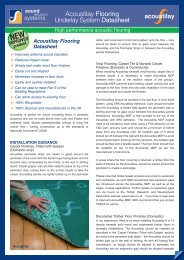
Installation Guide<br />
Acoustilay Flooring<br />
ACOUSTIC<br />
DATA 8, 9, 12, 13<br />
Acoustilay can be used above most Lath and Plaster and<br />
resiliently fixed, double plasterboarded ceilings to bring the overall<br />
floor / ceiling construction up to the standards of Approved<br />
Document E (2003)<br />
Utmost care should be taken to ensure that no gaps occur<br />
between the panels. In some situations it may be necessary to<br />
bond the Acoustilay to the sub-floor to comply with Building<br />
Regulations Approved Document E (2003).<br />
Acoustilay Installation<br />
Carpet Finishes (Fitted with gripper)<br />
Acoustilay perimeter strips are nailed or glued around the<br />
perimeter of the room with the black barrier layer facing down and<br />
the acoustic seal, compressed by two thirds, to the wall or<br />
skirting board. Carpet gripper rods are then nailed in place on top<br />
of the perimeter strip, raising them to the correct height to take<br />
the carpet. Acoustilay panels are tightly butted up to the<br />
perimeter detail, and loose laid in brick bond pattern onto the<br />
existing floorboards or Maxiboard panels.<br />
Gripper detail<br />
Acoustilay installed on a floor<br />
19
Installation Guide<br />
Vinyl & Bonded Carpet Finishes<br />
Timber Floor Finishes<br />
The Acoustilay should be bonded to the sub-floor in brick bond<br />
pattern, using the appropriate SRS adhesive. 6mm tongued and<br />
grooved Acoustilay MDF is then bonded to the top of the<br />
Acoustilay, with appropriate SRS adhesive. Alternatively, two<br />
layers of 3mm ply or MDF can be bonded onto the Acoustilay,<br />
taking care to avoid coincident joints. The MDF or plywood layer<br />
prevents point loading and joint damage in the case of vinyl and<br />
wooden floor finishes and aids installation in the case of bonded<br />
carpet and carpet tile finishes. The T&G Acoustilay MDF edge<br />
detail should be a minimum of 50mm away from any Acoustilay<br />
joint and an isolation gap of 5-10mm should be left between the<br />
wall and the MDF/Plywood to avoid sound transmission flanking<br />
into the structure, the isolation gap should be filled with a<br />
flexible sealer.<br />
Please note that timber based products are prone to expansion<br />
and contraction, as such SRS recommend that expansion gaps<br />
are introduced across the Acoustilay MDF or plywood layers, as<br />
well as at the edges, in large applications. Further details on<br />
expansion gaps can be found at the Timber Research and<br />
Development Association website: www.trada.co.uk<br />
The Acoustilay MDF boards need to be bonded to each other<br />
using a PVA adhesive on the joint. In areas where the floor<br />
covering is returned, a timber fillet, the same thickness as the<br />
Acoustilay, should be placed around the perimeter to create a<br />
solid edge.<br />
Acoustilay can be used as an underlay to timber floor finishes, to<br />
provide impact and airborne sound insulation superior to that<br />
achieved using standard underlays. The suitability of the floor<br />
finish for use with Acoustilay should be checked with the floor<br />
finish manufacturer prior to installation. The resulting floor may<br />
feel a little softer than with a standard underlay and there may be<br />
a slight movement in the finished product.<br />
If the timber floor manufacturer or installer feels that the<br />
movement is excessive, the joints should be supported by<br />
installing a layer of 6mm MDF or ply, bonded to the top of the<br />
Acoustilay, as per previous instructions in ‘Vinyl & Bonded Carpet<br />
Finishes’ section. In this case the Acoustilay should first be<br />
bonded to the floor. This treatment is also normally<br />
recommended for commercial or office applications.<br />
As with all floating floor installations, no fixings should be allowed<br />
to penetrate the resilient layer and an expansion gap should be<br />
allowed around the perimeters and services.<br />
SRS will be happy to provide samples to the floor manufacturer<br />
for test purposes. The density of the open cell resilient layer in all<br />
the Acoustilay products is 135kg/m 3 .<br />
The floor finish should then be installed on top of the Acoustilay<br />
MDF or plywood as per the manufacturer’s instructions.<br />
Commercial & Educational Applications<br />
In commercial and educational environments, such as offices and<br />
schools, it is recommended that the MDF/plywood layer is<br />
installed onto the Acoustilay to eliminate the risk of carpet rucking<br />
under wheeled furniture and to protect the carpet from heavy<br />
traffic wear.<br />
MDF detail<br />
20
Installation Guide<br />
Stairs<br />
Stair detail<br />
The Acoustilay panels should first be cut to the appropriate size.<br />
Acoustilay should then be bonded to the tread of the stair and, if<br />
airborne insulation is required, bonded to the riser using appropriate<br />
SRS adhesive. Acoustilay 3 can be formed around the nosing of the<br />
stair, as with conventional underlay.<br />
The Acoustilay 8 and 15 must be installed with Acoustilay<br />
Perimeter Strips. The perimeter strip is nailed to the tread or riser<br />
as displayed in the diagram. In areas where a nosing detail is<br />
required, a fillet of MDF, the same thickness as the Acoustilay<br />
should be installed beneath the nosing to ensure a uniform height.<br />
Fixtures and Fittings<br />
When installing Acoustilay it is important not to fix directly though<br />
the product into the sub-floor due to the risk of sound bridging.<br />
When items such as kitchen or bathroom units need to be<br />
securely fixed to the floor they should first be mounted and fixed<br />
onto an MDF plinth to the same height as the Acoustilay being<br />
used. Ideally the plinth will cover the footprint of the item and the<br />
Acoustilay can them be butted up to the MDF, maintaining a<br />
consistent floor level and providing secure fixing points. In the<br />
case of fitted cupboards and wardrobes, Acoustilay should be<br />
used to treat floors inside the cupboard to prevent flanking by<br />
airborne sound.<br />
Kitchen unit detail<br />
21
Physical Properties<br />
Cutting<br />
Fire properties:<br />
Acoustilay 3 3kg/m 2<br />
The materials used in the manufacture of Acoustilay are flame<br />
retardant. The foam is Combustion Modified and meets Schedule<br />
1 Part 1 of Statutory Instrument 1324 Amendment 1989. The<br />
surface barrier layer is self extinguishing to FMVS S302.<br />
By sharp long bladed trimming knife. Score the surface then run<br />
through with knife several times to avoid tearing. When shaping<br />
use large scissors or tin snips. A circular saw should be used for<br />
large numbers of straight cuts.<br />
Compression and dynamic loading:<br />
Acoustilay has been tested in according with BS4098:1998<br />
(1999) work of compression BS4052:1987 (1996) Dynamic<br />
Storage<br />
Must be laid flat and kept dry and protected from frost.<br />
loading test and meets the requirements of BS5808:1991 (1996)<br />
Classified luxury use, domestic/contract where high energy<br />
absorption is required.<br />
Acoustilay Accessories<br />
Perimeter strip:<br />
Thermal resistance:<br />
1200mm long x 25mm wide<br />
Acoustilay 3 Tog 2.33<br />
Acoustilay 8 strip = 6mm thick<br />
Acoustilay 8 Tog 2.35<br />
Acoustilay 15 strip = 9mm thick<br />
Acoustilay 15 Tog 2.38<br />
Tested in accordance with BS4745:1990 (ISO 5085-1:1989).<br />
Tests carried out by British Textile Technology Group, 2002.<br />
Perimeter sealer:<br />
Rolls 8m x 15mm wide and 3/15mm thick<br />
Dimensions:<br />
Sheet size = 1200 x 1200mm<br />
Thickness: Acoustilay 15 15mm<br />
Acoustilay 8 12mm<br />
Acoustilay 3 10mm<br />
Weight: Acoustilay 15 15kg/m 2<br />
Acoustilay 8 8kg/m 2<br />
22
Physical Properties<br />
Adhesive<br />
Release tackifier:<br />
10 litre tub - coverage up to 50m 2 per tub depending on substrate<br />
Acoustilay MDF:<br />
1200 x 1200 x 6mm<br />
Acrylic adhesive:<br />
5 litre tub - coverage up to 20m 2 per tub depending on substrate<br />
New, Improved Acoustilay Barrier Mat<br />
Environmental Sustainability & Human Health Credentials<br />
• UK manufactured - reduces carbon footprint<br />
• Acoustilay Barrier Mat can be manufactured from pre and post<br />
industrial waste sources. When it has completed a full service<br />
life it can be recycled again<br />
• Free from Vinyl Chloride Monomers, Lead, Bitumen, unrefined<br />
aromatic oils and allows halogen free modification<br />
• Uses more sustainable production and disposal methods than<br />
PVC<br />
• Safer disposal - Acoustilay Barrier Mat is made from a<br />
proprietary polyolefin polymer structure that is one of the least<br />
polluting plastics. It therefore poses fewer environmental risks<br />
and has a higher potential for mechanical recycling<br />
• When Acoustilay Barrier Mat burns, no hydrogen chloride gas<br />
or dioxins are formed<br />
• No PVC means that it does not require any plasticisers<br />
restricted by REACH, therefore no migration problems in landfill<br />
sites and easier disposal<br />
• Good organoleptic properties<br />
• During manufacture no toxic additives or stabilisers are used<br />
which make it easy to recycle and less harmful to the<br />
environment<br />
23
Physical Properties<br />
Fire properties:<br />
Fire propagation BS 476:Part 6: 1989 Class 0<br />
SRS Gripfix = 310ml tube<br />
Surface spread of flame:<br />
BS 476:Part 7: 1997 Class 1<br />
MAXI 60 CEILING SYSTEM<br />
Fire resistance:<br />
BS EN 1365-2: 2000<br />
Loadbearing capacity 86 min<br />
Integrity<br />
85 min<br />
Insulation<br />
85 min<br />
MAXI 30 CEILING SYSTEM<br />
Fire resistance:<br />
BS EN 1365-2: 2000<br />
Loadbearing capacity 44 min<br />
Integrity<br />
42 min<br />
Insulation<br />
42 min<br />
SRS Acoustic Sealant = 900ml tube<br />
MAXI BEAM & BLOCK SYSTEM<br />
Fire resistance:<br />
BS EN 1365-2: 2000<br />
Loadbearing capacity 132 min<br />
Integrity<br />
132 min<br />
Insulation<br />
132 min<br />
Maxiboard Dimensions:<br />
Size = 1200 x 600mm (nominal)<br />
Thickness = 17mm<br />
Weight = 24kg/m 2<br />
Maxi HP Screws = 3.9 x 30mm<br />
Maxiboard Accessories<br />
Resilient Bars = 3000mm x 120 x 30mm<br />
Cutting:<br />
Best cut using circular saw with dust extraction fitted. Can also<br />
be cut using a jigsaw or hand saw fixed with a heavy duty blade.<br />
Storage: Maxiboard must be laid flat and kept dry. Maxiboard<br />
should only be stored on site if the building has been sealed and<br />
is completely dry.<br />
24
Additional Information<br />
Finishing & Plastering Maxiboard<br />
RSJ Detail<br />
Maxi 30 Ceiling:<br />
We recommend that plasterboard be fitted over the Maxiboard<br />
and finished according to manufacturer’s instructions.<br />
Maxi 60 ceiling:<br />
12.5mm fire rated plasterboard must be fitted over the Maxiboard<br />
and finished according to manufacturer’s instructions.<br />
However, should you need to plaster directly onto the Maxiboard,<br />
we advise skimming the 10mm lighter coloured, gypsum board<br />
side of the Maxiboard. Prior to skimming, all Maxiboard joints<br />
should be filled with proprietary joint filler and taped, using paper<br />
tape, applied with undiluted plastering PVA. The whole surface<br />
should then be bonded with PVA, diluted according to the<br />
manufacturer's recommendations. A skim coat of multi-finish<br />
may then be applied. Unfortunately, SRS cannot be held<br />
responsible for the quality of any plaster finish applied directly<br />
onto Maxiboard.<br />
Where an RSJ or similar breaks the ceiling, it is essential that both<br />
the Maxiboard and the fire rated plasterboard are continued<br />
around the detail, encasing it completely. Timber noggins can be<br />
fixed into the recess of the RSJ to enable secure fixing of the<br />
boards. The cavity should be filled with mineral fibre.<br />
Downlighters<br />
Creating holes within the ceiling in order to install downlighters can<br />
have a detrimental affect on both the acoustic and fire separation<br />
properties of the ceiling, affecting both the upstairs and downstairs<br />
neighbours. However SRS provide a range of downlighters and<br />
lighting hoods that ensure both the acoustic and fire integrity of<br />
their ceiling systems. Please refer to our Acoustic Light Treatment<br />
brochure or contact the Technical Department on Tel: 01204<br />
380074 or email info@soundreduction.co.uk for further details.<br />
It is essential that the Maxiboard is free from moisture before<br />
plastering to avoid the risk of cracking at the joints. Factors such<br />
as site conditions and product storage prior to installation must<br />
be assessed before applying the skim. Should the plastering<br />
contractor suspect moisture in the Maxiboard, they should wait<br />
until the boards are fully conditioned on site.<br />
Increased acoustic performance<br />
Maxiboard – Other Applications<br />
Maxiboard is perfect for constructing small acoustic housings for<br />
noisy machinery and services, or whole room enclosures. The<br />
durability of Maxiboard combined with its capacity to take direct<br />
fixings makes it simple to use as a basic building board. To add<br />
acoustic absorption to enclosures and housings SRS Coustifoam<br />
should be applied to the internal surfaces. (See separate leaflet).<br />
Should you require an increased impact and/or airborne<br />
performance, one of the Acoustilay products can be installed on<br />
to the floor above a Maxiboard ceiling.<br />
Patents & Trademarks<br />
‘Maxiboard’ and ‘Acoustilay’ are registered trade names of<br />
Sound Reduction Systems Ltd. Both are patented products.<br />
Maxiboard Patent No: GB2375358<br />
Acoustilay Patent No: GB2287086<br />
25
Additional Information<br />
Important Notes<br />
Approved Document E 2003 introduces a new unit of<br />
measurement for airborne sound, which places much more<br />
emphasis on low frequency performance. Due to the inherent<br />
difficulties of measuring low frequency noise, a significant<br />
tolerance on the accuracy of airborne sound test results<br />
should be expected. In practical test PASM have witnessed<br />
relatively large variations in airborne sound results by different<br />
measurement contractors on the same floor. Site conditions<br />
and workmanship can also limit reproducible results; therefore<br />
previous results should be viewed as indicative of<br />
performance only.<br />
Site conditions and installation standards vary. SRS cannot<br />
take responsibility for the performance of any installed system<br />
of which the Maxiboard or Acoustilay is only a part, or that has<br />
been installed incorrectly. Prior to installation it is necessary to<br />
identify and eliminate possible flanking paths that may<br />
compromise the acoustic performance of any SRS system.<br />
Acoustic Testing<br />
The final performance of a separating structure is assessed during<br />
a Sound Insulation (SI) test. In the case of both walls and floors,<br />
this is done by determining the level difference achieved when<br />
measuring a loud noise source through the structure, in<br />
accordance with BS EN ISO 140-4 ‘Measurement Procedure for<br />
Airborne Noise transmission’. The result is given as a single figure<br />
known as the Standardised Level Difference, or D nT,w , in decibels<br />
dB. A higher figure indicates better performance. A similar<br />
measurement made in a laboratory under ideal conditions gives<br />
the Sound Reduction Index (SRI) which is abbreviated to R w .<br />
Typically, an R w is around 5dB higher than the equivalent D nT,w<br />
figure. In Building Regulations Part E – Resistance to the Passage<br />
of Sound, relating to residential buildings, there is an additional<br />
frequency weighting, C tr which gives greater significance to<br />
performance at low frequencies.<br />
Separating floors have an additional test to assess the level of<br />
impact noise insulation. This is made using a calibrated tapping<br />
machine which delivers regular and repeatable impacts. The level<br />
in the receiver room is measured, giving a L nT,w (dB) figure.<br />
Similarly, the level measured in a laboratory is given as L nw dB. A<br />
lower figure indicates better performance.<br />
When Part E was introduced in 2003, a requirement for precompletion<br />
testing was added. The regulations now require 10%<br />
of each type of construction to be tested in order to show that<br />
they meet or exceed the Part E standards. The only alternative for<br />
new build projects is to use Robust Details. These are a range of<br />
constructions which have been demonstrated to exceed Part E<br />
standards by at least 5dB.<br />
26
Ultimate Acoustic Solutions for<br />
Walls & Partitions<br />
Uniclass<br />
L384+L516:N372<br />
EPIC<br />
C441+E23:Y45<br />
CI/SfB<br />
(22.3)+(42) R (P2)<br />
For more acoustic<br />
solutions, please refer<br />
to our “Walls &<br />
Partitions” brochure<br />
Contains SRS Ltd’s Rigorous<br />
Standard Details for:<br />
Building Regulations<br />
Approved Document E<br />
BB93 – Schools<br />
HTM 2045/HTM 56 –<br />
Hospitals
Sound Reduction Systems Ltd<br />
Adam St, Off Lever St, Bolton BL3 2AP<br />
Tel: +44 (0)1204 380074 · Fax: +44 (0)1204 380957<br />
E-mail: info@soundreduction.co.uk · Web: www.soundreduction.co.uk<br />
Site conditions and installation standards vary. SRS cannot take responsibility for the performance of any installed system of which SRS products are only a part, or that have been<br />
installed incorrectly. Prior to installation, it is necessary to identify and eliminate possible flanking paths that may compromise the acoustic performance of any SRS product.