FuelMaster®
Titan FuelMaster Operation Manual :: Commercial Fuel Solutions Ltd
Titan FuelMaster Operation Manual :: Commercial Fuel Solutions Ltd

You also want an ePaper? Increase the reach of your titles
YUMPU automatically turns print PDFs into web optimized ePapers that Google loves.
OPERATION<br />
MANUAL<br />
Storage tanks with integral dispenser,<br />
volume 1200, 2500, 3500, 5000, 9000 & 10000 litres<br />
<strong>FuelMaster®</strong><br />
EN
OPERATION MANUAL<br />
PORTABLE<br />
FUEL OIL BATCHING MACHINES<br />
VOLUME 1200, 2500, 3500, 5000, 9000 & 10000 L<br />
FuelMaster ®<br />
by TITAN ENVIRONMENTAL<br />
(rev. 4/2008)
CONTENTS<br />
I. PURPOSE ............................................................................................................................................ 3<br />
II. TECHNICAL PARAMETERS AND EQUIPMENT ............................................................................... 3<br />
1. DIMENSIONS .................................................................................................................................. 3<br />
2. EQUIPMENT ................................................................................................................................... 4<br />
3. PUMP .............................................................................................................................................. 7<br />
4. MECHANIC FLOWMETER. ............................................................................................................ 8<br />
5. DIGITAL FLOWMETER ................................................................................................................ 10<br />
A. GENERAL ................................................................................................................................. 10<br />
B. OPERATING PRINCIPLE. ........................................................................................................ 13<br />
C. CALIBRATION .......................................................................................................................... 15<br />
D. MACHINE CONFIGURATION ................................................................................................... 19<br />
E. MAINTENANCE ........................................................................................................................ 20<br />
6. LEVEL INDICATOR – OIL WATCHMAN PLUS ............................................................................ 22<br />
A. DESCRIPTION .......................................................................................................................... 22<br />
B. ACTIVATION OF WATCHMAN PLUS ...................................................................................... 23<br />
7. TANK OVERFILL PROTECTION .................................................................................................. 25<br />
8. MACHINE’S LITRE CAPACITY CHART ....................................................................................... 26<br />
III. TRANSPORT AND STORAGE .......................................................................................................... 27<br />
IV. GENERAL SETUP REQUIREMENTS ............................................................................................... 28<br />
V. ELECTRICAL SYSTEM ..................................................................................................................... 30<br />
1. EARTHING .................................................................................................................................... 30<br />
2. TEMPORARY POWER SUPPLY .................................................................................................. 30<br />
3. PERMANENT POWER SUPPLY .................................................................................................. 31<br />
VI. GENERAL SAFETY PRINCIPLES .................................................................................................... 33<br />
VII. OPERATIONAL RECOMMENDATIONS ........................................................................................... 34<br />
1. REFUELLING OF MACHINES ...................................................................................................... 34<br />
2. REFUELLING OF VEHICLE ......................................................................................................... 35<br />
VIII. MACHINE MAINTENANCE ............................................................................................................... 36<br />
IX. TROUBLESHOOTING ....................................................................................................................... 37<br />
X. GUARANTEE TERMS ....................................................................................................................... 38
FuelMaster ®<br />
I. PURPOSE<br />
FuelMaster ® is a bunded fuel storage tank with transfer equipment double-jacket, overground tank with<br />
volume 1,200, 2,500, 3,500, 5,000 or 9,000l, equipped with fuel batching device.<br />
Only fuel oil can be stored in FuelMaster ® tanks. Storage of petrol and other fluids is<br />
prohibited.<br />
II.<br />
TECHNICAL PARAMETERS AND EQUIPMENT<br />
1. DIMENSIONS<br />
Symbol BFM01200DG/* BFM02500DG/* BFM03500DG/* BFM05000DG/* BFM09000DG/*<br />
Rated volume<br />
[litres]<br />
1200 2500 3500 5000 9000<br />
Length [m] 1,90 2,46 2,85 2,84 3,25<br />
Width [m] 1,24 1,46 2,20 2,23 2,45<br />
Height [m] 1,77 1,85 1,96 2,34 2,95<br />
Weight [kg] 150 220 280 320 490<br />
Dimensions can vary by +/- 1%.<br />
* - Two last characters of the code indicate equipment options: AF – analogue meter, DF – digital<br />
meter, MU - multi-access distributor (only 3,500 , 5,000 and 9000 l), ZP – legalized distributor<br />
(only 5,000 and 9,000 l).<br />
Rated volume is 95% of overflow volume.<br />
Double-jacket tank (tank within a tank), with internal tank volume of 1,200 l, 2,500 l, 3,500 l, 5,000 l<br />
i 9,000 l is executed in UV stabilised medium density polyethylene.<br />
3
2. EQUIPMENT<br />
Mechanic<br />
flowmeter zeroing<br />
handwheel<br />
Level sensor signal<br />
transmitter<br />
Maximum level<br />
sensor terminal<br />
Pump suction line<br />
Pump-mechanic<br />
flowmeter unit<br />
Refuelling line<br />
connection<br />
Pump venting<br />
line<br />
Earthing line<br />
Distribution<br />
hose<br />
Pump filter lid<br />
Pump electric box<br />
Filler nozzle<br />
(open distributor enclosure of machines<br />
with volume 3,500 l and above)<br />
Level sensor<br />
probe connection<br />
Maximum level<br />
sensor probe<br />
Suction line 1”<br />
Pump venting hose<br />
(tank inlet)<br />
Inspection hole of<br />
internal tank 4”<br />
(open inspection lid of machines<br />
with volume 3,500 l and above)<br />
Filler line 2” with<br />
mechanic overflow<br />
protection<br />
4
Automatic<br />
Filler nozzle<br />
Level sensor<br />
Maximum level<br />
sensor probe<br />
Digital<br />
flowmeter<br />
Pump<br />
230 V AC.<br />
Pump filter<br />
lid<br />
Pump venting<br />
hose<br />
Inlet 2”<br />
(open distributor enclosure of machines<br />
with volume 1,200 l and 2,500 l with digital flowmeter)<br />
Inspection<br />
lid 4”.<br />
1. Fuel distributor unit is equipped with:<br />
−<br />
−<br />
−<br />
−<br />
suction hose 1” with non-return valve and mesh filter on end;<br />
flowmeter indicating quantity (litres) of pumped oil from last zeroing, and total flow; there are<br />
two flowmeter variants available – mechanic and digital.<br />
a pump, supply 230V, max. output 56 l/min (1,200 and 2,500 l) or max. 72 l/min (3,500 and<br />
5,000 l);<br />
filler nozzle with stop valve automatically cutting off fuel flow upon reaching maximum level<br />
in refuelled tank;<br />
− distribution hose dia. ¾” and length 4 m (1,200 and 2,500 l) or 6 m (3,500, 5,000<br />
and 9,000 l).<br />
2. Current oil level sensor – Watchman Plus, with integrated jacket-to-jacket leak sensor.<br />
Machine comprises:<br />
− level probe installed inside of tank;<br />
− leak sensor (signals leaks in internal tank);<br />
− transmitter mated with probe and sensor;<br />
− receiver with single-digit display (plug with antenna).<br />
5
3. Maximum level sensor.<br />
Appliance comprises a probe installed on top of internal tank, and a plug to be connected to<br />
circuit signalling exceeding of maximum level, or automatically switching off unloading pump on<br />
mobile cistern. Appliance protects the tank of portable distributor from overfill and overflow<br />
during unloading.<br />
4. Vent in internal tank.<br />
The vent is installed inside internal tank (invisible from the outside), and it compensates pressure<br />
level in the tank during refuelling and unloading.<br />
5. Inspection lid dia. 4” in internal tank.<br />
6. Two inspection lids 16” in tanks with volume over 3,500 l.<br />
One with a closure, in external tank, and one, invisible from the outside, in internal tank (access<br />
after disassembly of external tank).<br />
7. Inlet in the form of two inch ferrule in distributor enclosure, allowing tight connection with mobile<br />
cistern. Machines with volume above 3,500 l are equipped with refueling line, comprising<br />
connection in distributor enclosure, hose and mechanic overfill protection – Spill Stop.<br />
8. Distributor enclosure is locked with two locks, with keys.<br />
9. Earthing going outside of distributor enclosure.<br />
*Equipment can vary depending on tank variant.<br />
6
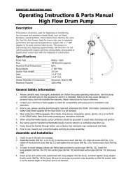
3. PUMP<br />
Pump filter lid<br />
Pump unit comprises:<br />
PUMP: Self-priming pump, electric sliding-vane pump, with by-pass valve.<br />
MOTOR: Asynchronous, single-phase, 2 pole, totally-enclosed type motor (protection index IP<br />
55, as per EN 60034-86), with integrated ventilation, connected via flange directly to<br />
body.<br />
FILTER: Suction side filter, suitable for periodic inspection.<br />
SPECIFICATIONS OF TECHNICAL PARAMETERS<br />
1. Maximum flow rate:<br />
− for machines with volume 1,200 and 2,500 – 56 l/min.<br />
− for machines with volume 3,500 , 5,500 and 9,000 – 72 l/min.<br />
2. Allowed working temperature: min -20 o C / max +60 o C.<br />
3. Allowed viscosity of fuel oil from 2 to 5.35 cSt.<br />
4. Allowed relative humidity max 90%.<br />
5. Power supply voltage 230V AC ± 5% of rated value.<br />
6. Power supply frequency 50 Hz ± 2% of rated value.<br />
7. Power consumption 370 W (1200, 2500 l) and 500 W (3500, 5000, 9000 l).<br />
8. Allowed by-pass working time (with inlet blocked): 2 – 3 minutes.<br />
9. Lifting height max 2m.<br />
10. Motor pump protection – automatic thermal circuit-breaker.<br />
11. Protection index IP55.<br />
Details of pump design and operation are included in operation manual by pump manufacturer.<br />
7
4. MECHANIC FLOWMETER.<br />
Mechanic flowmeter is activated by flowing liquid, propelling gear installed in meter body lid.<br />
The meter is equipped with non-adjustable.<br />
TECHNICAL DATA<br />
Meter mechanism<br />
Flow rate (range)<br />
Working flow (max.)<br />
Bursting pressure (min.)<br />
Storage temperature (range)<br />
Nutanting disc<br />
20 - 120 litres/min.<br />
3.5 bar<br />
28 bar<br />
- 20 o C + 80 o C<br />
Storage humidity (max.) 95%<br />
Working temperature (range)<br />
Pressure losses (flow rate in l/min.)<br />
With fuel oil (Diesel)<br />
-10 o C + 60 o C<br />
30 - 60<br />
Pressure loss (bar) 0.05 - 0.2<br />
Accuracy following calibration +/-1%<br />
Repeatability (typical) +/- 0.3%<br />
Reading precision<br />
Connection (inlet/outlet)<br />
0.1 litre<br />
1” (one inch) BSP<br />
Calibration<br />
Flowmeter is pre-calibrated at the plant for application with fuel oil. Since specific working conditions<br />
(such as flow rate, properties and temperature of measured fluid) can affect accuracy of measuring<br />
device, recalibration is to be carried out periodically.<br />
Current meter -<br />
zeroed.<br />
Meter zeroing<br />
handwheel.<br />
Total meter -<br />
non-zeroed.<br />
Brass screw - plug.<br />
When unscrewed it<br />
gives access to<br />
adjustment screw.<br />
8
1. Unscrew the plug – brass screw.<br />
2. Vent air out of the system by batching until solid, continuous flow.<br />
3. Cut off the flow by switching off filler nozzle; leave the pump working.<br />
4. Zero current meter using handwheel.<br />
5. Batch at flow rate that requires the highest accuracy, using calibration tank, volume not less than<br />
20 litres. Do not reduce flow to reach the scaled area of calibration tank. Recommended method<br />
is switching full flow on and off, for a couple of times, until required refill is reached.<br />
6. Compare value indicated on calibration tank (actual value) with meter indication (indicated<br />
value).<br />
−<br />
when indicated value is higher than actual value, loosen the screw; counter-clockwise.<br />
− when indicated value is lower than actual value, tight the screw; clockwise.<br />
7. Repeat operations in 4 – 6 until required accuracy is achieved.<br />
8. Re-tighten the plug.<br />
The purpose of self-sealinging o-ring set on calibration screw, is to prevent accidental loosening of<br />
adjustment screw – the ring performs no sealinging function whatsoever. Thus it is required to<br />
properly screw the plug with sealing every time.<br />
9
5. DIGITAL FLOWMETER<br />
A. GENERAL<br />
Measurement is based on oval gears, which ensure high accuracy in the broad range of flow rates,<br />
and low pressure loss. Fluid flowing through machine propels gears, which rotate and transport<br />
“units” of fluid. Precise measurement of batched fluid is carried out by counting rotations of gears<br />
(“units” passing gears). After each full rotation cycle magnets installed in gears send signals to<br />
magnetic sensor located in measurement chamber. Signals are received and processed by<br />
microchip.<br />
Inlet is equipped with mesh filter in stainless steel, accessible after removing of flange installed on<br />
inlet side.<br />
User can select one of two operating modes:<br />
− Normal mode: Partial or total quantity of batched fluid is displayed.<br />
− Flow rate mode: Flow rate and partial quantity of batched fluid are displayed<br />
Meter is equipped with non-volatile memory and stores quantitative flow data, also in the event of<br />
long power failures.<br />
LCD<br />
display<br />
CAL button<br />
Battery<br />
chamber<br />
Filter<br />
Measurement<br />
10
Main components:<br />
Measuring electronics and LCD are installed on top of flowmeter, and they are isolated from<br />
fluid-filled measuring chamber and protected from effects of the environment by means of enclosure.<br />
Flowmeter technical parameters.<br />
Values for fuel oil<br />
Meter<br />
Resolution l/impulse 33.5<br />
Flow rate range l/min. 100 –100<br />
Working pressure bar 30<br />
Bursting pressure bar 60<br />
Measuring system<br />
Oval gears<br />
Storage temperature °C -20 – +70<br />
Storage humidity H.R. 95%<br />
Maximum working temperature °C - 10 – +60<br />
Pressure loss at maximum flow rate bar 0,3(Fuel oil in 20°C)<br />
Measured fluids<br />
Fuel oil<br />
Viscosity range cSt 2 – 5,35<br />
Accuracy (regarding measured volume) ±0,5<br />
Repeatability 0,2%<br />
Threaded inlet and outlet connection point 1”<br />
Batteries<br />
2 x 1,5 V<br />
Battery life (estimated)<br />
18-36 months<br />
11
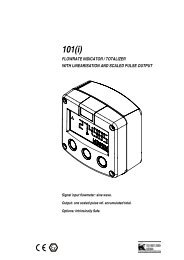
LCD screen<br />
Meter screen comprises two numeric records and various indicators displayed when given<br />
functionality requires so.<br />
Explanation:<br />
1. Subtotal register (partial register, 5 digits with moving colon: 0,000 ÷ 99999 ) indicating quantity<br />
of fluid transferred since the last time RESET button was pressed.<br />
2. Battery charging level indicator.<br />
3. Calibration mode indicator.<br />
4. Total and Reset Total register (6 digits with moving colon 0,0÷999999 x10 / x100).<br />
4.1. Total, not zeroable (TOTAL).<br />
4.2. Reset total (RESET TOTAL).<br />
5. Total multiplier indicator ((x10 / x100).<br />
6. Total type indicator (TOTAL / RESET TOTAL).<br />
7. Total measurement unit indicator: L = litres, Gal=gallons.<br />
8. Flow rate indicator.<br />
9. Subtotal measurement unit indicator: Qts=quarts, Pts=pints, L=litres, Gal=gallons.<br />
User buttons<br />
Meter is fitted with two buttons (RESET and CAL). Each of them has a primary functionality<br />
assigned. When pressed together they have a secondary functionality assigned.<br />
Primary functions:<br />
−<br />
RESET button: zeroes subtotal and reset total register,<br />
− CAL button: sets the device in calibration mode.<br />
Pressing of both buttons together sets the device sin configuration mode, where desired<br />
measurement unit can be set.<br />
Battery chamber<br />
The device is powered by two standard 1,5V batteries (size N).<br />
Battery chamber is sealinged with threaded water-proof plug, which can be easily removed for quick<br />
battery replacement.<br />
12
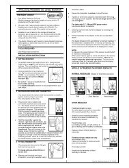
B. OPERATING PRINCIPLE.<br />
Due to adoption of suitable calibration ratio (i.e. “weight” of a single impulse), integrated microchip<br />
(in executions with meter) or external microchip (in executions with pulse generator), translates<br />
impulses caused by fluid into measurement units displayed in subtotal and total register.<br />
Flowmeters have factory coefficient K set to obtain optimum measurement conditions for fuel oil.<br />
Calibration settings can be changed in a way as described in this manual; restoring of factory<br />
settings is possible at any time.<br />
Illustrations below show two typical display indications. First of them shows subtotal register and<br />
reset total register. The second shows subtotal and total.<br />
Switching between reset total to total indication is automatic and depends on time intervals as set in<br />
factory, which cannot be changed by user.<br />
SUBTOTAL REGISTER<br />
RESET<br />
TOTAL<br />
REGISTER<br />
TOTAL<br />
REGISTER<br />
−<br />
Subtotal register in the upper part of display indicates quantity of batched fluid since the last<br />
time RESET button was pressed.<br />
− Reset total register in the lower part of display indicates quantity of batched fluid since the<br />
last time reset total was zeroed. Reset total cannot be zeroed before subtotal is zeroed, and<br />
subtotal can be zeroed at any time without zeroing of reset total. Measurement unit of both<br />
totals can be identical as of subtotal or different, as per factory or user setting.<br />
User cannot zero total register (TOTAL). Total reading increases throughout the whole flowmeter<br />
lifecycle.<br />
Since reset total and total are displayed in the same area of LCD screen, they can only be seen<br />
alternately.<br />
The device is programmed to display those values in regular time intervals.<br />
TOTAL IS DISPLAYED WHEN DEVICE IS IN STAND-BY MODE.<br />
RESET TOTAL IS DISPLAYED:<br />
−<br />
−<br />
−<br />
some time following zeroing of subtotal (a few seconds),<br />
always during batching,<br />
some time following batching completion. In no time the device switches to stand-by mode<br />
and lower register indicates total.<br />
NOTE:<br />
Totals are displayed using maximum of 6 digits and two symbols x10 / x100. Display<br />
switches to higher multiplier in the following sequence: 100000 x 10 ›? 999999 x 10 ›?<br />
100000 x 100 ›? 999999 x 100.<br />
Batching in emergency mode<br />
It is a standard batching mode, when subtotal and reset total are displayed<br />
simultaneously during counting of units.<br />
Accidental pressing of RESET or CAL button during counting of units should have<br />
no effect to meter reading.<br />
13
Within a few seconds following batching, reset total in lower register shall be<br />
replaced with reset total. RESET symbol above TOTAL symbol shall disappear,<br />
and reset total value shall be replaced with total value.<br />
This is so-called standby mode (STANDBY) which lasts until device reactivation.<br />
Zeroing subtotal.<br />
Subtotal is zeroed using RESET button in standby mode, i.e. when display<br />
indicates TOTAL symbol.<br />
After RESET button is pressed the value is zeroed; display indicates all<br />
highlighted digits, and then all not highlighted digits.<br />
When zeroing is complete display shows zeroed subtotal and reset total.<br />
A moment later reset total is replaced with non-reset TOTAL.<br />
Zeroing reset total.<br />
Reset total can be zeroed only after subtotal is zeroed. Reset total can be zeroed<br />
by pressing RESET button when display shows RESET TOTAL symbol, as<br />
illustrated below.<br />
Follow the sequence below:<br />
1. Wait until the device switches into standby mode (display shall indicate only<br />
TOTAL symbol).<br />
2. Press RESET button shortly.<br />
3. The device shall start zeroing of subtotal.<br />
4. When display indicates RESET TOTAL press and hold RESET button for at<br />
least 1 second.<br />
5. Display shall indicate as per following sequence: all fields, off fields, and RESET<br />
TOTAL screen.<br />
Batching in flow rate measuring mode.<br />
It is possible to batch and simultaneously display:<br />
− currently batched quantity,<br />
− flow rate [subtotal unit / minute], as on display on the right.<br />
To switch to this mode:<br />
− wait until the devices switches to standy mode, i.e. when display indicates<br />
only TOTAL,<br />
− press CAL button shortly,<br />
− start batching.<br />
Flow rate is updated every 0.7 second. Thus at low flow rates display indications<br />
can be unstable. The highest flow rate the more stable display readings.<br />
NOTE: Flow rate is expressed in measurement units as selected for subtotal; when<br />
measurement units of subtotal and total differ, as in the example below, bear in mind that<br />
flow rate is expressed in subtotal units. In the example below flow rate is expressed in Qts<br />
(quarts) per minute.<br />
14
“Gal” symbol displayed next to flow rate refers to total or reset total register, which shall be<br />
displayed after leaving flow rate measurement mode.<br />
Press CAL button again to return to normal mode. Accidental pressing of RESET or CAL button<br />
during counting of units should have no effect to meter reading.<br />
Note: Both reset total and total increase during batching in this mode, although they are not<br />
displayed. Their values can be checked after completion of batching and returning to normal<br />
mode by pressing CAL button shortly.<br />
Zeroing subtotal.<br />
To zero subtotal after completion of batching wait until meter indicates flow rate<br />
equal to 0.0, as in the drawing on the right:<br />
and then press RESET button shortly.<br />
Contrary to normal mode in this case during zeroing the device does not follow the<br />
sequence of alternate highlighting and dimming of display fields – subtotal is<br />
zeroed immediately.<br />
C. CALIBRATION<br />
Calibration, or “K”, coefficient is a multiplier used by system to calculate received electric impulses to<br />
fluid measurement units.<br />
Factory K coefficient: K coefficient with value set in the factory. Its value is 1.000 . Such coefficient<br />
ensures maximum accuracy in following conditions:<br />
− Engine oil type SAE10W40<br />
− Temperature: 20°C<br />
− Flow rate: 6-60 l/min<br />
Factory K coefficient can be easily restored, regardless of changes introduced by user.<br />
User defined K coefficient: Specially selected calibration coefficient, i.e. set by way of calibration.<br />
Calibration procedure.<br />
Flowmeter allows fast and precise electronic calibration by modification of calibration coefficient (K).<br />
Calibration coefficient can be modified as follows:<br />
a) calibration through batching,<br />
b) direct calibration, by means of changing calibration coefficient.<br />
Enter calibration mode (press and hold CAL button), and:<br />
− display presently used calibration coefficient,<br />
− restore calibration coefficient to factory value to reverse modification by user,<br />
− modify calibration coefficient using one of the procedures above.<br />
Quantities of batched fluid – subtotal and total – displayed in calibration mode differ in meaning at<br />
different stages of calibration procedure.<br />
In calibration mode you cannot use meter for normal batching of fluid.<br />
In calibration mode total/subtotal is not increasing.<br />
15
NOTE<br />
Device includes a non-volatile memory where calibration data and total<br />
batched quantity is stored. There is no need to repeat calibration even after<br />
long power outing or after battery replacement.<br />
Displaying current calibration coefficient, restoring factory value.<br />
Current calibration coefficient is displayed after pressing CAL button in standby<br />
mode.<br />
There are two possibilities:<br />
a) When no calibration was carried out so far, or after previous calibrations<br />
factory value was restored, display shall indicate FACT (for Factory); it<br />
means that factory calibration coefficient is set.<br />
b) Had the user carried out calibration, currently used calibration coefficient is displayed (in this<br />
case it is 0.998).<br />
Symbol “User” indicates that calibration coefficient used was defined by user.<br />
Attached block diagram shows the sequence with<br />
respective display indications.<br />
In calibration mode RESET button allows switching<br />
from user’s coefficient to factory coefficient.<br />
To confirm selection of calibration coefficient when<br />
USER or FACT symbols are displayed, press CAL<br />
button shortly.<br />
After returning to normal mode the device shall use<br />
confirmed calibration coefficient.<br />
IMPORTANT:<br />
Upon confirmation of factory calibration<br />
coefficient old user value is deleted from memory.<br />
Calibration by batching<br />
Procedure requires batching of fluid to standard measurement tank in actual working conditions (flow<br />
rate, viscosity, etc.), requiring maximum accuracy.<br />
CAUTION!<br />
Successful completion of calibration procedure requires that:<br />
−<br />
−<br />
−<br />
−<br />
−<br />
prior to embarking calibration air is to be completely removed from the system;<br />
carefully selected standard measurement tank is used, volume not less than 5 litres, fitted<br />
with precision scale indicator;<br />
batching is carried out at constant flow rate typical for standard operation, until the tank is<br />
full;<br />
flow rate is not reduced at the final stage of refuelling to achieve „to mark” refuelling of tank;<br />
correct method of ending the refuelling is to batch small amounts, keeping normal flow rate);<br />
upon completion of refuelling wait a few minutes to make sure that no air bubbles are<br />
prezent in standard tank; read the value after fluid level settles.<br />
16
Follow the procedure below.<br />
Calibration by batching:<br />
ACTION<br />
DISPLAY SCREEN<br />
1<br />
NO ACTION<br />
Device in normal mode (not counting).<br />
PRESSING AND HOLDING CAL BUTTON<br />
2<br />
3<br />
Devices enters calibration mode, CAL symbol is displayed and calibration<br />
coefficient indication replaces subtotal indication. Symbols FACT and USER<br />
indicate which coefficient (user’s or factory) is presently selected.<br />
PRESSING AND HOLDING RESET BUTTON<br />
CAL symbol is displayed and subtotal zeroed. The device is ready for<br />
calibration by batching.<br />
BATCHING TO STANDARD TANK<br />
Do not press any button, start refuelling the standard tank.<br />
4<br />
You can stop and restore refuelling the tank at any time. Fluid level in tank is<br />
to reach the marked area. There is no need to fill the tank with any specific<br />
quantity of fluid.<br />
Indicated value<br />
Actual value<br />
PRESSING RESET BUTTON<br />
5<br />
6<br />
Device is notified on completion of batching procedure.<br />
Prior to performing this action make sure that batching is completed<br />
successfully. To calibrate the device replace the value indicated in subtotal<br />
register (e.g. 9,800) with actual value taken from the scale of standard tank.<br />
In bottom left corner of display an arrow appears (up or down arrow) pointing<br />
direction (increase or decrease) in the change of user K value during action<br />
6 and 7.<br />
PRESSING RESET BUTTON<br />
Changes arrow direction. This action can be repeated a number of times.<br />
PRESSING/PRESSING AND HOLDING CAL BUTTON<br />
7<br />
Indicated value changes in direction indicated by arrow, one unit per each<br />
pressing of CAL button, or continuously when CAL button is pressed and held<br />
(slowly for first 5 seconds and then fast).<br />
When desired value is exceeded repeat procedure, starting from point (6).<br />
17
PRESSING AND HOLDING RESET BUTTON<br />
Device is notified on completion of batching procedure. Prior to performing<br />
this action make sure that INDICATED value equals ACTUAL value.<br />
8<br />
Indicated value<br />
Actual value<br />
NO ACTION<br />
9<br />
10<br />
Upon completion of calculations a new user K coefficient is displayed for a few<br />
seconds, and then the activation cycle continues until the devices switches to<br />
standby mode.<br />
IMPORTANT: From this moment on the device shall use indicated<br />
calibration coefficient, even after battery replacement.<br />
NO ACTION<br />
The device keeps the new calibration coefficient and is ready for batching<br />
fluid using newly defined K coefficient.<br />
Direct modification of K coefficient<br />
Below described procedure is particularly useful when correcting “average error” determined based<br />
on a few batchings.<br />
When meter indicates specific average per cent value of error it can be modified by correcting<br />
currently used calibration coefficient by this per cent value. In this case correction of user K<br />
coefficient can be calculated as follows:<br />
New calibration coefficient = old calibration coefficient x (100 - E%) / 100.<br />
Example:<br />
Value of observed error E%. : - 0.9 %<br />
PRESENT calibration coefficient : 1,000<br />
New coefficient : 1,000 * [(100 - (-0,9))/100] = 1,000 * [(100+0,9)/100] = 1,009<br />
User calibration<br />
When the device underrates the quantity of batched fluid (negative error), new calibration coefficient<br />
is to be higher than the old one, as in example below: When the device overrates the quantity of<br />
batched fluid (positive error) new calibration coefficient is to be lower than the old one.<br />
ACTION<br />
DISPLAY SCREEN<br />
1<br />
NO ACTION<br />
Device in normal mode (not counting).<br />
PRESSING AND HOLDING CAL BUTTON<br />
2<br />
Devices enters calibration mode, CAL symbol is displayed and calibration<br />
coefficient indication replaces subtotal indication. Symbols FACT and USER<br />
indicate which coefficient (user’s or factory) is presently selected.<br />
PRESSING AND HOLDING RESET BUTTON<br />
3<br />
CAL symbol is displayed and subtotal zeroed.<br />
The device is ready for calibration by batching – see previous section.<br />
18
PRESSING AND HOLDING RESET BUTTON<br />
4<br />
You can start direct modification of calibration coefficient. DIRECT symbol is<br />
displayed, along with presently used calibration coefficient.<br />
In bottom left corner of display an arrow appears (up or down arrow) pointing<br />
direction (increase or decrease) in the change of displayed value during action<br />
5 and 6.<br />
PRESSING RESET BUTTON<br />
5<br />
Changes arrow direction. This action can be repeated a number of times.<br />
6<br />
PRESSING/PRESSING AND HOLDING CAL BUTTON<br />
Displayed value changes in direction indicated by arrow, one unit per each<br />
pressing of CAL button, or continuously when CAL button is pressed and held<br />
(the faster the longer the button is held).<br />
When desired value is exceeded repeat procedure, starting from point (5).<br />
7<br />
PRESSING AND HOLDING RESET BUTTON<br />
The device is notified on completion of calibration procedure. Prior to<br />
performing this action make sure that indicated value equals actual value.<br />
NO ACTION<br />
8<br />
9<br />
After completion of calculation a new user K coefficient is displayed for a few<br />
seconds, and then activation cycle is repeated until the devices switches to<br />
standby mode.<br />
IMPORTANT: From this moment on the device shall use indicated<br />
calibration coefficient, even after battery replacement.<br />
NO ACTION<br />
The device keeps the new calibration coefficient and is ready for batching fluid<br />
using newly defined K coefficient.<br />
D. MACHINE CONFIGURATION<br />
User can select the following measurement unit from flowmeter counter’s menu: Quarts (Qts), pints<br />
(Pts), litres (Lit) or gallon (Gal). Relation between subtotal and total register unit is described in table<br />
below.<br />
Combination No. Subtotal register unit Total and reset total unit<br />
1 Litres (Lit) Litres (Lit)<br />
2 Gallons (Gal) Gallons (Gal)<br />
3 Quarts (Qts) Gallons (Gal)<br />
4 Pints (Pts) Gallons (Gal)<br />
To select from 4 available combinations:<br />
−<br />
−<br />
Wait until meter switches to standby mode.<br />
Press and hold CAL and RESET buttons until UNIT symbol is displayed,<br />
along with currently selected measurement unit (in this example<br />
litres / litres).<br />
Each pressing of RESET button causes displaying subsequent combination of units, as in drawing<br />
below.<br />
19
Holding of CAL button causes saving of newly selected setting; meter performs activation cycle and<br />
is ready for batching in selected units.<br />
NOTE<br />
Values in reset total and total registers are displayed with new measurement unit.<br />
The device does NOT require calibration after changing of measurement unit.<br />
E. MAINTENANCE<br />
The machine is designed and manufactured in a way requiring minimum maintenance.<br />
The only maintenance operations required are:<br />
−<br />
−<br />
Changing batteries when they expire.<br />
Cleaning measurement chamber. Cleaning might be required due to properties of batched fluids<br />
or the presence of fine solids due to bad filtering.<br />
Changing batteries<br />
The meter is delivered with two standard 1,5V alkali batteries (size N).<br />
Meter can display two types of low battery warnings:<br />
1) When battery charging level displayed In LCD drops below level 1, battery<br />
symbol appears.<br />
Meter operates normally, battery symbol reminds operator to change batteries.<br />
2) If the meter is operated without changing batteries, the second warning shall<br />
appear and meter function is blocked. Battery symbol starts to pulse and it is<br />
the only symbol displayed.<br />
NOTE<br />
Expired batteries are to be disposed of in accordance with regulations in force.<br />
To change batteries follow the sequence below (items as per diagram on page 11):<br />
− Press RESET button to update the totals.<br />
− Unscrew battery compartment cover (item 4).<br />
− Remove used batteries.<br />
− Insert new batteries into battery compartment, mind orientation (see instructions on<br />
compartment cover - item 3). Screw in battery compartment cover; make sure sealinging<br />
(item 4) is placed correctly.<br />
20
The meter switches on automatically and it is ready for operation.<br />
The values of reset total, total and subtotal displayed by meter should be the same as before.<br />
Following changing of batteries, and after power failure, the meter reactivates and uses the same<br />
calibration coefficient that was used before power failure. Thus no recalibration is required.<br />
Cleaning measurement chamber.<br />
Flowmeter measurement chamber can be cleaned without disconnecting the machine from pipeline.<br />
Prior to closing the lid make sure that gears rotate freely.<br />
CAUTION!<br />
Prior to cleaning make sure that no liquid is present in the machine.<br />
To change batteries follow the sequence below (items as per diagram on page 11):<br />
− Loosen four bolts of bottom lid (item 7).<br />
− Remove the lid (item 7) and sealing (item 6).<br />
−<br />
Remove oval gears.<br />
− Clean the chamber, if necessary. Use a brush or pointed object, such as screwdriver. Avoid<br />
damaging enclosure or gears.<br />
−<br />
Reassemble the machine following above sequence In reverse.<br />
CAUTION<br />
Replace gears as per diagram included.<br />
CAUTION<br />
Magnets are included with only one of two coupled gears, as in the<br />
drawing. Mind orientation of gears with magnets, see included drawing.<br />
Replace second gear (one without magnets), with axis at angle not<br />
exceeding 90° as related to first gear.<br />
Cleaning filter<br />
Filter is to be cleaned in intervals depending on content of impurities in fluid. To clean filter<br />
disconnect the machine from pipeline, since filter is installed between enclosure and connection<br />
flange.<br />
CAUTION!<br />
Prior to cleaning make sure that no fluid is present in the machine.<br />
Filter cleaning procedure (items as per drawing on page 11):<br />
−<br />
−<br />
To Access filter ring in digital flowmeter loosen 2 bolts of flange connecting flowmeter and pump<br />
at machine inlet.<br />
Remove flowmeter, carefully remove flange sealing.<br />
− Remove filter (item 9).<br />
−<br />
−<br />
Clean filter using compressed air.<br />
Reassemble the machine following above sequence in reverse.<br />
21
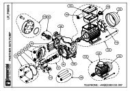
6. LEVEL INDICATOR – OIL WATCHMAN PLUS<br />
transmitter<br />
battery<br />
level<br />
sensor<br />
probe<br />
leak<br />
sensor<br />
probe<br />
receiver<br />
A. DESCRIPTION<br />
OIL WATCHMAN PLUS is an electronic measuring device designed for continuous monitoring of<br />
fuel or engine oil level in tank. The device comprises three elements:<br />
−<br />
−<br />
Transmitter, installed on the tank. In the case of tanks with volume 3,500 l and more it comprises<br />
two parts, connected with black wire. One part, with transmitter antenna and threaded battery<br />
connection, is installed in distributor box, whereas the second, a probe, is installed on the top of<br />
internal tank. In the case of tanks with volume 2,500 l and 1,200 l transmitter is made as a<br />
single piece, probe and transmitter antenna integrated, and installed inside distributor box, on<br />
the top of internal tank.<br />
Level probe (black plastic pipe inside the tank).<br />
− Leak sensor (located at the tank bottom, in the space between internal and external tank; it is<br />
connected with white wire to one of transmitter parts).<br />
Transmitter and receiver are one set and they are not interchangeable, i.e. this transmitter works<br />
only with specific receiver. In the event of permanent damage or loss of one of the parts remaining<br />
parts cannot be used with parts from different sets. Probes can work with various transmitterreceiver<br />
sets.<br />
Probe length is adjusted to height of given tank. Transmitter and probe measure the level of fuel in<br />
the tank and check for possible leaks. Information is then sent to receiver of OIL WATCHMAN<br />
PLUS. Receiver, in the form of plug with antenna and display, can be placed in any 230V power<br />
socket within 100 m distance from the tank. This distance can be much shorter if there are barriers,<br />
such as earth embankments, buildings, and electrical cables and appliances.<br />
Oil level data is sent to receiver over radio frequency and displayed on receiver screen.<br />
Measurement is updated ca. every 15 minutes.<br />
22
Oil level (regardless of tank volume) is shown in the form of digits:<br />
„0”- from 0% to 10% of total volume,<br />
…<br />
„9”- from 90% to 100% of total volume.<br />
Indicated oil level is laden with material error.(up to 10%) and provides only approximation on oil<br />
quantity in tank.<br />
B. ACTIVATION OF WATCHMAN PLUS<br />
OIL WATCHMAN PLUS sensors are installed in double-jacket tanks by TITAN EKO as a standard.<br />
Sensor activation procedure:<br />
− Place the receiver in 230V socket, possibly close to the tank. Best choose a single socket,<br />
where receiver can stay permanently. Avoid placing receiver near electrical appliances, such as<br />
microwave ovens, refrigerators or washing machines, since that may aggravate reception. Place<br />
antenna in possibly vertical position, at location free from obstructions. Display shows sensor<br />
serial number and then “r” or “L” which means that receiver is waiting for signal from transmitter.<br />
−<br />
After two minutes carefully screw in the battery (copper tube with threaded connection) to the<br />
transmitter in tank.<br />
− After few minutes more the receiver shall display current oil level in tank.<br />
Battery consumption depends on distance between the tank and the socket with Oil Watchman Plus<br />
receiver connected, as well as on type of materials between transmitter and receiver.<br />
WATCHMAN READING<br />
SPECIFICATION<br />
„L“<br />
Receiver waits for signal from transmitter in tank.<br />
RED DIODE BLINKING and “0”<br />
and ”1” digits are displayed<br />
Low oil level, place order for new supply.<br />
RED DIODE BLINKING and “r”<br />
is displayed every 5 sec.<br />
Blinking diode along with “r” symbol means that following last activation receiver does not<br />
receive signal from transmitter in tank. Power failure or electrical appliance is used nearby<br />
(radio, hairdryer, blender) can cause such reading. Receiver starts showing oil level after<br />
another update from transmitter. If that persists reset the system.<br />
1. Remove receiver from socket.<br />
2. Unscrew the battery from transmitter in tank.<br />
3. Check the cable connecting both transmitter parts in tank<br />
(clean and tighten concentric cable ends).<br />
4. Place receiver in 230 V socket.<br />
5. Wait 2 minutes. Carefully insert battery to transmitter.<br />
If nothing changes call the service.<br />
RED DIODE LIGHTS<br />
CONTINUOUSLY<br />
Leak – oil (or other fluid) in external tank. Check if the fluid is oil and fluid level (e.g. using<br />
flexible measuring tape) and then call the service.<br />
BAT LOW<br />
This information is displayed in place of level reading. It means reduction in voltage level of<br />
battery in transmitter occurred. Battery voltage shall be dropping at low temperatures. When<br />
battery temperature rises so will battery voltage and information shall no longer be<br />
displayed.<br />
Oil Watchman Plus shall continue to work normally at low battery voltage for weeks, without<br />
need for changing the battery.<br />
23
Displayed oil level blinking<br />
Battery used up – change battery.<br />
“F”<br />
Capital “C”<br />
Tank is full.<br />
When “F” symbol is displayed and tank is not full it means there is some fluid in the upper<br />
part of the probe.<br />
Dismantle transmitter, remove and clean the probe thoroughly.<br />
This symbol indicates transmitter – probe connection error. Check connection between<br />
transmitter and probe – if correct the probe is to be replaced.<br />
Small “c” and level displayed<br />
alternately<br />
Leak sensor defective. Check the sensor at the end of white cable leading from probe end.<br />
24
7. TANK OVERFILL PROTECTION<br />
In FuelMaster ® machines (with volume over 3,500 l) mechanic and electronic overfill protections are<br />
used. Mechanical protection is a Spill Stop device installed on machine inlet. When oil level in device<br />
reaches ca. half of the float height the inlet is almost completely cut-off. It shall allow only the flow<br />
rate of maximum 2,5 litre/min. The system works only with pressure refuelling of tank; required<br />
refuelling parameters:<br />
Minimum pressure: 150mbar (15kPa)<br />
Minimum flow: 35 litres/min.<br />
Maximum pressure: 3 bar (0.3Mpa)<br />
Maximum flow: 350 litres/min.<br />
Cut-off level:<br />
220mm<br />
Spill Stop – mechanic overfill protection<br />
Electronic protection is a probe installed on top of the tabk. Level of installed sensor determines<br />
where the maximum level is signalled. When the end of the probe is in the fluid rapid change in<br />
electric resistance occurs. That rapid change in resistance is used for generation of voltage surge for<br />
controlling the process of shutting down the tank valve.<br />
Electronic overfill protection<br />
25
8. MACHINE’S LITRE CAPACITY CHART<br />
BFM09000DG<br />
BFM09000DG<br />
BFM09000DG<br />
BFM09000DG<br />
Litres* Level [mm]<br />
350 ---------------- 100<br />
710 ---------------- 200<br />
1100 -------------- 300<br />
1480 -------------- 400<br />
1890 -------------- 500<br />
2250 -------------- 600<br />
2600 -------------- 700<br />
Litres* Level [mm]<br />
2970 --------------- 800<br />
3350 --------------- 900<br />
3740 --------------- 1000<br />
4100 --------------- 1100<br />
4490 --------------- 1200<br />
4850 --------------- 1300<br />
5210 --------------- 1400<br />
Litres* Level [mm]<br />
5570 ---------------1500<br />
5930 ---------------1600<br />
6300 ---------------1700<br />
6650 ---------------1800<br />
7000 ---------------1900<br />
7340 ---------------2000<br />
7700 ---------------2100<br />
Litres* Level [mm]<br />
8040 -------------- 2200<br />
8390 -------------- 2300<br />
8740 -------------- 2400<br />
9000 -------------- 2530<br />
9450 -------------- 2750<br />
9560 -------------- 2800<br />
BFM05000DG<br />
BFM05000DG<br />
BFM05000DG<br />
BFM05000DG<br />
Litres* Level [mm]<br />
180 --------------- 80<br />
360 --------------- 150<br />
540 --------------- 215<br />
725 --------------- 280<br />
900 --------------- 340<br />
1090 -------------- 410<br />
1270 -------------- 475<br />
Litres* Level [mm]<br />
1450 -------------- 530<br />
1635 -------------- 590<br />
1815 -------------- 660<br />
2000 -------------- 720<br />
2180 -------------- 805<br />
2360 -------------- 880<br />
2545 -------------- 945<br />
Litres* Level [mm]<br />
2725 --------------1010<br />
2905 --------------1090<br />
3090 --------------1160<br />
3270 --------------1220<br />
3450 --------------1300<br />
3630 --------------1370<br />
3810 --------------1440<br />
Litres* Level [mm]<br />
3995 ------------- 1510<br />
4175 ------------- 1595<br />
4360 ------------- 1675<br />
4540 ------------- 1750<br />
4720 ------------- 1830<br />
4905 ------------- 1905<br />
5000 ------------- 1940<br />
BFM03500DG<br />
BFM03500DG<br />
BFM02500DG<br />
BFM02500DG<br />
Litres* Level [mm]<br />
250 --------------- 125<br />
500 --------------- 205<br />
750 --------------- 295<br />
1000 -------------- 395<br />
1250 -------------- 495<br />
1500 -------------- 600<br />
1750 -------------- 700<br />
Litres* Level [mm]<br />
2000 -------------- 800<br />
2250 -------------- 905<br />
2500 -------------- 1010<br />
2750 -------------- 1125<br />
3000 -------------- 1225<br />
3250 -------------- 1350<br />
3500 -------------- 1450<br />
3750 -------------- 1590<br />
Litres* Level [mm]<br />
182 ----------------135<br />
363 ----------------225<br />
545 ----------------310<br />
726 ----------------385<br />
908 ----------------455<br />
1090 --------------520<br />
1271 --------------605<br />
Litres* Level [mm]<br />
1453 ------------- 670<br />
1634 ------------- 740<br />
1816 ------------- 810<br />
1998 ------------- 890<br />
2179 ------------- 970<br />
2361 ------------- 1070<br />
2497 ------------- 1125<br />
BFM01200DG<br />
BFM01200DG<br />
Litres* Level [mm]<br />
158 ----------------160<br />
258 ----------------235<br />
358 ----------------305<br />
458 ----------------435<br />
558 ----------------495<br />
658 ----------------555<br />
758 ----------------620<br />
Litres* Level [mm]<br />
858 --------------- 680<br />
958 --------------- 750<br />
1058 ------------- 825<br />
1158 ------------- 910<br />
* Approximate values<br />
Notes:<br />
− Data included in above charts are laden with error due to thermal expansion of polyethylene –<br />
material used for tank.<br />
− The end of suction hose is located a few centimetres above tank bottom, which causes<br />
occurrence of so-called “dead zone”, with volume of ca. 30% of nominal tank value. In the event<br />
of BFM05000DG tank it is ca. 150 litres. This way pump system of the machine is protected from<br />
sucking the oil from the very bottom, where sludge and other contaminants tend to settle.<br />
− Litre capacity measurement strip is not included with FuelMaster ® accessories offered by<br />
manufacturer.<br />
26
III.<br />
TRANSPORT AND STORAGE<br />
1. Transport and storage of machines is to ensure protection from mechanical damage. Machines<br />
can be transported only with their tanks emptied.<br />
2. Loading and unloading of machines is to be carried out using specialised equipment, such as<br />
forklift or crane, slings and belts.<br />
3. Transport of machines can be carried out with specially prepared vehicles, i.e. vehicles equipped<br />
with at least fixing points suitable for transport of tanks, allowing fixing the tank and protecting it<br />
from sliding during transport.<br />
4. Sliding or rolling the machines is prohibited. Never use projecting parts when lifting or sliding the<br />
machines.<br />
5. Loading space is to be smooth, with no sharp edges. Machines are to be secured against<br />
movement during transport.<br />
6. Machines can be stored outdoors, without specific limitations.<br />
Storage space is to be paved, even and without sharp edges.<br />
7. Lid and ferrule are to be tightly closed and secured during storage and transport. Electric cables<br />
and hose are to be coiled, filler nozzle placed in holder, distributor enclosure closed.<br />
8. Machine can be stored temporarily only when its tank is emptied.<br />
27
IV.<br />
GENERAL SETUP REQUIREMENTS<br />
Users of FuelMaster ® machines are obliged to follow domestic regulations concerning installation<br />
and operation of this machine, as well as recommendations by local fire-safety and environmental<br />
protection services.<br />
1. Installation and refuelling of machines displaying defects due to e.g. transport or storage, with<br />
visible signs of damages to ferrules, cracks to tank jacket, or with incomplete equipment, is<br />
forbidden.<br />
2. Machine is to be placed on flat (levelled), even and stable surface executed in non-flammable<br />
material. Base is to be at least 30 cm wider and longer than machine itself. Base thickness is to<br />
be at least 5 cm.<br />
3. Verify if parameters of power supply network are the same as required by pump motor.<br />
Connection to supply is to be carried out only by means of suitable, fully functional extensions, or<br />
permanent connection.<br />
4. Cables exposed to mechanic damages are to be secured by suspending them, placing them in<br />
protective pipe, or covering with protective strip.<br />
5. It is not allowed to place FuelMaster ® machines in garages, storage spaces adn other buildings,<br />
as well as on sidewalks and pedestrian passages.<br />
6. Space around the machine is to enable free and unobstructed traffic of vehicles.<br />
7. Machine is to be placed by access road with required width, with enough space for U-turn, and<br />
suitable for the load of fuel oil supplier mobile cistern.Potential obstructions, in the form of parked<br />
vehicles, overhead power lines, tree trunks, etc. are to be monitored and reduced on a day-today<br />
basis by machine operator. Operator is to ensure safety of oil supply, as well as free space<br />
around the machine for the purpose of periodic inspections and overhauls.<br />
8. It is forbidden to use open fire and smoke near the machine, as well as to use other media which<br />
might initiate combustion of fuel oil. A fire-safety sign “Using open fire and smoking forbidden” is<br />
to be placed at machine location.<br />
9. When using distributor with a pump powered with 230V AC voltage, electric wiring is to be<br />
carried out in accordance with pump manufacturer’s instructions and regulations in force.<br />
10. Machine location is to meet minimum distance requirements as in table below:<br />
Required minimum distances<br />
Object<br />
Distance<br />
Individual houses, apartment buildings, public buildings<br />
Other buildings, plot border, roads<br />
Sewers or heating system ducts;<br />
not applicable where the yard is equipped with linear drainage and oil<br />
separators<br />
> 15 m<br />
> 5 m<br />
> 5 m<br />
Water intakes, heating chambers, openings to premises with floor<br />
below adjacent ground level<br />
> 5 m<br />
Forrest border >10m<br />
28
Power line up to 1kV >3m<br />
Power line 15 kV to 30 kV >5m<br />
Power line 30kV to 110 kV >10m<br />
Power line above 110KV. >30m<br />
Devices with surface heating up to temperatures exceeding 100°C<br />
>0,5m<br />
11. When positioning and operating the machine never exceed below threshold noise values,<br />
expressed in equivalent level of A sound, for residential development areas:<br />
−<br />
67 dB – during the day,<br />
− 57 dB – during the night.<br />
12. No explosion hazard areas are specified for FuelMaster ® machines designated for storage and<br />
distribution of petroleum products cat. III.<br />
13. Protect the machine from direct sunlight, snow and rain. It is recommended that the machine is<br />
placed under suitable roofing.<br />
14. In the event of machines which are to be often<br />
moved or exposed to mechanic damages we<br />
recommend ordering protection frame (optional).<br />
15. Operator (owner) is obliged to provide a powder extinguisher 12 kg near the machine, and mark<br />
it in accordance with safety regulations - (“Fire Extinguisher”), and attach the sign “Using open<br />
fire and smoking prohibited”.<br />
29
V. ELECTRICAL SYSTEM<br />
Electrical system for FuelMastera ® is outside the scope of delivery and is to be provided by<br />
Customer. Electrical system is to be carried out in accordance with below instructions:<br />
1. EARTHING<br />
To successfully neutralize electrostatic charges on machines<br />
executed in plastic, as well as on connected equipment, and to<br />
ensure effective shock protection:<br />
a) W Place an earth electrode of copper or galvanized wire,<br />
cross-section 16 mm 2 , near the machine, to bring<br />
electrostatic charges to earth.<br />
Connect the following to earth electrode:<br />
−<br />
oil unloading system when refuelling the machine,<br />
− earthing screw outside distributor enclosure.<br />
b) Connection to be executed with earthing cable with<br />
resistance below 10Ω.<br />
c) PE protection cable (yellow and green) of pump power<br />
supply to be connected to the existing power mains.<br />
2. TEMPORARY POWER SUPPLY<br />
When the machine is often moved it is allowed to use extensions with suitable parameters.<br />
The machine is delivered with power cord and plug with earthing pin, which can be connected to<br />
extension cable. Alternatively the plug can be replaced with permanent plug (with suitable IP),<br />
installed on distributor enclosure.<br />
Extension is to have the following parameters:<br />
− minimum cross-section 3x2.5 mm 2 ,<br />
−<br />
−<br />
−<br />
copper wire - line,<br />
PE pin (earthing),<br />
protection index: at least IP65,<br />
− extension feeder line cut-out value is to be C16A (value of trip current: 16 A with C type<br />
characteristics),<br />
− fully functional; with no signs of wear, no damage to isolation, no loose contacts, no signs of rep<br />
air, etc.<br />
When connecting extension make sure that pump switch is in OFF position.<br />
NOTE:<br />
Protect extension connection from humidity. When the machine is in a standstill or not<br />
operating (at night) power cord is to be disconnected, unless the machine is working.<br />
30
3. PERMANENT POWER SUPPLY<br />
When the machine is not going to be moved it is recommended<br />
that permanent power cord is installed, going directly to pump<br />
electrical box. The following requirements are to be met:<br />
− Power mains 230V is to be connected to control box in<br />
accordance with wiring diagram, by qualified electrician. Mains<br />
is to meet the requirements specified by pump manufacturer<br />
and provisions of regulations in force.<br />
− Use power cord 3 x 2.5mm 2 .<br />
− Mains connection is to be protected with suitable cut-out.<br />
TO MOTOR<br />
SINGLE PHASE<br />
CAPACITOR<br />
Pump electrical box diagram<br />
In the event of power network TN-C type, with only two power wires available – phase (black or<br />
brown wire) and working zero (blue wire), it is recommended that PE wire (yellow and green) is<br />
connected to power supply working zero terminal (blue wire).<br />
Tank electrical box<br />
Power supply box, type TN-C<br />
Terminals<br />
Power supply box<br />
Black or Brown<br />
Blue<br />
Electrical Schemat connection podłączenia between elektrycznego the machine urządzenia<br />
and z rozdzielnią main switching główną station w układzie with power zasilania supply TN-C<br />
system TN-C<br />
31
In the event of power network TN-S type, with three power wires available – phase (black or<br />
brown wire) and working zero (blue wire), and protection wire (yellow and green), it is recommended<br />
that PE wire (yellow and green) is connected to powers supply PE wire (yellow and green).<br />
Tank electrical box<br />
Power supply box, type TN-C<br />
Terminals<br />
Black or Brown<br />
Power supply box<br />
Blue<br />
Yellow and green<br />
Electrical connection between the machine<br />
and main switching station with power supply system TN-S<br />
Machine overcurrent protection<br />
In addition to protection in pump electrical box also overcurrent protection in power supply box is to<br />
be employed. Cut-out value is to be C16A (value of trip current: 16 A with C type characteristics).<br />
NOTE:<br />
Permanent connection between the machine and power supply box is to be carried out by<br />
electrician with valid license, issued by relevant organisation, for the scope of operations<br />
performed.<br />
32
VI.<br />
GENERAL SAFETY PRINCIPLES<br />
1. Material in store.<br />
The basic source of information concerning hazardous material is Material Safety Data Sheet.<br />
Refer to fuel oil supplier to obtain MSDS concerning purchased oil.<br />
Fuel oil is a mixture of petroleum hydrocarbons, with carbon atoms content 9 to 25, and<br />
additives.<br />
2. Major hazards caused by stored material (fuel oil) and methods of their reduction:<br />
− avoid repeated or long exposure of skin to fuel oil,<br />
− always wear protective gloves when refuelling the machine,<br />
− follow the general hygiene principles; wash contaminated body parts immediately using<br />
water and soap,<br />
− do not eat/drink when operating the machine,<br />
− do not use open fire and do not smoke when operating the machine,<br />
− oil fumes are harmful when inhaled, and are likely to cause irreversible damage to health;<br />
exercise extreme caution when using fuel oil,<br />
− avoid contact with eyes, if possible wear protective goggles with lateral screens; exposure is<br />
likely to cause health risk,<br />
− fuel oil has toxic effect to aquatic and land animals; it is likely to cause long-term adverse<br />
effects to natural environment,<br />
− increases fire hazard; fumes create explosive mixture with air; since they are heavier than air<br />
they tend to accumulate near premises floors.<br />
3. Maintain order at the machine workplace. Provide suitable lighting. Supervision of the tank is the<br />
responsibility of owner (or hirer, if the machine is rented).<br />
The machine can be operated by person 18 years old, who familiarized himself/herself with<br />
operation manual and operational safety principles. Children and third persons are to stay away<br />
from the machine workplace.<br />
4. Owner and operator of the machine is to take appropriate safety measures, with regard to nature<br />
and reasonably predictable risks, to prevent damages/injuries, and, if necessary, to reduce their<br />
consequences. In the event of direct hazard to public safety, owner and operator are to notify<br />
emergency services immediately, and provide them with information required by such services to<br />
perform their functions. Obligations are specified by relevant domestic regulations.<br />
5. In the event of machine failure (leaks from tank, electric shock), person who observed such<br />
failure is obliged to:<br />
− stop work in hazardous area,<br />
− switch off distributor power supply,<br />
− immediately assist injured persons – having made sure that entrance to hazard zone is safe,<br />
− notify his/her superior,<br />
− person with management capacity responsible for storage or hazard area , or person<br />
assigned by such person, is managing rescue activities, and, if necessary, notifies firebrigade,<br />
− in the event of leak to pump its content to another machine,<br />
− notified authorised service.<br />
6. In the event of machine utilization it is to be disassembled to basic parts and then recycled.<br />
7. Beware of electric shock. Strictly follow the instructions included in this manual.<br />
8. Follow plant’s fire-safety and H&S regulations.<br />
33
VII. OPERATIONAL RECOMMENDATIONS<br />
Portable fuel oil distribution machine is designed and executed for durability, reliability and lowmaintenance<br />
during operation. Due to the type of fluid stored and potential hazards to environment,<br />
the following recommendations are to be followed:<br />
1. REFUELLING OF MACHINES<br />
Oil is to be fed from mobile tanks or other means of transport of hazardous materials class III.<br />
Unloading is to be carried out only via tight connection!<br />
Feeder lines of machines with volume from 3,500 litres can be have the following fittings:<br />
Dry fitting 2”<br />
(no ball valve requried<br />
prevents leakage)<br />
Eurofitting 2” Camlock 2”<br />
1. The machine can be refilled only to half of its rated volume, which is 95% of maximum volume.<br />
Never allow overfilling!<br />
2. Both loading and unloading of oil is to be carried out under strict supervision of properly trained<br />
person.<br />
3. Do not store contaminated fuel oil, or other oil, e.g. biodiesel, hydraulic oil, etc., as it may lead to<br />
contamination of the machine and damage to pumping system. Operator is to be able to<br />
document origin and ignition temperature of stored fuel oil.<br />
4. In justified cases it is also required that person supervising refuelling of the machine wear brightcoloured<br />
clothing and hardhats. In addition, depending on situation, mobile tank driver is to wear<br />
personal protective equipment, such as boots, goggles, gloves, ear protection, raincoats, etc. as<br />
provided for this type of activities.<br />
5. Fuel oil delivery place is to be secured for the period of refuelling with safety signs, warning<br />
lights, etc. Safety measures are to be used particularly when mobile tank occupies the whole<br />
street width and obstructs normal traffic. The same safety measures are to be used when mobile<br />
tank hoses occupy the sidewalk.<br />
6. Prior to refuelling check the condition of inlet ferrule, oil level in the machine, and cleanness of<br />
machine interior. Check if the machine is stable and if it is not damaged. Damages and other<br />
irregularities make the machine unfit for refuelling.<br />
7. It is recommended that mobile tanks with maximum level sensor are used.<br />
8. When the tank is situated in a large distance from mobile tank, there should be one more person<br />
supervising refuelling.<br />
9. Maximum allowed speed of refuelling the tank is 350 l/min.<br />
34
2. REFUELLING OF VEHICLE<br />
−<br />
During first refuelling the whole suction line contains<br />
air. Start the pump, place filler nozzle in vehicle tank<br />
inlet, and keep it open all the time to allow venting of<br />
air. Fuel can appear after maximum 2 minutes. Upon<br />
completion of refuelling first stop the pump, and then,<br />
when flow stops, release the handle of filler nozzle<br />
valve. Another sequence shall cause pressurized oil to<br />
stay in distribution hose, which is not desired.<br />
− Prior to starting operation read operations manual of<br />
pump and flowmeter.<br />
− Never operate the machine at temperatures below -<br />
20°C and above +40°C, nor in bad weather conditions,<br />
such as rain, strong wind, etc.<br />
−<br />
!!! Prior to starting operation make sure there is<br />
fuel in the machine. !!!<br />
Working “dry” shall cause damage to pump.<br />
− Maximum allowed time of pump operations with distributor filler nozzle closed is very short (2 – 3<br />
minutes). After the use make sure the pump is shut off.<br />
−<br />
−<br />
Perform visual inspection of the machine condition.<br />
Make sure that distribution filler nozzle with automatic cut-off valve and flexible hose is in good<br />
condition, without visible signs of external damage.<br />
− Drive the vehicle to be refuelled near the machine, to the distance which allows effective<br />
refuelling operation. Turn off the engine of refuelled vehicle.<br />
−<br />
It is forbidden to stay inside the vehicle being refuelled; leave the vehicle.<br />
− Drive the vehicle away immediately after refuelling. It is forbidden to park vehicles near the<br />
distributor.<br />
−<br />
It is forbidden to park more than one vehicle near the machine. Driver of vehicle is obliged to<br />
keep safe distance (min. 5 metres).<br />
− It is forbidden to park vehicle in a way obstructing possible emergency evacuation from firehazard<br />
area.<br />
−<br />
−<br />
−<br />
−<br />
−<br />
In the event of spilling fuel onto or near the machine immediately remove the spill, before the<br />
machine is restarted.<br />
In the event of observing leak in machine tank immediately pump the oil to another tank; notify<br />
machine manufacturer.<br />
Never cover the venting ferrule, clean it regularly.<br />
Disconnect the machine form power supply when not in use.<br />
In the event of incorrect operation order have the machine repaired.<br />
35
VIII. MACHINE MAINTENANCE<br />
Maintenance activities and schedule is to be carried out as per table below:<br />
Item Activity Frequency<br />
1<br />
Check if machine accessories are complete.<br />
Replace or tighten all damaged or loose parts.<br />
before operation<br />
2 Check condition of electrical system and connections. before operation<br />
3 Earthing condition, shock-protection effectiveness, continuity of PE wire. ●<br />
4 Check functioning of level sensor. ●<br />
5 Check and clean mesh filter in pump and at the end of suction hose. ●<br />
6<br />
In the event of contamination clean flowmeter measuring chamber. In the event<br />
of digital flowmeter, clean also filter.<br />
●<br />
7 Calibrate flowmeter. ●<br />
8 Check for leaking joints. ●<br />
9 Check pump venting duct.<br />
10 Check condition and efficiency of distribution system. ●<br />
11 Clean the accessories. ●<br />
14<br />
12<br />
13<br />
Check and tighten, if necessary, all joining elements, e.g. screws, bolts, nuts,<br />
etc.<br />
Check and if necessary clean the interior of tank.<br />
Clean the machine from the outside.<br />
Proof metallic elements against corrosion.<br />
Rubber parts (distribution hose, filler nozzle guard) to be protected with rubber<br />
protection agents.<br />
●<br />
●<br />
periodic<br />
15 Check machine marking. ●<br />
„●”<br />
means every 6 months or every 50,000 litres of fuel, depending which date is earlier.<br />
36
IX.<br />
TROUBLESHOOTING<br />
Item DEFECT CAUSE ADVICE<br />
1 Leak Damaged sealing.<br />
Flowmeter miscalibration.<br />
Dismantle connection, install new<br />
sealing.<br />
Perform recalibration.<br />
2 Insufficient accuracy.<br />
Contaminated flowmeter chamber.<br />
Air content in oil.<br />
Dismantle and clean flowmeter<br />
chamber.<br />
Find and remedy leak in<br />
pump/suction line.<br />
Blocked or contaminated filter at the end of<br />
suction hose or other part of suction line.<br />
Locate and remove contamination.<br />
3 Reduced flow rate.<br />
Air in pump, air in oil.<br />
Irregular pump operation.<br />
Vent pumping system, check<br />
tightness of suction line.<br />
Check supply voltage.<br />
Check voltage of power.<br />
Blocked gears or contaminated filter in<br />
digital flowmeter.<br />
Clean measuring chamber, filter.<br />
Obstructed or blocked measuring chamber<br />
in analogue flowmeter.<br />
Clean measuring chamber.<br />
4<br />
Increase in noise level<br />
during pump operation.<br />
Air in oil.<br />
Find and remedy leak.<br />
No power supply.<br />
Ensure proper power supply.<br />
5 Motor is not rotating.<br />
Rotor jammed.<br />
Check rotating parts of pump and<br />
motor.<br />
Pump thermal protection tripped.<br />
Wait until motor cools down.<br />
6<br />
Digital flowmeter counter<br />
does not count units<br />
despite displaying<br />
correct flow rate value.<br />
Gears incorrectly installed after cleaning.<br />
Reinstall gears correctly.<br />
7<br />
Digital flowmeter counter<br />
does not count units.<br />
Incorrect installation of gears.<br />
Defective reed relay.<br />
Reinstall gears correctly.<br />
Replace reed relay.<br />
8 Defective level indicator. See section “Level indicator”.<br />
Too high flow rate.<br />
Reduce flow rate.<br />
9<br />
Vibrations in refuelling<br />
line during refuelling.<br />
Line incorrectly mounted.<br />
Strong throttling due to defective<br />
connection or Spill Stop.<br />
Mount the line correctly.<br />
Replace defective part.<br />
37
X. GUARANTEE TERMS<br />
1. Firma Titan Eko Sp. z o.o. issues the following guarantees for FuelMaster ® machine:<br />
- 10 years for tightness of double-jacket tank,<br />
- 1 year for distribution system (pump, flowmeter, hoses, etc.),<br />
- 1 year for sensors: Watchman Plus oil level and leak sensor, maximum level sensor, and other\<br />
accessories installed in tnaks.<br />
2. In the event of failure please contact Titan Eko Service Department , phone no. +61 814 44 28.<br />
Notifications to be sent to fax no. +61 814 54 99 or to e-mail: serwis@titan-eko.pl .<br />
3. When reporting failure the first step is to send Service Order (Defect Report Sheet) in writing (e.g. by fax),<br />
using the form included in Operation Manual attached with each machine (we recommend to photocopy the<br />
form so that it could be reused).<br />
4. Guarantee and post-guarantee servicing of FuelMaster ® machines is provided by authorized Titan Eko<br />
service Centre – Rohe Polska Sp. z o.o.<br />
5. For details of servicing contact directly ROHE Service Centre, mobile 507 130 912, fax no. +32 250 54 62.\<br />
6. Defects revealed within guarantee period shall be remedied within two weeks following the date of report in<br />
writing.<br />
7. Guaranteed response time to notification is 48 hours on business days.<br />
8. Defect reports are received 24/7. Report acceptance time for reports sent on 4 p.m. to 8 a.m., and on<br />
holidays and weekends, is 8 a.m. the following business day.<br />
9. Aiming at improvement of mechanic parts of tanks we suggest periodic inspection after first 6 months of<br />
usage, or after 50,000 litres of fuel is pumped through the tank (whichever comes first).<br />
10. Inspection is voluntary, however failure to perform such inspection may in extreme cases lead to revoking<br />
guarantee for mechanic components of tank. Inspection order is to be placed directly with company ROHE<br />
Polska (mobile 507 130 912, fax no. +32 250 54 62).<br />
11. If defect disclosed during guarantee period is due to improper operation or installation of the machine (see<br />
clauses 6 and 7 of this Manual), or if defect is disclosed after expiration of guarantee period, reporting party<br />
shall be charged with servicing costs.<br />
12. By placing order for service Purchaser agrees to be charged for services outside the scope of guarantee<br />
offered by Service Centre authorized by manufacturer. Titan Eko Sp. z o.o. verifies reports, supports<br />
purchaser of service, and authorized service centre, to ensure most effective performance of order;<br />
company is not however the party in settlements between Purchaser and service Contractor.<br />
13. Guarantee is exclusive of standard maintenance, such as cleaning of filters, changing of batteries,<br />
calibration (accuracy adjustment) of flowmeters. When observing inaccuracies in flowmeter indications,<br />
perform calibration in accordance with included instruction.<br />
14. Purchaser forfeits guarantee rights in following cases:<br />
- damages due to improper installation and operation,<br />
- failure to ensure maintenance, mechanic damages, acts of vandalism,<br />
- defects due to unauthorized repairs or modifications,<br />
- changing product purpose.<br />
15. Company Titak Eko Sp. z o.o. is not responsible for damages due to operation of the machine in a way<br />
contrary to manufacturer’s instructions and regulations in force.<br />
You can find serial<br />
number of machine in<br />
these locations<br />
38
DEFECT REPORT SHEET<br />
SERVICE ORDER<br />
Date: ...........................<br />
Attn:<br />
Commercial Fuel Solutions Ltd<br />
Unit 22 Badgers Way<br />
Buckingham, MK18 7EQ<br />
tel.:+44 (0)845 688 9755<br />
fax:+44 (0)845 688 9744<br />
“R” DOCUMENT<br />
NUMBER ...........................................<br />
DATE ...............................................<br />
ADJUSTMENT NOTE<br />
NUMBER ...........................................<br />
DATE ...............................................<br />
“D” DOCUMENT<br />
NUMBER ...........................................<br />
DATE ...............................................<br />
Titan Eko Client:<br />
COMPANY:<br />
ADDRESS:<br />
CONTACT:<br />
phone: ………………………………. fax: ............................................<br />
Detailed address of product location:<br />
COMPANY: ……...………………………………………........................<br />
ADDRESS: …..…………………………………………........................<br />
CONTACT ……………………………......................<br />
phone: ………………………………. fax: ............................................<br />
Date and time when the product can be services/collected:<br />
......................................................................................................<br />
SENT BY: ........................<br />
NUMBER ...........................................<br />
DATE ..............................................<br />
Serial no.:<br />
Date of purchase:<br />
Guarantee card no.:<br />
Fuel-Mastera type* BFM09000DG BFM05000DG BFM03500DG BFM02500DG BFM01200DG<br />
Flowmeter type*<br />
* Select correct<br />
K33<br />
(analogue)<br />
K600<br />
(digital)<br />
MC CUBE<br />
(PIN codes)<br />
PETROSOLO<br />
(GUM verification)<br />
REASON OF REPORT/DESCRIPTION OF DEFECT:<br />
Name .................................................................... Signature …………...............................................<br />
NOTE: If it is determined that defect disclosed during guarantee period is due to improper use or installation of the product, or defect<br />
occurred after expiration of guarantee period, reporting party shall be charged with service-related costs.<br />
Immediate remedies:<br />
Preventive measures:<br />
Responsible person:<br />
Date of closure:<br />
Signature:<br />
Responsible person:<br />
Date of closure:<br />
Signature:<br />
DECISION (Sales Administration Dept.):<br />
Name .................................................................... Signature …………..................................................<br />
39