hi\\arbetsfiler\instruktioner\tapflo\pumpar\ct
Tapflo CT Series Pumps :: Commercial Fuel Solutions Ltd
Tapflo CT Series Pumps :: Commercial Fuel Solutions Ltd

Create successful ePaper yourself
Turn your PDF publications into a flip-book with our unique Google optimized e-Paper software.
Models<br />
CTAA-03<br />
CTBB-07<br />
CTCC-15<br />
CTCC-22<br />
CTCE-22<br />
CTDD-40<br />
CTDF-40<br />
CTDF-55<br />
CTDG-55<br />
CT series<br />
English<br />
Instruction manual<br />
centrifugal pumps<br />
Pumps in electro polished<br />
stainless steel AISI 316L<br />
Edition 1/2005 <strong>hi\\arbetsfiler\instruktioner\tapflo\pumpar\ct</strong> eng\ct instruction english.pmd<br />
STOP<br />
Instructions for installation, start up, operation,<br />
maintenance and repair<br />
Spare parts<br />
Read this instruction manual carefully, before<br />
you install and operate the pump
CONTENTS<br />
Chapter Content Page<br />
Contents 2<br />
CE certificate 3<br />
0 General 4<br />
0.1 Introduction 4<br />
0.2 The warning symbols 4<br />
0.3 Qualification and training of personnel 4<br />
0.4 Health & safety 5<br />
1 Installation 6<br />
1.1 Receiving inspection 6<br />
1.2 Storage 6<br />
1.3 Foundation 6<br />
1.4 Piping connections 6<br />
1.4.1 Discharge pipe 6<br />
1.4.2 Suction pipe 6<br />
1.5 Example of installation 7<br />
1.6 Instruments 8<br />
1.7 Motor connection 8<br />
2 Operation 9<br />
2.1 Start-up 9<br />
2.1.1 Starting the pump 9<br />
2.2 Stopping the pump 9<br />
2.3 Cleaning and disinfection 10<br />
2.3.1 Cleaning procedure 10<br />
3 Maintenance 11<br />
3.1 Inspections 11<br />
3.2 Location of faults 11<br />
3.3 Assembly and disassembly 12<br />
3.3.1 Pump casing - assembly and disassembly 12<br />
3.3.2 Impeller and back casing - disassembly 13<br />
3.3.3 Mechanical seal - assembly and disassembly 13<br />
3.3.4 Assembly of impeller 14<br />
3.3.4 Replacement of motor 14<br />
3.4 Mounting torques and dimensions of screws/nuts 14<br />
4 Spare parts 15<br />
4.1 Spare part drawing CT pumps 15<br />
4.2 Spare part list 15<br />
4.3 Stocking recommendation 16<br />
4.4 Pump code 16<br />
5 Data 17<br />
5.1 Performance curves 17<br />
5.2 Technical data and limits 17<br />
5.3 Dimensions 18<br />
6 Warranty & repair 19<br />
6.1 Returning parts 19<br />
6.2 Warranty 19<br />
6.3 Warranty form 20<br />
Instruction manual CT centrifugal pumps 2
CE CERTIFICATE<br />
Declaration of conformity<br />
Machinery directive 89/392/EEC, Annex 2A<br />
Tapflo AB declares that:<br />
Product name:<br />
Models:<br />
Centrifugal pumps<br />
CT…<br />
Is in conformity with the essential health and safety requirements and technical<br />
construction file requirements of the EC Machinery directive 89/393/EEC with<br />
amendments 91/368/EEC, 93/94 EEC and 93/68 EEC.<br />
Manufacturer:<br />
Tapflo AB<br />
Address: Filaregatan 4<br />
S-442 34 Kungälv<br />
Sweden<br />
Tapflo AB, january 1st 2004<br />
Börje Johansson<br />
Managing director<br />
Instruction manual CT centrifugal pumps 3
0. GENERAL<br />
0.1 Introduction<br />
CT is an open impeller centrifugal pump, manufactured from stainless steel AISI 316L. With excellent<br />
electro polished surfaces, high finish and mechanical strength, the CT range meet the demands<br />
from a variety of today’s industries.<br />
With proper attention to maintenance, CT pumps will give efficient and trouble free operation. This<br />
instruction manual will familiarise operators with detailed information about installing, operating and<br />
maintaining the pump.<br />
0.2 The warning symbols<br />
The following warning symbols are present in this instruction manual. This is what they say.<br />
STOP<br />
This symbol stands next to all safety instructions in this instruction manual where<br />
danger to life and limb may occur. Observe these instructions and proceed with utmost<br />
caution in these situations. Inform also other users of all safety instructions. In addition<br />
to the instructions in this instruction manual, the general safety and accident prevention<br />
regulations must be observed.<br />
This symbol signals possible danger caused by the presence of electric fields or live<br />
wires.<br />
!<br />
This signal stands at points in this instruction manual of particular importance for<br />
compliance with regulations and directives, for correct work flow and for the prevention<br />
of damage to and destruction of the complete pump or its subassemblies.<br />
0.3 Qualification and training of personnel<br />
STOP<br />
The personnel in charge of installation, the operation cycle and maintenance of the pumps we produce<br />
must be qualified to carry out the operations described in this manual. Tapflo shall not be held<br />
responsible for the training level of personnel and for the fact that they are not fully aware of the<br />
contents of this manual.<br />
Instruction manual CT centrifugal pumps 4
0. GENERAL<br />
0.4 Health & safety<br />
Electric safety<br />
Do not carry out any maintenance operation on the pump while it is running or before it has been<br />
disconnected from the power supply. Avoid any danger caused by electric power (for details see<br />
current regulations in force). Check that electrical specifications on the data plate are equivalent to<br />
the power supply to which it will be connected.<br />
STOP<br />
Chemical hazards<br />
Avoid pumping liquids, even in different moments that may cause chemical reactions without having<br />
cleaned the pump.<br />
!<br />
Dry running<br />
Do not start nor carry out running tests before filling the pump with liquid. Always avoid the dry<br />
operation of the pump. Start the pump when it is completely filled with the delivery valve almost fully<br />
closed, limiting this condition to the time that is strictly necessary to start the pump.<br />
STOP<br />
Temperature hazards<br />
The cold or hot parts of the machine must be protected to avoid accidental contacts.<br />
STOP<br />
Rotating parts<br />
Do not tamper with the protection of the rotating parts, do not touch or approach rotating parts in<br />
movement.<br />
STOP<br />
Noise level<br />
CT pumps, including the motor, in normal operating conditions produce a sound level below 80<br />
dB(A). The major sources of noise are: liquid turbulence in the plant, cavitation or any other abnormal<br />
operation that do not depend from the pump construction nor the pump manufacturer. The user must<br />
provide suitable protective means if the sources of noise could produce a harmful noise level for<br />
operators and for the environment (in compliance with current regulations).<br />
STOP<br />
Cleaning & disinfection<br />
Cleaning and disinfection of the pump system is of greatest importance when the pump is used in a<br />
food process installation. Use of a pump system that is NOT cleaned or disinfected can cause<br />
contamination of the product.<br />
Instruction manual CT centrifugal pumps 5
1. INSTALLATION<br />
1.1 Receiving inspection<br />
Although precaution is taken by us when packing and shipping, we urge you to carefully check the<br />
shipment on receipt. Make sure that all parts and accessories listed on the packing list are accounted<br />
for. Immediately report any damage or shortage to the transport company and to us.<br />
1.2 Storage<br />
If the equipment is to be stored prior to installation, place it in a clean location. Do not remove the<br />
!<br />
protective covers from the suction, discharge and air connections, which have been fastened to keep<br />
pump internals free of debris. Make sure to clean the pump thoroughly before installation.<br />
1.3 Foundation<br />
The pump-motor unit must stand on and be fixed to a sufficiently rigid structure that can support the<br />
!<br />
entire perimeter on which the unit stands. The foundation on a firm bottom are the most satisfactory.<br />
Once the pump is in position, adjust level with metal shims between the feet and the surface on<br />
which it stands. Check that the feet of the pump-motor unit stand well on each of them. The surface<br />
on which the foundation stands must be flat and horizontal. If the unit is fitted on a steel structure,<br />
make sure that it is supported so that the feet do not warp. In any case, it is advisable to fit some<br />
antivibration rubber pieces between the pump and the brickwork.<br />
As the pump is close-coupled type, pump-motor alignment is not required.<br />
1.4 Piping connections<br />
A pump is generally part of a piping system that can include a number of components such as<br />
valves, fittings, filters, expansion joints, instruments, etc. The way the piping is arranged and the<br />
positioning of the components has a great influence on operation and the operating life of the pump.<br />
! The pump cannot be used as a support for the components connected to it.<br />
The flow of liquid from the pump must be as even as possible. It is advisable to avoid any tight bends<br />
or drastic reductions of diameters that may cause flow resistance in the plant. In case of diameter<br />
reduction, it is advisable to use appropriate conical reductions (possibly eccentric on suction side<br />
and concentric on delivery side) at changes of diameter and at a minimum distance from pump inlets<br />
of five diameters.<br />
1.4.1 Discharge pipe<br />
A nonreturn valve and a shutoff/regulation valve are normally fitted on the discharge side.<br />
The nonreturn valve protects the pump from any backflow. The shutoff/regulation valve excludes the<br />
!<br />
pump from the line and adjusts output. Never adjust flow-rate using the valve on the suction pipe.<br />
1.4.2 Suction pipe<br />
The suction piping is very important for the correct operation of the pump group. It must be as short<br />
and as direct as possible. If a longer suction line is unavoidable, the diameter should be large<br />
!<br />
enough, i.e. at least as the inlet connection on the pump, to ensure less flow resistance. In any<br />
case, suction must be carried out properly avoiding any air locks.<br />
!<br />
The CT pumps are single-stage centrifugal type, thus not self-priming. It will therefore always be<br />
necessary to install a bottom valve in all cases when the static height of the liquid is lower than the<br />
suction height of the pump. The suction piping must be without air inlets that are more probable with<br />
long suction lines or if suction occurs with negative head. Critical points in these terms are also the<br />
seals between flanges and the seals of the valve stems. Even some small air let into the suction line<br />
cause serious operating problems that can make the pump stop.<br />
Instruction manual CT centrifugal pumps 6
1. INSTALLATION<br />
1.5 Example of installation<br />
1) YES: gate valve (may also be near pump in the case of long piping)<br />
2) With positive head: tilt of piping towards pump<br />
3) YES: line strainer if particles are present<br />
4) NO: air pockets: the circuit must be short and straight<br />
5) YES: pipe fixing parts<br />
6) Suction line as short and direct as possible<br />
7) YES: check valve (especially for long vertical or horizontal pipes; compulsory with parallel<br />
pumps)<br />
8) YES: adjusting gate valve on outlet<br />
9) Bends placed after valves and instruments<br />
10) YES: attachment for gauge or safety pressure switch<br />
11) NO: elbow joints (and other parts) on the pump (discharge and suction lines)<br />
12) With negative suction lift: tilt of piping towards suction tank<br />
13) YES: check valve (with negative suction lift)<br />
14) YES: strainer if particles are present<br />
15) Suction head varies according to flow in order to prevent windage<br />
16) Suction head<br />
17) Immersion depth<br />
18) YES: expansion joint (indispensable with long pipes or hot liquids) and/or anti-vibration facility<br />
during discharge and suction; anchored near to pump<br />
19) YES: pipe discharge (completely sealed), discharge valve shut during normal operations<br />
20) YES: overcoming obstacles at lower depths<br />
21) Fix the pump by the fixing holes provided: the supports must be level<br />
22) YES: drainage channel around base<br />
Instruction manual CT centrifugal pumps 7
1. INSTALLATION<br />
1.6 Instruments<br />
In order to ensure a reasonable control of the performance and the conditions of the pump installed,<br />
!<br />
we recommend using the following instruments:<br />
- a pressure-vacuum gauge on the suction piping;<br />
- a pressure-vacuum gauge on the delivery piping.<br />
The pressure intakes must be made on straight pieces of piping at minimum five diameters from the<br />
pump inlets. The pressure gauge on delivery must always be fitted between the pump and the<br />
shutoff/regulation valve. The output can be read on the pressure, transformed into meters and then<br />
compared with the typical curves.<br />
Electric power<br />
The electric power absorbed by the motor can be measured with wattmeters.<br />
!<br />
Optional instruments<br />
The optional instruments can advise of abnormal operating conditions of pumps, such as: valves<br />
closed accidentally, missing liquid, overloads, etc.<br />
Thermometer<br />
If the temperature of the pumped liquid can be a critical element, provide a thermometer (preferably<br />
on suction).<br />
1.7 Motor Connection<br />
An expert electrician must always carry out the electrical connection. Compare the power supply<br />
with the data plate specifications and then choose a suitable connection. The type of connection is<br />
stated on the motor data plate that can be Y (star) or D (Delta), according to the power supply of the<br />
motor (see figure).<br />
Star connection Y<br />
Delta connection D<br />
Follow the prescriptions of the local electricity board for the connection. In no case connect the<br />
electrical motors directly to mains but also fit in between a suitable electric switchboard equipped<br />
with a knife switch and suitable safety devices. Safety devices against overloads must protect the<br />
motors. Make sure that the motor has suitable grounding and that it has been connected properly.<br />
Instruction manual CT centrifugal pumps 8
2. OPERATION<br />
2.1 Start-up<br />
- Check manually that the motor is free to turn, moving the motor cooling fan.<br />
- Make sure that the piping is not clogged and is free from residues or foreign objects. Make sure<br />
that the liquid flows regularly into the pump.<br />
!<br />
- The pump and piping connected to it, at least the suction pipe, must be full of liquid. Any air or gas<br />
must be carefully released. In case of suction with negative head, fill the suction piping and check<br />
how the bottom valve works. It must guarantee that the liquid must not flow back, emptying<br />
therefore the suction pipe with consequent disconnection of the pump.<br />
- The suction shutoff valve (if any) must be completely open.<br />
- The shutoff/regulation valve on the discharge side must be almost completely closed.<br />
!<br />
STOP<br />
- The motor must turn in the same direction as the arrow shown on the pump. The direction of<br />
rotation is always clockwise looking at the pump from the motor side; check by starting briefly,<br />
then looking at the direction of rotation of the motor fan through the fan lid. If it is wrong, the motor<br />
must be stopped immediately. Change the connection to the terminals of the electric motor<br />
(chapter 1.7) and repeat the procedure described above.<br />
- Any auxiliary connections must all be connected.<br />
2.1.1 Starting the pump<br />
Start the electric motor and open the discharge adjustment/shutoff valve gradually until the desired<br />
output has been reached. The pump must not turn more than two or three minutes with discharge<br />
!<br />
closed. A longer operation in these conditions can damage the pump seriously.<br />
If the pressure shown on the pressure gauge on the discharge piping does not increase, turn off the<br />
pump immediately and release pressure carefully. Repeat the connection procedure.<br />
!<br />
If there are changes of flow-rate, head, density, temperature or viscosity of the liquid, stop the pump<br />
and get in touch with our technical service.<br />
2.1.2 Re-starting after power shutoff<br />
In case of accidental stopping, make sure that the non-return valve has prevented backflow and<br />
check that the motor cooling fan has stopped. Start the pump again following the instructions of<br />
chapter 2.1.1 ”Starting the pump”.<br />
If the pump intakes from a lower level, it can unprime during the standstill and therefore you must<br />
check again before starting that the pump and the suction piping are full of liquid.<br />
2.2 Stopping the Pump<br />
It is advisable to close the discharge adjustment/shutoff valve gradually and stop the motor immediately<br />
!<br />
after. The reverse sequence is not recommendable, especially with larger pumps or longer delivery<br />
piping. That is to avoid any problems due to water hammering. If a suction shutoff valve has been<br />
installed, it is advisable to close it completely.<br />
Instruction manual CT centrifugal pumps 9
2. OPERATION<br />
2.3 Cleaning and disinfection<br />
STOP<br />
Cleaning and disinfection of the pump system is of greatest importance when the pump is used in a<br />
food process installation. Use of a pump system that is NOT cleaned or disinfected can cause<br />
contamination of the product. The cleaning cycles as well as chemicals to use for the cleaning vary<br />
depending on the pumped product and the process. The user is responsible to establish a suitable<br />
cleaning and/or disinfection program according to local and public health and safety regulations.<br />
2.3.1 Cleaning procedure<br />
The pump may be cleaned in two different ways:<br />
CIP (Cleaning In Place)<br />
without dismantling the pump, using steam, water or cleaning chemicals. The pump must be running<br />
throughout the CIP process in order to obtain the best cleaning effect. Follow these safety instructions<br />
during the CIP procedure:<br />
STOP<br />
- Make sure that all cleaning line connections are properly tightened to avoid splashing of hot water<br />
or cleaning chemicals.<br />
- When using a automatic process, a safety device should be installed to avoid unintentional<br />
automatic start-up of the pump.<br />
- Make sure that the connections in the pump system are secure and tight.<br />
- Before any disassembly of the pump, fittings or pipes, make sure that the cleaning cycle is<br />
finished.<br />
Manual cleaning<br />
by simply dismantling the pump casing, impeller and mechanical seal. Always follow these safety<br />
instructions:<br />
STOP<br />
- Switch off the electric power to the motor and disconnect the motor starting system if installed.<br />
- The cleaning personnel shall wear suitable protective clothing, footwear and goggles.<br />
- Use a suitable non-toxic and non-inflammable cleaning solution.<br />
- Always keep the area around the pump clean and dry.<br />
- Never clean the pump by hand with pump running.<br />
Instruction manual CT centrifugal pumps 10
3. MAINTENANCE<br />
Maintenance work on electrical installations must be performed by qualified<br />
personnel and only when the power supply has been shutoff. Follow the local and<br />
national safety regulations.<br />
3.1 Inspections<br />
- Periodically check suction and discharge pressures.<br />
- Inspect the motor according to the instructions from the motor manufacturer.<br />
- In general, a mechanical seal does not require maintenance, but the pump should never run when<br />
empty (dry). If a leakage occurs, replace the mechanical seal.<br />
3.2 Location of faults<br />
Problem<br />
Overloading of motor<br />
Insufficient flow rate or pressure in pump<br />
No pressure on the discharge side<br />
Irregular discharge flow/pressure<br />
Noise and vibrations<br />
The pump gets clogged<br />
Overheating of the pump<br />
Abnormal wear<br />
Leak in mechanical seal<br />
Possible reason<br />
Solutions<br />
Wrong direction of rotation<br />
Insufficient suction head (NPSH)<br />
Pump is clogged<br />
Cavitation<br />
The pump sucks air<br />
Suction pipe is blocked<br />
Discharge pressure too high<br />
Flow rate too high<br />
Liquid temperature too high<br />
Broken or worn mechanical seal<br />
Wrong material of o-rings for the liquid<br />
The impeller scratches<br />
Loads on the pipes<br />
Foreign objects in the liquid<br />
Spring tension too low on mechanical seal<br />
Shut off valve closed on suction side<br />
Discharge pressure too low<br />
Invert the direction of rotation<br />
Increase available NPSH:<br />
- Raise the suction reservoir<br />
- Lower the pump<br />
- Reduce the vapour pressure<br />
- Increase the diameter of the suction pipe<br />
- Make suction pipe short and direct<br />
Clean the pump<br />
Increase suction pressure<br />
Make sure all connections on suction pipe are tight<br />
Check pipe/valves and filters on the suction line<br />
Reduce the head by increasing pipe diameter and/or reduce<br />
number of valves and bends<br />
Reduce the flow:<br />
- Partially close the discharge valve<br />
- Reduce the impeller diameter (contact us)<br />
- Reduce the rotation speed<br />
Cool the liquid<br />
Replace the seal<br />
Mount o-rings in other material (contact us)<br />
- Reduce the temperature<br />
- Reduce the suction pressure<br />
- Adjust the clearance between housing and impeller<br />
Connect the pipes independent of the pump<br />
Use a filter on the suction side<br />
Adjust as mentioned in this manual<br />
Check and open the valve<br />
Increase the pressure:<br />
- Install an impeller with bigger diameter (consult us)<br />
Instruction manual CT centrifugal pumps 11
3. MAINTENANCE<br />
3.3 Assembly and disassembly<br />
!<br />
STOP<br />
The assembly and disassembly should only be performed by qualified personnel.<br />
Each operation carried out on the machine must always be carried out once all the electrical contacts<br />
have been disconnected. The pump-motor unit must be placed in a position where it cannot be<br />
started unintentionally.<br />
Before servicing in any way the parts in contact with the pumped liquid, make sure that the pump has<br />
been fully emptied and washed. When draining the liquid, make sure that there is no danger for<br />
people or the environment.<br />
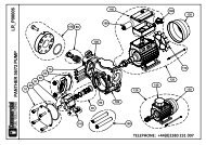
3.3.1 Pump casing (13) – assembly and disassembly<br />
Follow the safety instructions in above section 3.3<br />
Disassembly<br />
- Remove the casing mounting screws (141), washers (142) and nuts (143).<br />
- Carefully remove the casing (13).<br />
Check the casing O-ring (18) and replace with new one if worn or damaged.<br />
Assembly<br />
- When reassembling the casing, make sure that the O-ring sealing surfaces on the casing (13)<br />
and the back casing (12) are clean.<br />
- Put the casing O-ring (18) on the back casing (12).<br />
- Assemble the pump casing (13), insert the casing mounting screws (141), washers (142) and<br />
nuts and tighten alternately.<br />
Fig. 3.3 Assembly drawing for CT pumps<br />
Instruction manual CT centrifugal pumps 12
3. MAINTENANCE<br />
3.3.2 Impeller (90) and back casing (12) – disassembly<br />
Disassemble the pump casing (13) according to chapter 3.3.1<br />
- Remove the impeller mounting screw (191) and the washer (192).<br />
- Remove the impeller (90).<br />
- Carefully remove the rotating seal part with spring (15A).<br />
- Carefully remove the back casing (12). The static part of the mechanical seal (15B) will remain in<br />
the back casing.<br />
3.3.3 Mechanical seal (15) – assembly and disassembly<br />
Follow the disassembly instructions for the pump casing (3.3.1) and impeller and back casing (3.3.2).<br />
Disassembly<br />
- When the impeller (90) has been removed, the rotating part of the seal (15A) remains on the shaft<br />
extension (16). The static part (15B) remains in the back casing.<br />
- Carefully push out the static part of the seal (15B).<br />
- Pull out the rotating part of the seal (15A) from the shaft extension (16).<br />
Check the sealing surfaces and the O-rings. If they are worn or damaged, replace the complete<br />
mechanical seal (15).<br />
Assembly<br />
- Before assembly, wet the O-rings on the seal with soapy water.<br />
- Carefully insert the static part of the seal (15B) in the back casing.<br />
- Fit the back casing (12) onto the back cover (11).<br />
- Check the seal fitting dimensions according to table 3.3.3 to ensure the correct pressure on the<br />
seal. This procedure is important only if you have disassembled the motor/shaft extension. In<br />
order to adjust the dimension ”S”, move the shaft extension (16).<br />
- Carefully slide the rotating part of the seal (15A) onto the shaft extension (16).<br />
- Mount the impeller as described in the next section.<br />
Table 3.3.3<br />
Pump type<br />
S (mm)<br />
CTAA-03 33<br />
CTBB-07 33<br />
CTCC-15 35,5<br />
CTCC-22 35,5<br />
CTCE-22 35,5<br />
CTDD-40 35,5<br />
CTDF-40 35,5<br />
CTDF-55 35,5<br />
CTDG-55 35,5<br />
Changes reserved without notice<br />
Instruction manual CT centrifugal pumps 13
3. MAINTENANCE<br />
3.3.4 Assembly of impeller (90)<br />
- Push the impeller (90) towards the spring of the rotating seal part (15A) and mount the impeller on<br />
the shaft extension (16).<br />
- Make sure that the impeller is locked in its position and tighten the impeller mounting screw (191)<br />
with its washer (192).<br />
3.3.5 Replacement of motor (1)<br />
Follow the instructions for disassembly of the impeller and back casing according to chapter 3.3.2.<br />
- Remove the deflector (17) from the shaft extension (16).<br />
- Loosen the lock screws (161) and remove the shaft extension (16).<br />
- Remove the back cover screws (121) and washers (122).<br />
- Remove the back cover (11).<br />
Check the motor and repair or replace according to the instructions from the motor manufacturer.<br />
Assemble in the reverse order<br />
3.4 Mounting torques and dimensions of screws/nuts<br />
Pos 121, allen screw<br />
Pump model<br />
CT A.. CT B.. CT C.. CT D..<br />
Mounting torque (Nm) 15 15 15 15<br />
Tool size "s" (mm) 5 5 6 6<br />
Thread M6 M6 M8 M8<br />
Pos 141, allen screw<br />
Mounting torque (Nm) 15 15 15 15<br />
Tool size "s" (mm) 5 6 8 6<br />
Thread M6 M8 M10 M8<br />
Pos 143, hexagonal nut<br />
Mounting torque (Nm) 15 15 15 15<br />
Tool size "s" (mm) 10 13 17 13<br />
Thread M6 M8 M10 M8<br />
Pos 161, allen screw<br />
Mounting torque (Nm) 17 17 17 17<br />
Tool size "s" (mm) 3 3 4 4<br />
Thread M6 M6 M8 M8<br />
Pos 191, hexagonal screw<br />
Mounting torque (Nm) 17 17 17 17<br />
Tool size "s" (mm) 17 17 17 17<br />
Thread M10 M10 M10 M10<br />
Changes reserved without notice<br />
Instruction manual CT centrifugal pumps 14
4. SPARE PARTS<br />
4.1 Spare part drawing CT pumps<br />
4.2 Spare part list<br />
Pos Description Pump model / quantity Material<br />
AA-03 BB-07 CC-15 DD-40 DF-55<br />
CC-22 DF-40 DG-55<br />
CE-22<br />
1 Electric motor 1 1 1 1 1<br />
11 Back cover 1 1 1 1 1 AISI 316L<br />
12 Back casing 1 1 1 1 1 AISI 316L<br />
121 Back cover mounting screws 4 4 4 4 4 AISI 316L<br />
122 Back cover mounting washers 4 4 4 4 4 AISI 316L<br />
13 Pump casing 1 1 1 1 1 AISI 316L<br />
141 Casing mounting screws 4 4 4 8 8 AISI 316L<br />
142 Casing mounting washers 4 4 4 8 8 AISI 316L<br />
143 Casing mounting nuts 4 4 4 8 8 AISI 316L<br />
15 Mechanical seal (complete) 1 1 1 1 1 See 4.4<br />
16 Shaft extension 1 1 1 1 1 AISI 316L<br />
161 Lock screw 1 1 2 2 2 AISI 316L<br />
17 Deflector 1 1 1 1 1 Natural rubber<br />
18 Casing O-ring 1 1 1 1 1 Silicon (std)<br />
EPDM<br />
FKM<br />
191 Impeller mounting screw 1 1 1 1 1 AISI 316L<br />
192 Impeller mounting washer 1 1 1 1 1 AISI 316L<br />
90 Impeller 1 1 1 1 1 AISI 316L<br />
Accessories<br />
21 Base plate complete 1 1 1 1 1 AISI 316L<br />
31 Motor cover complete 1 1 1 1 1 AISI 316L<br />
Instruction manual CT centrifugal pumps 15
4. SPARE PARTS<br />
4.3 Stocking recommendation<br />
Normally the CT pump is maintenance free. However, depending on the nature of the liquid and<br />
temperature etc, some parts of the pump are subject to wear and have to replaced. We recommend<br />
having the following parts in stock:<br />
Pos Description Qty<br />
15 Mechanical seal (complete) 1<br />
18 Casing O-ring 1<br />
4.4 Pump code<br />
The model number on the pump tells the pump size and material of the pump<br />
CT centrifugal pump<br />
For motor size (IEC)<br />
A = 71<br />
B = 80<br />
C = 90<br />
D = 100/112<br />
Impeller size<br />
A = 90 mm<br />
B = 98 mm<br />
C = 125 mm<br />
D = 130 mm<br />
E = 135 mm<br />
F = 155 mm<br />
G = 180 mm<br />
Motor options<br />
blank* = 3-phase, 3x380V<br />
IP 55<br />
M = Motor cover in<br />
AISI 304L<br />
P = 1-phase motor<br />
X = Ex-proof motor<br />
CT A A - 1S3D - 03 P 4<br />
Poles on motor<br />
blank* = 2 poles (~2900 rpm)<br />
4 = 4 poles (~1400 rpm)<br />
Pump options<br />
Mechanical seal:<br />
blank* = ceramic/graphite/EPDM<br />
1S = SiC/SiC/FKM<br />
1V = ceramic/graphite/FKM<br />
Casing o-ring:<br />
blank* = silicon<br />
2E = EPDM<br />
2V = FKM<br />
Motor power<br />
03 = 0,37 kW<br />
07 = 0,75 kW<br />
15 = 1,5 kW<br />
22 = 2,2 kW<br />
40 = 4,0 kW<br />
55 = 5,5 kW<br />
Connections:<br />
blank* = BSP external thread<br />
3D = DIN 11851 Threads<br />
3S = SMS threads<br />
* = Standard execution<br />
Changes reserved without notice<br />
Instruction manual CT centrifugal pumps 16
5. DATA<br />
5.1 Performance curves<br />
The performance curves are based on water at 20°C. Speed 2900 rpm.<br />
Contact us for detailed curves.<br />
5.2 Technical data and limits<br />
Limits<br />
Temperature: max 90°C<br />
Viscocity:<br />
max ~200 cSt<br />
Particles:<br />
max diameter 6 mm (bigger if soft)<br />
Max system pressure 10 bar (PN 10)<br />
Max suction pressure 2 bar<br />
Housing and impeller material<br />
AISI 316L electro polished stainless steel<br />
Mechanical seal<br />
Standard:<br />
ceramic/graphite/EPDM<br />
Options:<br />
ceramic/graphite/FKM<br />
SiC/SiC/FKM<br />
Casing o-ring<br />
Standard:<br />
Options:<br />
Motor<br />
Standard:<br />
Options:<br />
Connections<br />
Standard:<br />
Options:<br />
Options<br />
silicon<br />
EPDM<br />
FKM<br />
IP55, 3-phase 220/380 V, 50 Hz, 2900 rpm, IEC frame B3/B14<br />
1-phase motor<br />
Ex-proof motor (contact us for details)<br />
BSP external threads<br />
DIN 11851 or SMS threads<br />
Trolley in stainless steel<br />
Motor cover in stainless steel<br />
Baseplate in stainless steel<br />
Changes reserved without notice<br />
Instruction manual CT centrifugal pumps 17
5. DATA<br />
5.3 Dimensions<br />
Dimensions in mm, where other is not indicated<br />
General dimensions<br />
Model Motor Connections A B C D E F G H I øJ L M<br />
power Ra Ri<br />
(kW)<br />
CTAA-03 0.37 1” ¾ ” 60 359 36 100 71 197 90 112 73 7 112 135<br />
CTBB-07 0.75 1½” 1” 63 393 50 110 80 208 100 125 86 9 125 153<br />
CTCC-15 1.5 1½” 1½” 64 444 66 160 90 228 125 150 103 10 140 170<br />
CTCC-22 2.2 1½” 1½” 64 444 66 160 90 228 125 150 103 10 140 170<br />
CTCE-22 2.2 1½” 1½” 64 444 66 160 90 228 125 150 103 10 140 170<br />
CTDD-40 4 2” 2” 70 493 92 192 100 255 140 172 128 12 160 197<br />
CTDF-40 4 2” 2” 70 493 92 192 100 255 140 172 128 12 160 197<br />
CTDF-55 5.5 2” 2” 70 521 92 192 112 262 140 168 128 12 190 222<br />
CTDG-55 5.5 2” 2” 70 521 92 192 112 262 140 168 128 12 190 222<br />
Optional connections<br />
Model<br />
Optional connections<br />
SMS DIN 11851<br />
Ra Ri Ra Ri<br />
CTAA-03 1” 1” 25 20<br />
CTBB-07 1 1/2” 1” 40 25<br />
CTCC-15 1 1/2” 1 1/2” 40 40<br />
CTCC-22 1 1/2” 1 1/2” 40 40<br />
CTCE-22 1 1/2” 1 1/2” 40 40<br />
CTDD-40 2” 2” 50 50<br />
CTDF-40 2” 2” 50 50<br />
CTDF-55 2” 2” 50 50<br />
CTDG-55 2” 2” 50 50<br />
Changes reserved without notice<br />
Instruction manual CT centrifugal pumps 18
6. WARRANTY & REPAIR<br />
6.1 Returning parts<br />
When returning parts to Tapflo AB please follow this procedure:<br />
- Consult Tapflo AB for shipping instructions.<br />
- Cleanse or neutralize and rinse the part/pump. Make sure the part/pump is completely empty<br />
from liquid.<br />
- Pack the return articles carefully to prevent any damage under transport.<br />
Goods will not be accepted unless the above procedure has been complied with.<br />
6.2 Warranty<br />
Tapflo AB warrants products* of it's own manufacture will be free from defects in raw material and<br />
manufacture under normal use and service for a period of not more than one year. Tapflo's obligation<br />
under this warranty being limited to repair or replacement of its products which shall be returned to<br />
Tapflo AB. Follow the procedures above "returning parts". If a pump or part is received defected,<br />
report to Tapflo AB immediately. Parts returned to our company must have written authorisation from<br />
Tapflo AB. This warranty will not apply to any of our products which shall have been used other than<br />
for their intended use.<br />
* Even when products such as CT centrifugal pumps operate under normal conditions, some parts are<br />
subject to wear and may have to be replaced within one year. Examples of such parts in Tapflo CT pumps<br />
are; mechanical seal, casing o-ring etc. This warranty will not apply to these parts being subject to wear.<br />
Instruction manual CT centrifugal pumps 19
6. WARRANTY & REPAIR<br />
6.3 Warranty form<br />
Company:<br />
Telephone:<br />
Fax:<br />
Address:<br />
Country:<br />
Contact name:<br />
E-mail:<br />
Delivery date:<br />
Pump type:<br />
Pump was installed (date):<br />
Serial No (see name plate):<br />
Description of the fault:<br />
The installation<br />
Liquid:<br />
Temperature (°C): Viscosity (cPs): Spec. grav. (kg/m 3 ): pH-value:<br />
Contents of particles:<br />
%, of max size (mm):<br />
Flow (l/min): Duty (h/day): No of starts per day:<br />
Discharge head (mwc):<br />
Suction head/lift (m):<br />
Other:<br />
Place for sketch of the installation<br />
Instruction manual CT centrifugal pumps 20
DISTRIBUTOR<br />
: Commercial Fuel Solutions Ltd :: City West, Millbrook Road East, Southampton, SO15 1AH<br />
Tel: +44 (0)845 688 9755<br />
Fax: +44 (0)845 688 9744<br />
www.commercialfuelsolutions.co.uk