MC-BOX
PIUSI Cube MC70 Software Manual :: Commercial Fuel Solutions Ltd
PIUSI Cube MC70 Software Manual :: Commercial Fuel Solutions Ltd
Create successful ePaper yourself
Turn your PDF publications into a flip-book with our unique Google optimized e-Paper software.
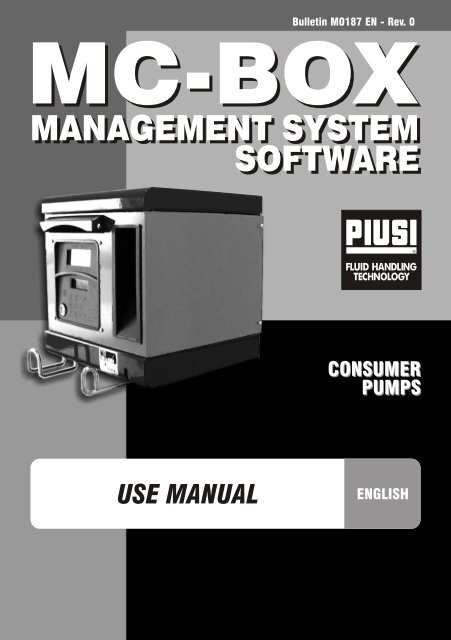
Bulletin M0187 EN - Rev. 0<br />
<strong>MC</strong>-<strong>BOX</strong><br />
MANAGEMENT SYSTEM<br />
SOFTWARE<br />
CONSUMER<br />
PUMPS<br />
USE MANUAL<br />
ENGLISH
EN<br />
A<br />
CONTENTS<br />
1 WHAT IS <strong>MC</strong>-<strong>BOX</strong>? .........................<br />
2 FUNCTIONS OVERVIEW ................<br />
2.1 ACCESS CONTROL ...................<br />
2.2 USERS ........................................<br />
2.3 CONFIGURATING <strong>MC</strong>-<strong>BOX</strong> .......<br />
2.4 MANAGING <strong>MC</strong>-<strong>BOX</strong> .................<br />
2.5 DISPENSING ..............................<br />
2.6 PROCESSING DATA ON PC<br />
(OPTIONAL).................................<br />
3 HOW <strong>MC</strong>-<strong>BOX</strong> WORKS ..................<br />
3.1 OPERATING MODES ..................<br />
3.2 DISPLAYS ...................................<br />
3.3 KEYPAD ......................................<br />
3.4 ELECTRONIC KEYS AND<br />
KEY READER ..............................<br />
4 USING <strong>MC</strong>-<strong>BOX</strong> ...............................<br />
4.1 GENERAL INFORMATION ..........<br />
4.1.1 SOFTWARE FLOW<br />
CHARTS ............................<br />
4.1.2 SOFTWARE OVERVIEW ...<br />
4.2 BOOT ..........................................<br />
4.3 TANK LEVEL ALARM ..................<br />
4.4 ACCESS CONTROL ...................<br />
4.5 SYSTEM CONFIGURATION .......<br />
4.5.1 SETUP<br />
CONFIGURATION .............<br />
4.5.2 CHANGING<br />
CONFIGURATION .............<br />
4.6 SYSTEM MANAGEMENT ...........<br />
4.6.1 REPORT ............................<br />
4<br />
4<br />
4<br />
4<br />
4<br />
5<br />
5<br />
5<br />
6<br />
6<br />
7<br />
7<br />
8<br />
9<br />
9<br />
9<br />
11<br />
12<br />
13<br />
15<br />
15<br />
16<br />
19<br />
19<br />
19<br />
4.6.1.1 REPORT /<br />
TRANSACTION ......<br />
4.6.1.2 REPORT / USERS ..<br />
4.6.1.3 REPORT /<br />
CONFIGURATION ..<br />
4.6.1.4 REPORT /<br />
TOTALS ..................<br />
4.6.2 USERS ................................<br />
4.6.2.1 USERS / ADD .........<br />
4.6.2.2 USERS / DELETE ...<br />
4.6.2.3 USERS / PRINT ......<br />
4.6.2.4 USERS / VIEW ........<br />
4.6.3 SYSTEM .............................<br />
4.6.3.1 SYSTEM / SERIAL<br />
NUMBER ................<br />
4.6.3.2 SYSTEM /<br />
MEMORY ................<br />
4.6.3.3 SYSTEM / DATA /<br />
TIME .......................<br />
4.6.3.4 SYSTEM /<br />
BUZZER .................<br />
4.6.4 CHECK KEY .......................<br />
4.6.5 CALIBRATION ....................<br />
4.6.5.1 CALIBRATION<br />
VIEW .......................<br />
4.6.5.2 CALIBRATION<br />
MODIFY ..................<br />
4.6.6 DATA TRANSFER ...............<br />
4.7 DISPENSING .................................<br />
4.7.1 ALERT MESSAGES ............<br />
4.7.2 OPTIONAL INPUTS ............<br />
4.7.3 DISPENSING ......................<br />
4.7.4 PRESET DISPENSING .......<br />
19<br />
21<br />
21<br />
22<br />
24<br />
24<br />
26<br />
26<br />
26<br />
27<br />
28<br />
28<br />
29<br />
29<br />
30<br />
31<br />
31<br />
31<br />
34<br />
37<br />
37<br />
38<br />
38<br />
39<br />
3
EN<br />
1 WHAT IS <strong>MC</strong>-<strong>BOX</strong>?<br />
<strong>MC</strong> is an electronic system, integrated in <strong>MC</strong>-<strong>BOX</strong> refuelling stations, for controlling<br />
diesel fuel dispensers.<br />
The system provides:<br />
- For the system manager: complete control over all functions, during system<br />
configuration and data collection/processing.<br />
- For users: user-friendly dispensing operations.<br />
This manual refers to the following versions of <strong>MC</strong> <strong>BOX</strong>:<br />
• <strong>MC</strong> <strong>BOX</strong> 230V • <strong>MC</strong> <strong>BOX</strong> 110V • <strong>MC</strong> <strong>BOX</strong> 24V • <strong>MC</strong> <strong>BOX</strong> 12V<br />
2 FUNCTIONS OVERVIEW<br />
2.1 ACCESS CONTROL<br />
<strong>MC</strong> limits access to only to authorized users.<br />
<strong>MC</strong> identifies authorized users in two alternative ways:<br />
- a 4-digit PIN CODE.<br />
- an ELECTRONIC KEY.<br />
2.2 USERS<br />
There are two kinds of users, with access privileges:<br />
- MANAGER. Only ONE manager is allowed for every <strong>MC</strong> system.<br />
The manager is assigned a MASTER PIN CODE and/or a MASTER KEY.<br />
- USERS. Up to 80 o 120, depending on the model of <strong>MC</strong>-<strong>BOX</strong>.<br />
Each user is assigned an individual PIN CODE and/or USER KEY.<br />
WARNING<br />
All <strong>MC</strong> systems are factory-programmed with a MASTER PIN CODE = 1234.<br />
The system manager can change the MASTER PIN CODE. If the manager loses the<br />
MASTER PIN CODE, he will not be allowed to access the functions reserved for the<br />
manager. In this case the manager should contact our CUSTOMER SERVICE and<br />
request the "SUPER MASTER CODE," which will make it possible to retrieve the lost<br />
MASTER PIN CODE.<br />
SUPER MASTER CODES are different for each <strong>MC</strong> system and cannot be changed;<br />
they should therefore remain strictly confidential.<br />
2.3 CONFIGURATING <strong>MC</strong>-<strong>BOX</strong><br />
4<br />
Only the MANAGER can access configuration functions, through which <strong>MC</strong>-<strong>BOX</strong> can be<br />
customized and adapted to meet specific requirements.<br />
The main configuration operations are:<br />
- Assigning a name to the station.<br />
- Requesting optional inputs (vehicle plate number and/or odometer reading).<br />
- Determining time out at start or at end of dispensing.<br />
- Using a remote printer.<br />
- Deciding what unit of measurement to use for dispensing.<br />
- Connecting the system to a PC for data collection/processing.<br />
- Changing the MASTER CODE.
EN<br />
2.4 MANAGING <strong>MC</strong>-<strong>BOX</strong><br />
Only the MANAGER can access management functions, through which he can control all<br />
operations performed with the <strong>MC</strong>-<strong>BOX</strong> station.<br />
The main management functions include:<br />
- Creating/deleting users.<br />
- Processing system data (memory / date / time).<br />
- Calibrating the on-board flow meter.<br />
- Transferring data from <strong>MC</strong>-<strong>BOX</strong> to a PC by the MASTER KEY.<br />
OPTIONAL management functions include:<br />
- Printing different kinds of reports on a remote printer.<br />
- Printing a user list on a remote printer.<br />
- Printing system configuration details on a remote printer.<br />
2.5 DISPENSING<br />
Dispensing functions are accessible only by USERS, who can be requested to:<br />
- enter the vehicle's plate number or any identifying number (REG. NUMBER);<br />
- enter the vehicle's odometer reading (ODOMETER);<br />
- pre-select the desired amount of fuel (PRESET).<br />
2.6 PROCESSING DATA ON PC (OPTIONAL)<br />
Data regarding the dispensing operations, collected and stored in <strong>MC</strong>'s non-volatile<br />
memory, can be transferred to a PC for further processing and permanent storage.<br />
To process the data the PC must have installed the SELF <strong>MC</strong>-<strong>BOX</strong> MANAGEMENT,<br />
provided separately as an optional feature for <strong>MC</strong>-<strong>BOX</strong>.<br />
There are two ways to transfer data from <strong>MC</strong>-<strong>BOX</strong> to a PC:<br />
- Through an RS 485 cable connection. In this case you should install an RS 232/485<br />
CONVERTER on the RS 232 serial port of the PC. The converter is supplied separately.<br />
- Through the MASTER KEY. In this case you should install a KEY READER on the RS 232<br />
serial port of the PC. The key reader is supplied separately.<br />
5
EN<br />
3 HOW <strong>MC</strong>-<strong>BOX</strong> WORKS<br />
3.1 OPERATING MODES<br />
<strong>MC</strong> enters the various OPERATING MODES automatically, depending on what events<br />
take place.<br />
• SYSTEM Mode<br />
In this operating mode <strong>MC</strong> performs all the functions related to access control and<br />
system management. <strong>MC</strong> automatically enters SYSTEM mode any time a user<br />
presses a button (except buttons used in LEVEL mode), or applies an electronic key<br />
or finishes dispensing.<br />
When it is in SYSTEM mode, <strong>MC</strong> requests and accepts INPUT through the keypad and<br />
provides OUTPUT through displays or a printer.<br />
• DISPENSING Mode<br />
This is the operating mode in which fuel is dispensed.<br />
The system exits dispensing mode when a user presses STOP, when a preset quantity<br />
of fuel has been dispensed or when a certain period of time has elapsed without<br />
dispensing.<br />
• MANUAL Mode<br />
In this mode a user can dispense fuel BYPASSING <strong>MC</strong> FUNCTIONS.<br />
This is a special operating mode - it should be used only under exceptional circumstances,<br />
such as when management necessities require fuel to be dispensed without the<br />
operation being recorded and/or when you want to simplify setup or maintenance<br />
operations that requite the pump to be started and stopped repeatedly.<br />
WARNING<br />
When it is in MANUAL mode, <strong>MC</strong> does not record any dispensing operations.<br />
To enter MANUAL mode, proceed as follows:<br />
- Unscrew and remove the cover panel from the <strong>MC</strong> Box to access the circuit boards.<br />
- Move the jumper from the position in which you find it (by default it bridges the two<br />
upper contacts in AUTO mode) to the lower position, i.e. the jumper should bridge the<br />
two lower contacts.<br />
In MANUAL mode:<br />
• The LCDs will continue to show what was being displayed when switching from AUTO<br />
to MAN.<br />
• No PIN CODE or KEY is necessary to start the pump; the pump starts as soon as the<br />
nozzle is lifted and stops when it is put back in its place.<br />
• <strong>MC</strong>-<strong>BOX</strong> does not show the amount of fuel dispensed in any way.<br />
6
EN<br />
3.2 DISPLAYS<br />
Two backlit displays provide different information, depending on which OPERATING<br />
MODE <strong>MC</strong> is currently in.<br />
NUMERIC DISPLAY<br />
(1 line containing 4 numeric characters)<br />
- In LEVEL mode<br />
shows current time<br />
- In SYSTEM mode<br />
shows current time<br />
- In DISPENSING mode<br />
shows quantity dispensed<br />
ALPHANUMERIC DISPLAY<br />
(2 lines containing 16 alphanumeric<br />
characters)<br />
- In LEVEL mode<br />
shows prompt message<br />
- In SYSTEM mode<br />
shows prompt message and/or<br />
data entered<br />
- In DISPENSING mode<br />
shows unit of measurement and<br />
user data<br />
NUMERIC<br />
DISPLAY<br />
ALPHANUMERIC<br />
DISPLAY<br />
3.3 KEYPAD<br />
Input is provided through a membrane keypad equipped with:<br />
• 10 alphanumeric buttons<br />
• The following "special" buttons:<br />
STOP<br />
#<br />
CANCEL<br />
STOP<br />
NUMBER<br />
CANCEL<br />
stops the dispenser pump<br />
used in combination with other buttons<br />
for special functions<br />
cancels data or returns to previous stage<br />
ENTER<br />
ENTER<br />
confirms selection or data entered<br />
< ><br />
< ><br />
FS / FG<br />
FD / FS<br />
shifts through menu functions<br />
selects options proposed (flashing)<br />
7
EN<br />
3.4 ELECTRONIC KEYS AND KEY READER<br />
<strong>MC</strong> controls access to the system through two kinds of<br />
ELECTRONIC KEYS.<br />
The MASTER KEY is assigned to the system manager<br />
and can also be used for transferring data to the PC - it is<br />
supplied with a RED key holder.<br />
Every user is assigned a USER KEY by the plant manager<br />
than can be used only for refuelling at the pump. There are<br />
two kinds of USER KEYS:<br />
- a version with a GREEN KEY HOLDER having a four-digit<br />
code (KEY CODE) on the key-grip which is needed to<br />
identify the key at the time of user configuration;<br />
- a version with a YELLOW KEY HOLDER without the<br />
four-digit code on the key-grip.<br />
This version has an internal identification code that is<br />
automatically recognized when the key is used.<br />
ELECTRONIC KEYS are used by pressing them to the<br />
KEY READER located on the <strong>MC</strong>'s front panel.<br />
The stations to be used with USER KEYS with YELLOW key holder indicate the software<br />
release of the station in the second line of the alphanumeric display (ex. ver. 3.0).<br />
This message is displayed only when the station is waiting for pin code entry or key touch.<br />
It is never displayed in the menus or during dispensing.<br />
8
EN<br />
4 USING <strong>MC</strong>-<strong>BOX</strong><br />
4.1 GENERAL INFORMATION<br />
To use <strong>MC</strong> and carry put the appropriate FUNCTIONS, operators must know the<br />
SOFTWARE governing the system.<br />
WARNING<br />
The system MANAGER should have an IN-DEPTH understanding of the software,<br />
since he is likely to use every function at one time or other; the MANAGER should<br />
therefore read and understand every part of the present manual.<br />
USERS only need to know what is necessary for dispensing.<br />
4.1.1 SOFTWARE FLOW CHARTS<br />
All the FUNCTIONS supported by the FM SOFTWARE are described in detail below and<br />
illustrated through FLOWCHARTS that show the information displayed on the LCDs in<br />
the different stages.<br />
The indications displayed on the LCDs (more often on the alphanumeric display only)<br />
are connected by arrows drawn with a continuous line, next to which the functions of the<br />
respective BUTTON are shown.<br />
When a button is pressed the display passes from one indication to the one immediately<br />
following it, connected to the first one by an arrow.<br />
In certain occasions passing from one step to the following does not depend on pressing<br />
a button but occurs automatically at the end of activities lasting an unspecified period<br />
(e.g.: printing a report); in this case the display will show a dotted line and the image<br />
of a clock.<br />
USING THE BUTTONS<br />
SHORT PRESS<br />
(Press button briefly and release immediately)<br />
PRESSING TWO BUTTONS IN COMBINATION<br />
(Press first button and hold down while<br />
briefly pressing second button, then release)<br />
APPLYING A KEY<br />
(Press key to key reader)<br />
9
EN<br />
LIQUID CRYSTAL DISPLAY (GENERAL)<br />
MAIN INDICATIONS ON LCD<br />
FLASHING MESSAGES<br />
ALTERNATE FLASHING MESSAGES<br />
FLOW CHART<br />
10
EN<br />
WARNING<br />
CANC BUTTON<br />
For simplicity, in some FLOW CHARTS the CANC button is not shown, although it<br />
can be used at almost any stage.<br />
Pressing the CANC button has one of the following effects:<br />
- return to previous screen, or<br />
- cancel numerical data entered.<br />
TIME OUT<br />
During any function, if no action is taken (pressing a button, applying a key,<br />
dispensing fuel) in a fixed period of time (TIME OUT), the system will automatically<br />
exit the function. This ensures that <strong>MC</strong> does not remain in an input-expecting<br />
mode and prevents access by unauthorized users.<br />
The TIME OUT function is not shown in the FLOW CHARTS.<br />
4.1.2 SOFTWARE OVERVIEW<br />
All the functions provided by <strong>MC</strong>-<strong>BOX</strong> SOFTWARE are grouped in SECTIONS. Each<br />
SECTION contains functions that are consistent with each other.<br />
SECTIONS can be automatically accessed, freely accessed or access-protected by a<br />
PIN CODE.<br />
The SOFTWARE OVERVIEW describes the available sections and gives a brief<br />
description of each function contained.<br />
The SECTIONS are:<br />
BOOT<br />
<strong>MC</strong> performs a self-diagnosis on the LCDs and displays the MODEL and SERIAL NUMBER.<br />
Enter: - automatically, at start-up.<br />
Exit: - automatically, when completed.<br />
SYSTEM MANAGEMENT<br />
Management operations (reports, enabling users, calibrating, transferring data to a to PC).<br />
Enter: - from ACCESS CONTROL, after entering a key or a SYSTEM code number.<br />
Exit: - when function completed or at time out.<br />
SYSTEM CONFIGURATION<br />
Customizing <strong>MC</strong> for specific plant requirements.<br />
Enter: - from SYSTEM in SYSTEM MANAGEMENT menu.<br />
Exit: - when function completed or at time out.<br />
DISPENSING<br />
Fuel dispensing operations.<br />
Enter: - from ACCESS CONTROL, after entering a key or a USER code number.<br />
Exit: - when function completed or at time out.<br />
Some carry out their functions without user input (BOOT, ACCESS CONTROL).<br />
Others require an input to perform a function (SYSTEM CONFIGURATION,<br />
DISPENSING). Input must be made in sequence, and <strong>MC</strong> prompts the user to enter the<br />
requested information.<br />
After providing the requested input the section will automatically be exited.<br />
Other sections (SYSTEM MANAGEMENT) are more complex and appear in form of<br />
MENU. The user (in this case only the MANAGER) accesses the menu and chooses the<br />
desired function, which can itself be organized as a lower-level MENU (SUBMENU).<br />
Sections are described in detail below.<br />
11
EN<br />
4.2 BOOT<br />
The BOOT section is fundamentally a TEST section, in which <strong>MC</strong> automatically carries<br />
out a number of checks.<br />
The BOOT section is performed only in one of the following situations:<br />
• When <strong>MC</strong> is powered up (by a master switch that the installer should place between<br />
the power supply and <strong>MC</strong>-<strong>BOX</strong>).<br />
• When, without cutting and giving power, the AUTO/MAN jumper is switched from MAN<br />
to AUTO (see Sect. 3.1).<br />
In the BOOT section the operator can:<br />
- make sure the displays are working properly (they light up completely for a few seconds)<br />
- check the MODEL<br />
- check the SERIAL NUMBER.<br />
WARNING<br />
The SERIAL NUMBER shown during BOOT is the S/N of the CPU mounted on <strong>MC</strong>.<br />
The S/N is required to access the data collected by <strong>MC</strong> in case you lose the<br />
MASTER KEY and the MASTER PIN CODE. If this happens, you should note down<br />
the station's S/N and contact CUSTOMER SERVICE.<br />
12
EN<br />
4.3 TANK LEVEL ALARM<br />
<strong>MC</strong>-<strong>BOX</strong> is designed to be connected to an optional external level alarm equipped with<br />
a normally-open dry contact. The contact closes when an alarm signal arrives.<br />
The connection must be made directly to <strong>MC</strong>'s junction box through the tank cap, which<br />
should be replaced by a PG7-type core hitch.<br />
The way <strong>MC</strong> reacts when reaching alarm level depends on its configuration.<br />
• CONFIGURATION 1<br />
LEVEL INPUT = NO / LEVEL OUTPUT = ALARM or LEVEL OUTPUT = PUMP CUTOUT<br />
<strong>MC</strong> does not react to inputs from the level sensor and takes no specific action.<br />
• CONFIGURATION 2<br />
LEVEL INPUT = YES / LEVEL OUTPUT = ALARM<br />
<strong>MC</strong> prints a "WARNING LOW LEVEL" message on the remote printer, if enabled, after<br />
the current dispensing is finished.<br />
Dispensing remains possible.<br />
No message appears on the LCD.<br />
• CONFIGURATION 3<br />
LEVEL INPUT = YES / LEVEL OUTPUT = BLOCK<br />
<strong>MC</strong> disables any further dispensing.<br />
The LCD shows “DISPENSING IMPOSSIBLE / MINIMUM LEVEL”.<br />
POWER IN<br />
230V/110V<br />
GREEN/YELLOW<br />
BROWN<br />
BLUE<br />
BLACK<br />
GREEN/YELLOW<br />
1<br />
GREY or BLACK<br />
<strong>MC</strong>-<strong>BOX</strong> 230V - 110V<br />
TO K600<br />
PULSER<br />
BROWN<br />
WHITE<br />
GREEN<br />
BLUE<br />
2<br />
TO MOTOR<br />
TO NOZZLE<br />
CONTACT<br />
BROWN<br />
GREEN/YELLOW<br />
BLUE<br />
BLUE<br />
GREEN/YELLOW<br />
BROWN<br />
RS485+<br />
RS485, OUT TO<br />
PC/PRINTER<br />
(OPTIONAL)<br />
RED PINK<br />
GREY YELLOW<br />
3<br />
BROWN<br />
WHITE<br />
BLUE<br />
BROWN<br />
RS485 -<br />
Max Current Motor<br />
Imax = 6A<br />
TO LEVEL<br />
PROBE’S<br />
CONTACT<br />
(OPTIONAL)<br />
RED<br />
PINK<br />
YELLOW<br />
GREY<br />
13
EN<br />
ELECTRICAL DIAGRAM VERSION <strong>MC</strong> <strong>BOX</strong> 12V<br />
ELECTRICAL DIAGRAM VERSION <strong>MC</strong> <strong>BOX</strong> 24V<br />
BROWN<br />
WHITE<br />
RED<br />
PINK<br />
GREY<br />
YELLOW<br />
BLUE<br />
YELLOW<br />
RED<br />
BLUE<br />
BLACK BROWN<br />
IF YOU WANT TO USE<br />
THE NOZZLE CONTACT,<br />
REMOVE THE JUMPER<br />
WHITE<br />
BROWN<br />
RED<br />
PINK<br />
RS-485+<br />
RS-485 -<br />
BLACK<br />
RED<br />
VERSION 12V: TO POWER 12V<br />
BLUE<br />
YELLOW<br />
VERSION 24V: TO POWER 24V VERSION 12V: TO RELAY 12V<br />
VERSION 24V: TO RELAY 24V<br />
TO K 600 RS485<br />
PULSER OU T<br />
TO<br />
PC/PRINTER<br />
(OPTIONAL)<br />
LEVEL<br />
CONTACT<br />
NOZZLE<br />
CONTACT<br />
IN BATT<br />
-<br />
+<br />
YELLOW<br />
BLUE<br />
RED<br />
BLACK<br />
85<br />
86<br />
87<br />
30<br />
R-C<br />
FILTER<br />
+ -<br />
Key ON-OFF<br />
Max Current Motor Imax = 60A<br />
MOTOR<br />
12V<br />
+ -<br />
BATTERY<br />
12V<br />
IF YOU WANT TURN-ON AND<br />
TURN-OFF THE DEVICE WITH A KEY,<br />
SUBSTITUTE THIS JUMPER WITH<br />
THE KEY-SWITCH<br />
VERSION 12V: MOTOR 12V<br />
VERSION 24V: MOTOR 24V<br />
VERSION 12V: BATTERY 12V<br />
VERSION 24V: BATTERY 24V<br />
14
EN<br />
4.4 ACCESS CONTROL<br />
The system enters ACCESS CONTROL when start-up booting has been completed or<br />
when one of the following events take place:<br />
Pressing a NUMERIC button, as when entering a PIN CODE. <strong>MC</strong> checks whether the<br />
PIN CODE is enabled and whether it belongs to a USER or the MANAGER.<br />
If the system fails to recognize the code number, an "UNKNOWN CODE" alert message<br />
is displayed.<br />
If the number is recognized, the system does as follows, depending on the type of code<br />
number:<br />
- if USER PIN CODE<br />
the system enters DISPENSING mode<br />
- if MASTER PIN CODE<br />
the system activates the REPORT function in the SYSTEM MANAGEMENT menu<br />
- Introducing a KEY in the KEY READER.<br />
<strong>MC</strong> checks whether the KEY is enabled and whether it is a USER KEY (green)<br />
or MASTER key (red).<br />
If the system fails to recognize the key, an "UNKNOWN USER KEY" message is<br />
displayed.<br />
If the key is recognized, the system does as follows, depending on the type of key:<br />
- if USER KEY<br />
the system enters DISPENSING mode<br />
- if MASTER KEY<br />
the system activates the DATA TRANSFER function in the MASTER MANAGEMENT menu<br />
WARNING<br />
Since the MASTER KEY is chiefly used for transferring data from <strong>MC</strong>-<strong>BOX</strong> to a PC<br />
(if the optional software is installed), when the system recognizes the MASTER KEY<br />
it automatically opens the DATA TRANSFER menu.<br />
Once in this menu, the user can access any other function available in the menu.<br />
Therefore, the MANAGER PIN CODE and the MASTER KEY are two ALTERNATIVE<br />
ways of accessing SYSTEM MANAGEMENT, both reserved exclusively for the plant<br />
MANAGER.<br />
4.5 SYSTEM CONFIGURATION<br />
In SYSTEM CONFIGURATION the system can be customized and adapted to the<br />
specific requirements of the fuelling station.<br />
Only the MANAGER (or the installer) can access SYSTEM CONFIGURATION, using<br />
either the MASTER PIN CODE or the MASTER KEY.<br />
To access the CONFIGURATION section:<br />
- enter SYSTEM MANAGEMENT<br />
- shift through the menu until you reach SYSTEM<br />
- press the “#” and “1” buttons in combination.<br />
15
EN<br />
4.5.1 SETUP CONFIGURATION<br />
The system must be configured at first installation. Before configuring the system, the<br />
installer and the manager should decide which among all available options are more<br />
suitable for the fuelling plant.<br />
Configuration requires a number of OPERATIONS (selections to make or data to enter)<br />
that must be performed in sequence.<br />
For each operation the system proposes a DEFAULT value that can be edited or accepted<br />
by pressing ENTER (which leads to the next operation).<br />
Each operation is described below in full detail.<br />
The title of the sections is the same as the indications shown on the LCD in the respective<br />
operation.<br />
UNIT NAME<br />
(Name of unit)<br />
The name assigned to the station by the system manager. It can be left blank.<br />
DEFAULT:<br />
none<br />
Options:<br />
an ALPHANUMERICAL string of max 16 characters<br />
REGISTRATION NUMBER<br />
(Vehicle plate number)<br />
Determines whether the user is required to enter a name (or number) identifying the<br />
vehicle.<br />
If this option is enabled, the user must enter the required information before being<br />
allowed to refuel (the system accepts any value).<br />
DEFAULT:<br />
DISABLED<br />
Options: DISABLED (name/number not required)<br />
ENABLED (name/number required)<br />
ODOMETER<br />
(Odometer reading)<br />
Determines whether the user is required to enter the odometer reading of the vehicle.<br />
If this option is enabled, the user must enter the required information before being<br />
allowed to refuel (the system accepts any value).<br />
DEFAULT:<br />
DISABLED<br />
Options: DISABLED (information not required)<br />
ENABLED (information required)<br />
START TIME OUT (Period before starting dispensing)<br />
Determines the maximum period within which the user must start dispensing fuel from the<br />
moment the system enables the pump. If the fixed period elapses before dispensing<br />
begins, <strong>MC</strong> disables the pump and the user is required to identify himself again (using<br />
a code number or a key).<br />
DEFAULT:<br />
60 seconds<br />
Range:<br />
001 ÷ 999 seconds<br />
FILLING TIME OUT (Time allowed for interruptions to dispensing)<br />
Determines how long a dispensing operation can be interrupted.<br />
Once started, dispensing cay be temporarily interrupted by the user or by the automatic<br />
nozzle. If the suspension (the pump remains on but the meter is still) lasts longer than<br />
the fixed period of time, the pump is disabled and stopped.<br />
To resume dispensing the user is required to identify himself again (using a code or a key).<br />
When the nozzle is put back in its place, even if the fixed period of time has not elapsed,<br />
dispensing is considered completed (and the pump disabled).<br />
DEFAULT:<br />
120 seconds<br />
Range:<br />
001 ÷ 999 seconds<br />
REMOTE PRINTER (Remote printer)<br />
Determines whether <strong>MC</strong>-<strong>BOX</strong> is to be connected, by an (optional) RS 485 serial line, to<br />
a remote printer (e.g. installed inside an office, that can be at a distance of several hundred<br />
metres) to automatically print one-line reports for each dispensing (logging) or reports<br />
requested by the manager.<br />
16
EN<br />
WARNING<br />
The printer must be equipped, alternatively, with:<br />
- RS 485 serial port<br />
- RS 232 serial port + RS 232/485 converter (supplied on request)<br />
- Centronics parallel port + RS 232/485 converter + RS 232/Centronics converter<br />
(supplied on request)<br />
DEFAULT:<br />
Options:<br />
NO<br />
YES (printer connected)<br />
NO (printer not connected))<br />
REMOTE SERIAL PRINTER SETTINGS (optional):<br />
Protocol: 8 - N - 1<br />
BAUD RATE: 2400<br />
Word Length: 8 bit<br />
Parity:<br />
None<br />
Bit Stop: 1<br />
If YES (printer connected) is selected, the following options will be proposed:<br />
REMOTE PRINTER / TYPE<br />
(Type of remote printer)<br />
Determines whether the remote printer should be a:<br />
- 80-column printer (standard office printer)<br />
- 40-column printer (roll-paper printer for tickets)<br />
DEFAULT: 80 COLUMNS<br />
Options: 80 COLUMNS (80 column printer)<br />
40 COLUMNS (40 column printer)<br />
REMOTE PRINTER / PRINT OUT (Type of printouts on remote printer)<br />
Determines what kind of printouts should be produced by the remote printer:<br />
- tickets (reproduction of a hypothetical receipt printed by the remote printer)<br />
- automatic one-line reports for each dispensing ("logging").<br />
DEFAULT: LOGGING<br />
Options: LOGGING<br />
TICKET<br />
REMOTE PRINTER / AUTO CR-LF (Automatic line jumping)<br />
This function customizes the commands sent by <strong>MC</strong>-<strong>BOX</strong> to the printer to meet printer<br />
settings, which may require special "line feed" instructions in order to work properly.<br />
WARNING<br />
For the first printouts you should leave the default option on; if the printer does not<br />
print the report lines correctly, enter configuration mode and change the option.<br />
DEFAULT:<br />
Options:<br />
NO<br />
NO (line feed disabled)<br />
YES (line feed enabled)<br />
REMOTE PRINTER / LINE DELAY (Printing delay)<br />
If the printer's buffer is not large enough to handle the printing spool, use this function<br />
to change the delay by which the data is sent to the printer, so to facilitate printing<br />
without losing data.<br />
WARNING<br />
For the first printouts you should leave the default option on; if the printer fails to<br />
receive all the data sent to it, enter configuration mode and change the option.<br />
DEFAULT:<br />
100 x 10 ms<br />
Range:<br />
100-999 x 10 ms<br />
17
EN<br />
PC CONNECTED (Connected to PC - only with optional software)<br />
Determines whether <strong>MC</strong>-<strong>BOX</strong> is to be connected, by an RS 485 serial line, to a PC running<br />
the (optional) <strong>MC</strong>-<strong>BOX</strong> MANAGEMENT software for collecting and processing the data<br />
on dispensing operations (see manual no. M00105).<br />
MEASUREMENT UNIT (Unit of measurement)<br />
Determines the unit of measurement used by the system.<br />
DEFAULT: LITRES<br />
Options: LITRES<br />
US GALLONS)<br />
DECIMAL DIGIT (Number of decimals)<br />
Determines how many decimals should be shown when displaying the amount of fuel<br />
dispensed. If 2 decimals are selected, whenever more that 99.99 units of fuel are<br />
dispensed the system will automatically revert to displaying a single decimal.<br />
DEFAULT: 1<br />
Options: 1-2<br />
LOW LEVEL INPUT = YES / NO<br />
This function defines the control of the optional level contact (see sect. 4.3).<br />
With “YES”, the input level is controlled; with “NO”, the input level is not controlled.<br />
LOW LEVEL INPUT = ALARM / PUMP CUT OUT<br />
This option is visible only if the Low Level Input is set to “YES” (see also sect. 4.3).<br />
This selection defines the reply action of the electronics when the level alarm contact<br />
closes. If alarm is chosen, a printout on any remote printer is possible. If “PUMP CUT OUT”<br />
is set, <strong>MC</strong> turns off the pump and fuel dispensing is no longer enabled.<br />
KEY READER<br />
(Electronic key reader)<br />
Enables/disables the electronic key reader located on <strong>MC</strong>'s front panel.<br />
DEFAULT: YES<br />
Options: YES (Reader enabled)<br />
NO (Reader disabled)<br />
MASTER CODE (Manager's code)<br />
Changes the MASTER CODE, which is factory-programmed as "1234". When you open the<br />
function the system displays the current code:<br />
- press “ENTER” to confirm and go to the next step<br />
- press any numeric button to enter a new code.<br />
WARNING<br />
The new code must be a 4-digit number. Enter the new code and press ENTER; <strong>MC</strong><br />
will display both the PREVIOUS code (OLD PIN) and the NEW code (NEW PIN):<br />
- press “ENTER” to confirm the new master code<br />
- press “CANCEL” to cancel the changes and confirm the PREVIOUS code.<br />
MASTER KEY<br />
(Replacing manager's key)<br />
This function enables a new MASTER KEY in replacement of the previous one.<br />
When <strong>MC</strong> displays this message, you can:<br />
- exit SYSTEM CONFIGURATION by pressing "CANCEL"; the existing MASTER KEY<br />
remains enabled;<br />
- apply a new key to the key reader; the key will be enabled as the new MASTER KEY<br />
in replacement of the old one.<br />
WARNING<br />
Only one key at a time can be enabled as the MASTER KEY on any given <strong>MC</strong>-<strong>BOX</strong><br />
station. A same key, however, can be enabled as the MASTER KEY on different<br />
<strong>MC</strong>-<strong>BOX</strong> stations.<br />
18
EN<br />
4.5.2 CHANGING CONFIGURATION<br />
If at any time you want to change a option chosen during the initial configuration,<br />
proceed as follows:<br />
- enter CONFIGURATION mode;<br />
- press “ENTER” to confirm all the options you DO NOT want to change, until you reach<br />
the option you want to edit;<br />
- go through all remaining functions by pressing “ENTER”, until you reach the last one<br />
(NEW MASTER KEY);<br />
- exit CONFIGURATION mode (unless you want to change the MASTER KEY) by<br />
pressing “CANCEL”.<br />
4.6 SYSTEM MANAGEMENT<br />
The SYSTEM MANAGEMENT section is used by the Manager to handle day-to-day <strong>MC</strong><br />
operations.<br />
The section is organized in menus and submenus to facilitate access to the various<br />
functions. The main menu contains six functions, described below.<br />
4.6.1 REPORT<br />
Makes three different kinds of printouts on an (optional) remote printer, as described in<br />
the following FLOW CHART.<br />
4.6.1.1 REPORT / TRANSACTION<br />
Prints all the dispensing operations (TRANSACTIONS) contained in <strong>MC</strong>'s memory.<br />
WARNING<br />
There are two ways to transfer data from <strong>MC</strong>-<strong>BOX</strong>’s memory to a PC running the<br />
optional data-processing software, i.e. through a serial connection or through the<br />
MASTER KEY. Only transactions that have not yet been transferred can be printed,<br />
because when the data is transferred to a PC it is automatically cancelled from the<br />
station's memory.<br />
Data printouts can be:<br />
• complete, i.e. all transactions stored in the<br />
memory (select ALL DATE + ALL USERS);<br />
• limited to a period of time between two<br />
specified dates (select PERIOD);<br />
• limited to a single day (select PERIOD and<br />
enter the date twice);<br />
• limited to a single user (select SINGLE USER)<br />
identified by his USER NUMBER (a number<br />
from 1 to 50 progressively assigned to each<br />
user).<br />
The above limitations can be all applied<br />
simultaneously, for example when you want to<br />
print all the transactions made by a single user<br />
during a specific period of time.<br />
19
EN<br />
20
EN<br />
4.6.1.2 REPORT / USERS<br />
Prints a list of all enabled users.<br />
There are two kinds of lists:<br />
PRINT CODE > YES<br />
Prints a list of users, including a column showing every user's PIN CODE.<br />
PRINT CODE > NO<br />
Prints a list of users without showing the PIN CODES.<br />
WARNING<br />
Printouts containing user PIN CODES should remain confidential, to avoid<br />
revealing users' secret code numbers.<br />
For each user, the printout shows:<br />
- Progressive number assigned to user (USER NUMBER)<br />
- Name of user (USER NAME)<br />
- User's secret code number (PIN CODE)<br />
- Electronic key assigned to user (USER KEY)<br />
If a user is assigned an electronic key only, the USER KEY column will contain an<br />
asterisk (*) and the PIN CODE column will show “0000”.<br />
If a user is assigned a PIN CODE only, it will be a 4-digit number different from “0000” and<br />
no asterisk well appear in the USER KEY column.<br />
PRINT CODE - YES<br />
PRINT CODE - NO<br />
4.6.1.3 REPORT / CONFIGURATION<br />
Prints a list of all selections made in system<br />
configuration, as described below:<br />
For details on the single functions please see<br />
Sect. 4.6.1.<br />
21
EN<br />
4.6.1.4 REPORT / TOTALS<br />
Prints the GENERAL TOTAL, Period Totals (TOTAL FROM XX/XX/XX) and User Totals.<br />
General Total (cannot be reset). Total amount of fuel dispensed from first installation<br />
of <strong>MC</strong>-<strong>BOX</strong> system. This value cannot be changed by the manager in any way.<br />
Period Total (can be reset by manager). Total amount dispensed since last resetting.<br />
This value is the sum of all Users Totals.<br />
User Total (can be reset by manager). Total amount dispensed to a specific user<br />
since last resetting of Period Total.<br />
Single User Totals cannot be reset.<br />
All User Totals are simultaneously reset every time the Period Total is reset.<br />
Totals can be displayed, printed and reset. This is done by the following submenus:<br />
* TOTALS VIEW? Displays the different totals on the LCD<br />
(General Total, Period Total, User Total);<br />
* TOTALS PRINT? Prints the different totals<br />
(General Total, Period Total, User Total);<br />
* TOTALS RESET PERIOD? Resets the Period Total and consequently<br />
all User Totals.<br />
GENERAL TOTAL<br />
PERIOD TOTAL<br />
LAST RESETTING<br />
DATE<br />
TOTALS PRINT ONLY GENERAL<br />
TOTALS PRINT ALL<br />
22<br />
TOTALS PRINT SINGLE USER
EN<br />
23
EN<br />
4.6.2 USERS<br />
This function is for managing all users enabled on <strong>MC</strong>-<strong>BOX</strong>, through four separate<br />
functions contained in a submenu.<br />
WARNING<br />
If no user is enabled, the only function available is the creation of new users<br />
(USER/ADD Sect. 4.6.2.1).<br />
4.6.2.1 USERS / ADD<br />
Creates (adds) and enables a new user, as described in the flow chart below:<br />
NOTE:<br />
WHEN CREATING THE FIRST USER ONLY THE “USER ADD?”<br />
MENU WILL APPEAR ON THE LCD.<br />
ONCE THE USER HAS BEEN CREATED, ALL OTHER MENUS<br />
DESCRIBED IN THIS FLOW CHART WILL BECOME<br />
AVAILABLE.<br />
24
EN<br />
To create a new user follow the steps listed below, in sequence.<br />
USER NAME<br />
Name of user; this is an alphanumeric field containing from 1 to 10 characters.<br />
This field must be filled.<br />
USER PIN<br />
Secret individual code number assigned to each user.<br />
The options are USER PIN > YES / NO.<br />
If the option USER PIN > NO is selected, the user is not assigned a secret code but only<br />
an electronic key, and the system request the key to be applied to the reader<br />
(see below).<br />
If the option USER PIN > YES is selected, the user's secret individual code (a numeric field<br />
containing from 1 to 4 characters) must be entered.<br />
WARNING<br />
At this stage of assigning a user PIN you always have to enter 4 digits. For example,<br />
if you want to assign the number “4” as a user's PIN number, you must enter “0004”.<br />
When refuelling, however, the user only needs to enter “4”. If the user enters a<br />
USER PIN assigned to another user, <strong>MC</strong> will not accept it and will ask for<br />
another code.<br />
ELECTRONIC KEY<br />
The options are ELECTRONIC KEY > YES / NO.<br />
If the option ELECTRONIC KEY > YES is selected, the system will ask you to press the<br />
key to the key reader, displaying the message TOUCH USER KEY, in order to assign that<br />
specific key to the user. The system will exit this stage only when a key is pressed to the<br />
reader and pass to the entry stage of the 4-figure code applied on the key.<br />
If the key has already been assigned to a different user enabled on the same station,<br />
the system will not accept the key and display the message “WARNING KEY ALREADY<br />
ASSIGNED”.<br />
WARNING<br />
Only USER KEYS can be assigned to users.<br />
The system will not assign a MASTER KEY to a user.<br />
KEY CODE<br />
The KEY CODE is the 4-figure code applied on the handle of the USER key enabling the<br />
User Key to be identified by the station. This code is used only during the user's<br />
configuration; the final user does not need it in daily use.<br />
If the key code is lost or damaged, the user key cannot be configured again but its daily use<br />
is possible if previously configured.<br />
WARNING<br />
The key code is required only on models which are provided with Green User Keys.<br />
No code is required on models which are provided with Yellow User Keys.<br />
USER NUMBER<br />
A number from 1 to 50 progressively assigned to every user.<br />
WARNING<br />
Unlike PIN CODES, USER NUMBERS can be revealed, because they are simply<br />
numbers that are associated to users to make it easier for the manager to process<br />
user data (printouts and transactions).<br />
25
EN<br />
The options are USER NUMBER > AUTO (NNN) / MANUAL.<br />
If the option USER NUMBER > AUTO (NNN) is selected, the user is automatically assigned<br />
the number (NNNN) displayed, which is the lowest available number, i.e. not assigned to<br />
any other user.<br />
If the option USER NUMBER > MANUAL is selected, the manager can assign any available<br />
USER NUMBER that has not yet been assigned. If a USER NUMBER is entered that has<br />
been assigned to another user, <strong>MC</strong>-<strong>BOX</strong> will not accept it and ask for a new number.<br />
In both cases (automatic or manual selection), when the selection is confirmed by pressing<br />
“ENTER”, the system displays all user data for a few seconds and then returns to the<br />
USER / ADD menu.<br />
WARNING<br />
The system does not allow partial changes to user data. If data entered and<br />
confirmed when creating and enabling a user is found to be incorrect, you must:<br />
- delete the user (see Sect. 4.7.2.2)<br />
- create a new user with correct data.<br />
Deletes enabled users, as described in the flow chart below.<br />
To select the user that you want to delete, enter his USER NUMBER.<br />
The system will display all the information regarding the user and ask you to confirm<br />
deleting the user.<br />
WARNING<br />
4.6.2.2 USERS / DELETE<br />
DELETE is non-reversible: once a user is deleted he cannot be restored other than<br />
by creating a new user.<br />
Deleting a user means that:<br />
- the PIN CODE or USER KEY assigned to the user will no longer be accepted to<br />
authorize dispensing;<br />
- the USER NUMBER assigned to the deleted user can be assigned to a new<br />
user;<br />
- the USER KEY assigned to the deleted user can be assigned to a new user.<br />
4.6.2.3 USERS / PRINT<br />
Prints a list of enabled users. Details and printouts regarding this function are the same as<br />
those described in Sect. 4.7.1.2.<br />
4.6.2.4 USERS / VIEW<br />
Displays all enabled users.<br />
The following information is displayed<br />
for each user:<br />
- USER NUMBER<br />
- USER NAME<br />
- PIN CODE<br />
- KEY (if assigned)<br />
USER NAME<br />
USER NUMBER<br />
KEY<br />
PIN CODE<br />
26
EN<br />
NOTE:<br />
WHEN CREATING THE FIRST USER ONLY THE “USER ADD?”<br />
MENU WILL APPEAR ON THE LCD.<br />
ONCE THE USER HAS BEEN CREATED, ALL OTHER MENUS<br />
DESCRIBED IN THIS FLOW CHART WILL BECOME<br />
AVAILABLE.<br />
4.6.3 SYSTEM<br />
Lets you enter SYSTEM CONFIGURATION (typically used at first installation) described in<br />
Sect. 4.6, and also a submenu containing the following four functions.<br />
27
EN<br />
4.6.3.1 SYSTEM / SERIAL NUMBER<br />
Displays the SERIAL NUMBER of <strong>MC</strong>'s circuit board.<br />
WARNING<br />
This SERIAL NUMBER identifies the circuit board only and is NOT RELATED to the<br />
S/N of the station, which appears on the NAMEPLATE affixed to the station.<br />
There are two other ways to display the station's S/N for which neither the MASTER CODE<br />
nor the MASTER KEY are necessary:<br />
• Use the master switch to turn power off and on again; during the BOOT phase the system<br />
will briefly display the S/N.<br />
• In the LEVEL CONTROL section:<br />
- Press STOP to enter "ACCESS CONTROL"<br />
- Press “#” and “9” in combination; the system will display the station’s S/N.<br />
4.6.3.2 SYSTEM / MEMORY<br />
Opens a submenu that controls the station's memory, as follows.<br />
SYSTEM / MEMORY / VIEW<br />
Shows how much memory is available, by displaying how many of all 255 memory<br />
locations are currently used.<br />
Occupied memory locations are made free when:<br />
- The data stored in <strong>MC</strong>'s memory is transferred to the MASTER KEY and then to a PC<br />
running the (optional) data processing software. This operation can be done whenever<br />
the Manager considers it necessary.<br />
- The data stored in <strong>MC</strong>'s memory is transferred to a PC through an RS connection.<br />
This occurs automatically in a few seconds, provided the <strong>MC</strong>-<strong>BOX</strong> MANAGEMENT<br />
software running on the PC has been launched.<br />
WARNING<br />
Printing transaction details is not considered "data transfer" and therefore does not free<br />
occupied memory locations.<br />
If neither of the above data transfer operations is performed, the memory can fill up<br />
completely (message displayed: USED MEMORY 255/255); when this happens <strong>MC</strong> will<br />
allow no more transactions and the LCD will display a "FULL MEMORY " message.<br />
In this case the Manager must clear the memory in one of the following ways:<br />
- by transferring the data to the MASTER KEY;<br />
- by connecting the station to a PC through an RS 485 line;<br />
- by clearing memory locations through a “MEMORY RESET”.<br />
SYSTEM / MEMORY / RESET<br />
Clears all occupied memory locations, allowing the system to record new transactions.<br />
The function can be performed regardless of whether the memory is occupied totally<br />
or in part.<br />
WARNING<br />
After a "MEMORY RESET" it will no longer be possible to print nor transfer the<br />
cancelled data.<br />
The "MEMORY RESET" function should therefore be considered an extreme<br />
measure, and all existing transactions should be printed before permanently<br />
cancelling the data.<br />
28
EN<br />
4.6.3.3 SYSTEM / DATA / TIME<br />
Sets the current date and time, which are be required when recording transactions.<br />
WARNING<br />
The system contains a perpetual calendar that changes year automatically,<br />
including leap years.<br />
The calendar DOES NOT pass automatically from solar time to daylight-saving<br />
time.<br />
4.6.3.4 SYSTEM / BUZZER<br />
Associates a sound (BUZZ) to each pressing of a button.<br />
29
EN<br />
4.6.4 CHECK KEY<br />
Allows the Manager (only) to check if a key is enabled on any specific <strong>MC</strong> station and to<br />
identify the user it is assigned to.<br />
When <strong>MC</strong> displays the message "TOUCH KEY", apply the key to the reader to have the<br />
system identify the key.<br />
Identification can have one of four outcomes:<br />
If the key is a “MASTER KEY”, the LCD will read:<br />
- “UNKNOWN MASTER KEY” if the key is NOT enabled on that specific station.<br />
- “MASTER KEY”, if the key is the master key enabled on that station.<br />
WARNING<br />
A station can have only one “MASTER KEY”, i.e. no two keys can be enabled as<br />
MASTER KEYS on the same station at the same time.<br />
However, a key can be enabled as the “MASTER KEY” on more than one station.<br />
If the key is a “USER KEY”, the LCD will read:<br />
- “UNKNOWN USER KEY” if the key is NOT enabled on that specific station, i.e. is not<br />
assigned to any user.<br />
- User’s data, as follows:<br />
USER NAME<br />
if the key is enabled on that station.<br />
USER NUMBER<br />
USER PIN CODE<br />
30
EN<br />
4.6.5 CALIBRATION<br />
Opens a submenu where you can check or edit CALIBRATION settings and the K600<br />
FLOW METER/PULSER settings.<br />
4.6.5.1 CALIBRATION VIEW<br />
Displays the CALIBRATION FACTOR in use.<br />
All K600 flow meters/pulsers are factory-calibrated for use with DIESEL FUEL, and will<br />
display “K FAC 1.0000” as the calibration factor.<br />
Calibration changes the K FAC from 1.0000 to another value.<br />
WARNING<br />
Calibration is performed to optimize flow meter accuracy.<br />
After calibration, the K FAC will be different from 1.0000 by no more than 5%<br />
(higher or lower), i.e. it should remain between 0.9500 and 1.0500.<br />
If the difference is larger than 5%, calibration may have been done improperly.<br />
4.6.5.2 CALIBRATION MODIFY<br />
Opens a submenu providing two alternative means of calibrating the flow meter.<br />
CALIBRATION / DIRECT<br />
DIRECT calibration changes the calibration factor (K FACTOR) directly.<br />
This is useful when you want to change the calibration factor by a known amount to<br />
compensate errors observed in one or more refuellings.<br />
WARNING<br />
Any correction to the K FACT must always be based on the current value.<br />
For example, if the current calibration factor is 1.0120 (which is itself the result of<br />
a previous calibration, since the factory-set value is 1.0000), and the following<br />
conditions are observed:<br />
- Flow meter readings are "on average" 1.5% higher than the "true" reading. The<br />
new K FACT should be calculated to compensate the mean error observed, as<br />
follows:<br />
(new) K FACT = 1.0120 * (1 - (1.5/100)) = 0.9968<br />
- Flow meter readings are "on average" 0.8% lower then the "true" reading. The<br />
new K FACT should be calculated to compensate the mean error observed, as<br />
follows:<br />
(new) K FACT = 1.0120 * (1 + (0.8/100)) = 1.0200<br />
31
EN<br />
CALIBRATION / BY DISPENSING<br />
CALIBRATION BY DISPENSING calibrates the flow meter by dispensing fuel into a<br />
GRADUATED CONTAINER of known capacity.<br />
This is the quickest and easiest way of calibrating the flow meter and requires no<br />
calculations.<br />
Calibration by dispensing can be suspended and restarted at will, and is considered<br />
complete when the fuel level can be seen in the container's graduated section.<br />
Press “ENTER” to confirm the end of the calibration dispensing.<br />
WARNING<br />
To calibrate the flow meter properly you should use an accurately graduated<br />
container with a capacity of no less than 20 litres.<br />
In particular, you should:<br />
- Remove all air from the pump, hoses, tubes and flow meter by pumping until the<br />
flow is full and regular.<br />
- Stop the flow by switching off the nozzle but not the pump.<br />
- Do not reduce flow when nearing the container's graduated section.<br />
The correct procedure is to start and stop dispensing at a constant rate until<br />
reaching the desired limit, if possible with no interruptions.<br />
If the quantity displayed by <strong>MC</strong>-<strong>BOX</strong> is different from the quantity observed in the<br />
graduated container (the "TRUE READING"), the quantity displayed by <strong>MC</strong>-<strong>BOX</strong> will have<br />
to be changed to the TRUE READING.<br />
Press “ENTER” to confirm the correction; the system will recalculate the calibration factor<br />
and display the new value for a few seconds.<br />
The new calibration factor will remain effective until a new changed.<br />
WARNING<br />
A single dispensing is enough to calibrate the flow meter properly.<br />
After calibrating the flow meter, always check the results to make sure the<br />
instrument's accuracy has is within acceptable limits.<br />
To do so, make a normal dispensing applying a User Code and not the Master<br />
Code.<br />
32
EN<br />
33
EN<br />
4.6.6 DATA TRANSFER<br />
Enables the transfer of dispensing data from the station's memory to the memory in the<br />
manager’s electronic key (MASTER KEY).<br />
The data can then be transferred from to key to the mass storage system of a PC<br />
equipped with a KEY READER and running the SELF SERVICE MANAGEMENT<br />
software.<br />
WARNING<br />
For information on installing the software and transferring data to PC, please consult<br />
manual no. M0090, provided with the (optional) <strong>MC</strong>-<strong>BOX</strong> software.<br />
When you press a key against the key reader, the system identifies the key and displays one<br />
of the following messages:<br />
UNKNOWN MASTER KEY<br />
This means that the key has been identified either as a USER KEY or as a MASTER KEY that<br />
is not enabled on that station.<br />
KEEP IN PLACE / WAIT<br />
This message means all of the following:<br />
- the key has been identified as the station's MASTER KEY;<br />
- the station contains stored data that has not yet been transferred;<br />
- the key is "EMPTY", i.e. it has already been used to transfer data to PC.<br />
WARNING<br />
The MASTER KEY is “EMPTY” when no data on DISPENSING OPERATIONS is present<br />
in its memory. The MASTER KEY is considered “FULL” (message: FULL SYSTEM KEY)<br />
when it is storing AT LEAST ONE dispensing operation.<br />
When you download ANY NUMBER (from 1 to 255) of transactions from a station to<br />
a key, the key passes from EMPTY to FULL and it will not be possible to add any more<br />
data to the key's memory.<br />
To use the key again to transfer data from the station to the PC you must:<br />
- transfer to PC all the data stored on the key; this will “EMPTY” the key;<br />
- transfer new data from the station to the key;<br />
- empty the key again by transferring the data to the PC.<br />
A key can be enabled as a MASTER KEY for more than one station. For the reasons<br />
explained above, however, it can be used to transfer to a PC only the data of ONE<br />
STATION AT A TIME.<br />
After transferring the station's data to a key, the system will briefly display a message saying<br />
whether transfer was successful (”OK”) or not (”FAILED”).<br />
If data transfer was completed successfully (”OK”), the key is considered “FULL” (FULL<br />
MEMORY KEY), otherwise it is still “EMPTY” and you should transfer the data from the<br />
station to the key again.<br />
WARNING<br />
Depending on the number of transactions stored, transferring data from a station to<br />
a key can last from less than one second to a few seconds.<br />
During data transfer the key should be held firmly against the reader in the correct<br />
position until the system confirms that transfer has been completed; moving the key<br />
during a data transfer may cause the transfer to fail.<br />
34
EN<br />
FULL MASTER KEY<br />
This message means that the key is “FULL” and should therefore be downloaded on a PC.<br />
The following two situations may occur:<br />
1) The station's memory is NOT FULL, meaning that there are less than 255 transactions<br />
stored.<br />
In this case, even if the memory cannot be emptied, it still remains possible to carry out<br />
other transactions, up to a maximum of 255.<br />
2) The station's memory is FULL, meaning the station is storing 255 transactions that have<br />
NOT YET BEEN TRANSFERRED.<br />
In this case no further transaction is possible until the station's memory has been<br />
cleared.<br />
The system displays the message "CONFIRM M. KEY / OVERWRITE?".<br />
Pressing ENTER will authorize the system to overwrite 255 new transactions on the data<br />
stored on the key and not yet transferred to PC.<br />
WARNING<br />
Overwritten data is permanently lost, but the station will be available for new<br />
transactions.<br />
MEMORY EMPTY<br />
The message means that the station contains no data, i.e. the memory is empty.<br />
35
EN<br />
36
EN<br />
4.7 DISPENSING<br />
DISPENSING enables fuel dispensing.<br />
4.7.1 ALERT MESSAGES<br />
When a USER enters a USER PIN CODE or applies a USER KEY to the station's reader,<br />
the system processes the input through its ACCESS CONTROL section and displays one<br />
of the following messages:<br />
FULL MEMORY<br />
The station's memory is full and no dispensing is possible.<br />
WARNING<br />
To make dispensing possible again the user must apply to the plant manager.<br />
The manager can proceed in three ways:<br />
- make a data transfer using the MASTER KEY as described in Sect. 4.6.6;<br />
- if the station is connected to an RS 485 line, launch the “<strong>MC</strong>-<strong>BOX</strong> MANAGEMENT”<br />
software and wait for the system to automatically download the data from the<br />
station's memory;<br />
- if neither of the above options are possible, perform a MEMORY RESET (see<br />
Sect. 4.6.3.2).<br />
DISPENSING IMPOSSIBLE / MINIMUM LEVEL<br />
The level in the tank is below the allowed minimum limit, disabling any further<br />
dispensing.<br />
This occurs only if the level sensor is connected to an external level gauge.<br />
WRONG CODE<br />
The station does not recognize the USER PIN CODE that has been entered and does not<br />
enable dispensing.<br />
The message disappears after a few seconds and the user can enter the code again.<br />
UNKNOWN USER KEY<br />
The station does not recognize the USER KEY that has been applied to the reader and<br />
does not enable dispensing.<br />
WARNING<br />
The system displays this message when the key has been properly detected but<br />
its number is no among those enabled on that station.<br />
GOOD MORNING “USER”<br />
This message appears when the user applies a USER KEY to the key reader or enters a<br />
USER PIN CODE that the system recognizes as enabled on that station.<br />
The system identifies the user and displays the associated USER NAME.<br />
37
EN<br />
4.7.2 OPTIONAL INPUTS<br />
Depending on the SYSTEM CONFIGURATION, the user may be requested to enter the<br />
following data before dispensing can start:<br />
REGISTRATION NUMBER<br />
The PLATE number or other number identifying the vehicle.<br />
The system accepts up to 10 alphanumeric characters.<br />
The user must enter at least one alphanumeric character before proceeding.<br />
ODOMETER<br />
The odometer reading of the vehicle.<br />
The system accepts up to 6 numeric characters.<br />
The user must enter at least one numeric character before proceeding.<br />
4.7.3 DISPENSING<br />
After it has identified the user and processed any additional information, the system will<br />
enable dispensing.<br />
The NUMERIC LCD goes from displaying the current time to displaying the dispensed<br />
quantity, showing “000.0” or “00.00”, depending on how may decimals the system is<br />
configured to display.<br />
The ALPHANUMERIC LCD displays the USER NUMBER while alternatively flashing:<br />
- the UNIT (LITRES or GALLONS)<br />
- the word “DISPENSING”.<br />
WARNING<br />
The flashing message "DISPENSING" means that dispensing has been enabled<br />
and that the pump is ready to start as soon as the nozzle is lifted.<br />
The user must start dispensing within a certain time (see START TIME OUT, under<br />
CONFIGURATION) from when the word "DISPENSING" begins to flash on the LCD.<br />
If this period elapses before the user starts dispensing, the pump will be disabled<br />
and the displays will revert to showing the time and requesting a PIN or KEY.<br />
Dispensing can be stopped and started at will.<br />
However, if the interruption lasts longer than a fixed period of time (see FILLING TIME OUT,<br />
under CONFIGURATION), the pump will be disabled.<br />
When dispensing is finished, the pump stops as soon as the nozzle is put back in its<br />
place.<br />
WARNING<br />
If necessary the pump can be stopped by pressing the “STOP” button, even if the<br />
nozzle is not in its place.<br />
If the station is connected to a remote printer and the connection is active, after each<br />
dispensing the printer will print a dispensing report, regardless of whether the “TICKET<br />
RECEIPT” function under configuration is set on “AUTO” or “ON REQUEST”.<br />
WARNING<br />
If the system has returned to “LEVEL CONTROL”, you must press “STOP” to return to<br />
“ACCESS CONTROL” before you can manually request a printed ticket.<br />
38
EN<br />
4.7.4 PRESET DISPENSING<br />
Before starting to dispense fuel, but after the system has enabled the pump and started<br />
to flash the message “DISPENSING”, the user can enter a PRESET quantity on the<br />
numeric keypad.<br />
WARNING<br />
If the decimal point is used, the amount of fuel that can be selected is 1 to 999.9<br />
L/Gal. If the decimal point is not used, the amount of fuel that can be selected is 1 to<br />
9999 L/Gal.<br />
The pump will be temporarily disabled until the user confirms the quantity by pressing<br />
“ENTER”.<br />
The ALPHANUMERIC display will show the preset value during the whole dispensing<br />
operation.<br />
WARNING<br />
Dispensing stops automatically when the preset quantity is reached.<br />
It will not be possible to continue dispensing in a manual mode, because when the<br />
preset quantity is reached the system disables the pump and prints the ticke (if the<br />
ticket receipt function is on AUTO or if requested by the user).<br />
M0187 EN - Rev.0<br />
39


