SERIES 700B PUMP
series 700b pump - Commercial Fuel Solutions Ltd
series 700b pump - Commercial Fuel Solutions Ltd

You also want an ePaper? Increase the reach of your titles
YUMPU automatically turns print PDFs into web optimized ePapers that Google loves.
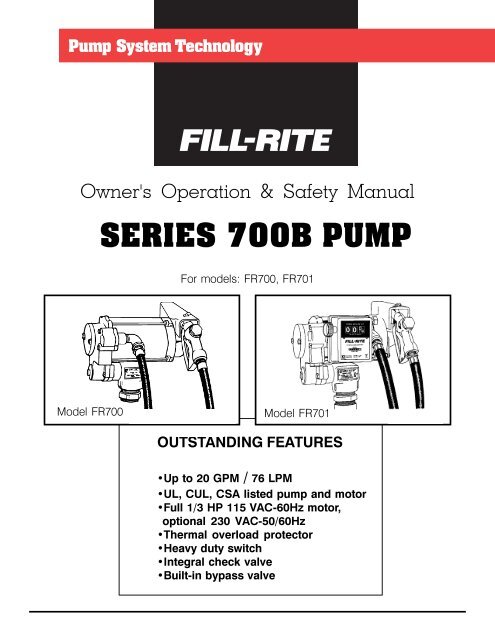
Owner's Operation & Safety Manual<br />
<strong>SERIES</strong> <strong>700B</strong> <strong>PUMP</strong><br />
For models: FR700, FR701<br />
Model FR700<br />
Model FR701<br />
OUTSTANDING FEATURES<br />
•Up to 20 GPM / 76 LPM<br />
•UL, CUL, CSA listed pump and motor<br />
•Full 1/3 HP 115 VAC-60Hz motor,<br />
optional 230 VAC-50/60Hz<br />
•Thermal overload protector<br />
•Heavy duty switch<br />
•Integral check valve<br />
•Built-in bypass valve
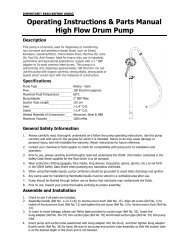
GENERAL DESCRIPTION<br />
Dear Fill-Rite Customer,<br />
Congratulations on your purchase of Fill-Rite’s new Series<br />
<strong>700B</strong> pump. We at Fill-Rite have built our worldwide<br />
reputation by designing the finest and most reliable pumps<br />
available in today’s market.<br />
Your new pump was designed with pride by some of the best<br />
and most experienced fluid control experts available. We use<br />
the most advanced technology possible to give you a pump<br />
with the superiority you deserve and the quality you’ve come<br />
to expect from Fill-Rite products.<br />
George P. Jenkins<br />
President<br />
DANGER<br />
Electrical wiring should be<br />
done by a licensed electrician<br />
in accordance with approved<br />
electrical codes. Pump<br />
should be properly grounded<br />
and a rigid conduit should be<br />
used when installing electrical<br />
wiring. Improper use or installation<br />
of this product can<br />
cause serious bodily injury or<br />
death.<br />
The Fill-Rite <strong>700B</strong> UL listed pumps are positive displacement,<br />
direct drive pumps. Depending on installation and product<br />
viscosity, these pumps can deliver up to 20 gallons of fluid per<br />
minute. Their rugged, yet lightweight design, makes for a long<br />
life of trouble-free operation.<br />
SAFETY<br />
Fill-Rite <strong>700B</strong> pumps’ safety are proven by their listing with:<br />
Underwriters Laboratories Inc., a nationally recognized<br />
independent organization for product testing<br />
to ensure public safety. Also recognized in<br />
Canada.<br />
Canadian Standards Association, a Canadian<br />
organization for product testing to ensure public<br />
safety.<br />
Certificates of compliance for safety have been obtained from<br />
Londonderry Occupation Safety Centre and Demko for the<br />
optional models marked with these logos:<br />
SAFETY INSTRUCTIONS<br />
To ensure safe and efficient operation, it is essential to<br />
read and follow each of these warnings and<br />
precautions.<br />
1. To prevent damage to pump, do not operate<br />
without the check valve (700F2661) or the check<br />
valvesubstitute (700F2679) in place.<br />
2. Do not smoke near pump or use pump near an open<br />
flame. Fire could result.<br />
3. A filter should be used on pump outlet to ensure that<br />
no foreign material is transferred to fuel tank.<br />
4. Take motors needing service to an authorized<br />
repair shop or return to factory to maintain<br />
“explosion proof” integrity.<br />
5. The pump motor is equipped with thermal overload<br />
protection. If overheated, it will shut itself off without<br />
any damage to the windings. Be sure to turn off the<br />
pump power if this occurs. As the motor cools, it will<br />
start without warning if power is on.<br />
2
OPTIONS<br />
•Full 1/3 HP 230 VAC-50/60Hz motor<br />
•Flow meters in U.S. gallons or liters<br />
•Pedestal adapters for underground tank installations<br />
•Nozzle holders for automatic nozzles<br />
•Automatic nozzles<br />
•Wiring added in motor for auxilliary equipment<br />
SKID TANK INSTALLATION<br />
Recommended Automatic Nozzles:<br />
Husky 1-GS, 1-A & 1+VIII<br />
OPW 11-A & 7-H<br />
NOTE: Using an automatic nozzle will reduce flow rate.<br />
See flow curve.<br />
)Ã$'$37(5Ã<br />
3803<br />
6.,'Ã7$1.<br />
Ã<br />
TECHNICAL INFORMATION<br />
Design Features:<br />
•Inlet: 2" male NPT on bung, 1" female NPT on suction pipe<br />
•Outlet: ¾" NPT<br />
•Built in check valve, bypass and pressure relief valves<br />
CAUTION: DO NOT INSTALL ADDITIONAL FOOT<br />
VALVE OR CHECK VALVE DURING INSTALLATION<br />
WITHOUT PRESSURE RELIEF VALVE. HOUSING<br />
OR PLUMBING CRACKING MAY RESULT.<br />
•Furnished with UL listed ¾" x 12' hose and manual nozzle<br />
•Security: Pump equipped for padlocking<br />
•Overall Dimensions:<br />
-Models FR700: 14" (356 mm) wide x 11" (279 mm) high x<br />
12" (305 mm) deep<br />
-Models FR701: 14" wide (356mm) x 11" (279 mm) high x<br />
14" (356 mm) deep<br />
•Explosion proof motor<br />
•1/3 HP 115 VAC-60hz motor, 1725 RPM, 5.5 amps<br />
•Thermal overload protection<br />
•Ball bearing construction; no greasing or oiling required<br />
•Heavy duty switch<br />
DIRECT MOUNTING INSTALLATION<br />
<br />
ÃPP<br />
<br />
ÃPP ÃPP<br />
<br />
<br />
ÃPP<br />
ÃPP<br />
Performance<br />
•22 psi (1.52 bar) maximum outlet pressure<br />
•Maximum flow rate: up to 20 gpm (76 lpm)<br />
•Maximum viscosity of fluid pumped: diesel fuel<br />
•Maximum operating ambient temperature: 150°F (66°C)<br />
•Minimum operating ambient temperature: -15°F (-26°C)<br />
(Consult factory for extreme temperature applications)<br />
•Minimum dry vacuum: 12 inches (305 mm) of mercury<br />
•Minimum suction lift: 10' (3 m) for gas & 15' (4.5m) for diesel<br />
fuel. The lift in feet is equivalent to the vertical distance from<br />
the surface of the fluid in the tank to the inlet of the<br />
pump, PLUS the friction losses through the vertical and<br />
horizontal runs of pipe, all elbows and other fittings.<br />
Systems should be designed to require a minimum<br />
amount of suction lift.<br />
ÃPD[*DVROLQH<br />
ÃPÃPD[ ÃÃÃÃ<br />
ÃPD['LHVHO<br />
ÃÃÃÃ<br />
ÃPÃPD[<br />
Ã,1<br />
ÃPP<br />
3803<br />
)Ã$'$37(5<br />
ÅÃ67'Ã3,3(Ã&283/,1*<br />
ÅÃ68&7,21Ã3,3(<br />
ÅÃ3,3(<br />
*5281'Ã/,1(<br />
7$1.Ã/,1( )/8,'Ã<br />
/(9(/<br />
(1'Ã2)Ã3,3(Ã72Ã%(Ã<br />
:,7+,1ÃÃ,1ÃÃPPÃ<br />
2)Ã7$1.Ã%27720<br />
Fluid Compatibility<br />
The <strong>700B</strong> is compatible with the following fluids:<br />
•Diesel, Gasoline, Kerosene, Mineral Spirits, Heptane,<br />
and Hexane<br />
3
RECOMMENDED ISLAND INSTALLATION<br />
<strong>PUMP</strong><br />
600F2190<br />
COUPLER<br />
700F3060<br />
<strong>PUMP</strong> BASE<br />
600F2130 PEDESTAL PIPE<br />
10' MAX.-GASOLINE<br />
3 m MAX.<br />
15' MAX.-DIESEL<br />
4.5 m MAX.<br />
FLUID<br />
LEVEL<br />
The <strong>700B</strong> is NOT compatible with the following fluids:<br />
•Acetone, Ammonia, Benzene, Bleach, Hydrochloric<br />
Acid, Ink, Toluene, and Water<br />
If in doubt about compatibility of a specific fluid, contact<br />
supplier of fluid to check for any adverse reactions to the wetted<br />
materials shown in parts list.<br />
INSTALLATION<br />
Pumps are furnished with a tank adapter for skid tank mounting;<br />
pedestals are available for island installations. All tanks<br />
must be properly vented. A pressure retaining vent-fill cap can<br />
be used to reduce fuel loss due to evaporation. Use gasoline<br />
and oil resistant pipe compound on all threaded joints. A water<br />
separator should be used for pumping diesel fuel.<br />
Pump has a built-in check valve with pressure relief to prevent<br />
fluid thermal expansion from causing unsafe system pressures.<br />
DO NOT USE ADDITIONAL CHECK VALVES OR FOOT<br />
VALVES UNLESS THEY HAVE PROPER PRESSURE RELIEF<br />
VALVES BUILT INTO THEM.<br />
Skid Tank Mounting (See illustration)<br />
1. Screw correct length of suction pipe into tank adapter<br />
(700F2170). Suction pipe should extend to 3" above bottom<br />
of tank.<br />
2. Screw tank adapter into tank.<br />
3. Mount pump on adapter.<br />
Direct Mounting to Underground Tank<br />
(See illustration)<br />
1. Cut a 2" pipe to extend to approximately 31" above the<br />
ground after installation. Thread both ends of the pipe.<br />
2. Install pipe in tank flange. Screw 2" coupling onto top of<br />
pipe.<br />
3. Install correct length of suction pipe to adapter. Suction<br />
pipe should extend to 3" above tank bottom.<br />
4. Screw tank adapter (700F2170) into coupling on 2" pipe.<br />
5. Mount pump on tank adapter.<br />
Island Installation (See illustration)<br />
1. Install tank and piping per illustration.<br />
2. Install 1" union 1/4" above island.<br />
3. Fasten suction pipe, union and coupler together.<br />
4. Slip pedestal pipe over suction pipe and fasten to<br />
coupler with set screws.<br />
5. Slide pump base onto pedestal pipe; fasten to coupler.<br />
6. Tighten union securely. Drop base into position; tighten<br />
set screws and bolt.<br />
7. Mount pump on tank adapter (700F2170).<br />
Circuit Breakers<br />
Power to the unit should be supplied from a dedicated 20 amp<br />
circuit breaker. No other equipment should be powered from<br />
this breaker. If two pumps are supplied from one breaker, that<br />
breaker must be capable of handling the load of both motors.<br />
Provision must be made to break both legs of any AC circuit.<br />
4
CALIBRATION<br />
If FR701, calibrate meter according to instructions in meter’s<br />
Owner's Operation & Safety Manual<br />
OPERATION<br />
To ensure ultimate performance, pump must be set up<br />
according to “INSTALLATION” section of this manual. On initial<br />
start-up, it may be necessary to hold nozzle open a few seconds<br />
to allow pump to prime.<br />
1. Reset meter to ‘0’ (if applicable).<br />
2. Insert nozzle in tank.<br />
3. Turn pump on.<br />
4. Begin fueling.<br />
REPAIR<br />
To maintain UL Listing, motors that need repair should be<br />
taken to an authorized repair shop or returned to factory for<br />
service. Pumps must be thoroughly flushed and drained<br />
before being taken in for service.<br />
MAINTENANCE<br />
To keep pump running at its best, periodically perform the<br />
following procedures.<br />
1. Check strainer for dirt accumulation. To clean strainer,<br />
remove strainer cover (800F4360) and pull out screen<br />
(700F2665).<br />
2. Remove rotor cover (700G7063) and inspect vanes<br />
(700F2716). Vanes should be replaced after extensive wear<br />
to prevent damage to pump.<br />
3. Check hose (700F3135) and nozzle (700F3136) for wear or<br />
damage. Bad hoses or nozzles are potential safety hazards.<br />
If FR701, see meter’s Owner's Operation & Safety Manual for<br />
its recommended maintenance procedures.<br />
<strong>700B</strong> FLOW CURVE*<br />
Discharge Presssure (PSI)<br />
25<br />
20<br />
15<br />
10<br />
5<br />
0<br />
0 2 4 6 8 10 12 14 16 18 20 22<br />
Flow in GPM<br />
C<br />
X<br />
B<br />
X<br />
A<br />
X<br />
A) FR700 with 12' of 3/4" hose and manual nozzle.<br />
B) FR700 with 12' of 3/4" hose and automatic nozzle.<br />
C) FR701 with 12' of 3/4" hose and automatic nozzle.<br />
*Nominal flow curve for reference only. Based on 3 feet suction<br />
lift. Actual flow rate may vary.<br />
5
TROUBLESHOOTING GUIDE<br />
PROBLEM POSSIBLE CAUSE SOLUTION<br />
Pump won’t prime •Suction line problem •Check for leaks in suction line.<br />
•Bypass valve open<br />
•Remove and inspect valve.<br />
•Vanes sticking<br />
•Check vanes and slots for nicks, burrs<br />
or wear.<br />
•Gasket leakage<br />
•Tighten covers and joints.<br />
•Excessive rotor or vane wear •Check rotor and vanes for excessive<br />
wear or damage.<br />
•Outlet is blocked<br />
•Check pump outlet, hose and nozzle for<br />
blockage.<br />
•Rotor key sheared or missing •Replace rotor key<br />
•Motor not operating<br />
•Rotor should turn clockwise at pump<br />
end; if not, return for repair.<br />
Pump hums but will •Dirt in pump cavity •Clean out pump cavity.<br />
not operate •Motor failure •Motor bearing(s) frozen; return for repair.<br />
Low capacity •Excessive dirt in strainer •Remove and clean strainer.<br />
•Suction line problem<br />
•Check for leaks in suction line.<br />
•Bypass valve sticking<br />
•Remove and inspect valve.<br />
•Vanes sticking<br />
•Check vanes and slots for wear.<br />
•Excessive rotor or vane wear •Check rotor and vanes for excessive<br />
wear or damage.<br />
•Hose damaged<br />
•Replace hose.<br />
Pump runs slowly •Incorrect voltage •Check incoming line voltage.<br />
•Motor failure<br />
•Motor bearing(s) failing; return for repair.<br />
Motor stalls •Bypass valve sticking •Remove and inspect valve.<br />
•Low voltage<br />
•Check incoming line voltage.<br />
•Excessive rotor or vane wear •Check rotor and vanes for excessive<br />
wear or damage.<br />
Motor overheats •Pumping high viscosity fluids •These fluids can only be pumped for<br />
short periods of time.<br />
•Clogged strainer<br />
•Remove and clean strainer.<br />
•Restricted suction pipe •Remove and clean pipe.<br />
•Motor failure<br />
•Bearing(s) tightening up; return for repair.<br />
Motor will not turn on •No power •Check incoming power source.<br />
•Motor failure<br />
•Return for repair.<br />
Fluid leakage •Bad O-ring •Check all O-ring gaskets.<br />
•Check valve not seated •Make sure check valve or check valve<br />
alternate is in place.<br />
•Dirty seal<br />
•Clean and reseat seal.<br />
•Bad seal<br />
•Replace seal.<br />
6
<strong>700B</strong> <strong>SERIES</strong> FILTER KITS<br />
Front View<br />
Top View (less pump)<br />
Parts List<br />
700KTF7023 Filter Kit (Particulate)<br />
F<br />
R<br />
7<br />
0<br />
0<br />
1<br />
2<br />
4<br />
3<br />
2<br />
I N<br />
1. *702F3400 3/4 Street El<br />
2. 702F3400 3/4 Street El<br />
3. 700F3375 3/4 X 7 Nipple<br />
4. 700ACCF7016 Filter Head<br />
700ACCF7013 Particulate<br />
Pump Filter<br />
700KTF7024 Filter Kit<br />
(Hydrosorb)<br />
1. *702F3400 3/4 Street El<br />
2. 702F3400 3/4 Street El<br />
3. 700F3375 3/4 X 7 Nipple<br />
4. 700ACCF7016 Filter Head<br />
700ACCF7012 Particulate<br />
Pump Filter<br />
701KTF7025 Filter Kit (Particulate)<br />
F<br />
R<br />
7<br />
0<br />
1<br />
1 5 4<br />
3<br />
I N<br />
1. 702F3400 3/4 Street El<br />
2. 700F3375 3/4 X 7 Nipple<br />
3. 702F3390 3/4 90° Elbow<br />
4. 702F3340 3/4 Close Nipple<br />
5. 700ACCF7016 Filter Head<br />
700ACCF7013 Particulate<br />
Pump Filter<br />
701KTF7026 Filter Kit<br />
(Hydrosorb)<br />
2<br />
1<br />
1. 702F3400 3/4 Street El<br />
2. 700F3375 3/4 X 7 Nipple<br />
3. 702F3390 3/4 90° Elbow<br />
4. 702F3340 3/4 Close Nipple<br />
5. 700ACCF7016 Filter Head<br />
700ACCF7012 Hydrosorb<br />
Pump Filter<br />
* Part included with pump; not included with kit<br />
7
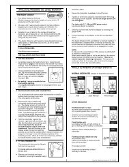
WHEN ORDERING REPAIR<br />
PARTS, BE SURE TO GIVE RE-<br />
PLACEMENT PART NUMBER,<br />
DATE OF MANUFACTURE AND<br />
<strong>PUMP</strong> <strong>SERIES</strong> NUMBER. THIS<br />
WILL ENSURE THAT THE COR-<br />
RECT REPLACEMENT PART IS<br />
SUPPLIED.<br />
'$7(Ã2)Ã0$18)$&785(<br />
0RQWK
MODELS WITH AUTOMATIC NOZZLE RETAINER<br />
ITM. PART<br />
NO. NO. DESCRIPTION QTY.<br />
.7) $XWR1R]]OHÃ5HWDLQHUÃ.LW 2SW<br />
LQFOXGHVÃLWHPVÃÃÃÃ<br />
ÃÃÃÃ<br />
) Ã+H[Ã1XW <br />
) Ã/RFNZDVKHU <br />
) 5HWDLQHUÃ%UDFNHW <br />
) 1R]]OHÃ5HWDLQHU <br />
) &RYHUÃ%UDFNHW <br />
) 1R]]OHÃ&RYHU <br />
Teflon® is a registered trademark of DuPont.<br />
<br />
9<br />
<strong>700B</strong> <strong>SERIES</strong> <strong>PUMP</strong> PARTS LIST<br />
ITM. PART<br />
MATERIAL OF<br />
NO. NO. DESCRIPTION CONSTRUCTION QTY.<br />
) 0RWRUÃÃ9ÃÃ+] 6WHHOÃ0RWRUÃ6KDIW <br />
) 0RWRUÃÃ9ÃÃ+] 6WHHOÃ0RWRUÃ6KDIW 2SW<br />
) /LQHÃ6ZLWFKÃ%HIRUHÃ <br />
) /LQHÃ6ZLWFKÃ$IWHUÃ<br />
ÃÃ,QFOXGHGÃZLWHPVÃÃÉÃ<br />
) 6ZLWFKÃ6KDIWÃ$VV\ <br />
ÃÃ,QFOXGHGÃZLWHPVÃÃÉÃ<br />
) 3XPSÃ+RXVLQJÃ &DVWÃ,URQ <br />
,QFOXGHGÃZLWHPÃ<br />
) )LEHUÃ6HDOÃ6OLQJHU <br />
.7) 6HDOÃ$VVHPEO\ Ã6WDLQOHVVÃ6WHHOÃÃ <br />
$OOLWHÃ&HUDPLFÃ<br />
DQGÃ)OXRURFDUERQ<br />
) 5RWRU ,URQ%URQ]HÃÈÈ <br />
) 5RWRUÃ.H\ /Ã6SDXOGLWH <br />
) 9DQHÃÃ&DUERQÃ0DFKLQHG &DUERQ <br />
) &KHFNÃ9DOYHÃ/DEHO <br />
) &KHFNÃ9DOYHÃ$VV\ *ODVVÃ)LOOHGÃ3RO\HVWHUÃ <br />
)OXRURFDUERQÃ=LQFÃ<br />
) 'XPP\Ã&KHFNÃ9DOYH 3ODWHGÃ6WHHOÃÃ6WDLQOHVVÃ 2SW<br />
6WHHOÃÃ%UDVVÃ6WHHOÃ<br />
DQGÃ7HIORQŠ<br />
) 25LQJÃ*DVNHWÃ %XQD1 <br />
) 25LQJÃ*DVNHWÃ %XQD1 <br />
* 5RWRUÃ&RYHU 6WHHO <br />
* Ã[ÃÃ++&6 <br />
) 3RSSHW *ODVVÃ)LOOHGÃ3RO\HVWHUÃ <br />
DQGÃ%XQD1<br />
) %\SDVVÃ6SULQJ Ã6WDLQOHVVÃ6WHHO <br />
) %\SDVVÃ&DS 6WHHO <br />
) 6WUDLQHUÃ&RYHU &DVWÃ,URQ <br />
) 25LQJÃ*DVNHWÃ %XQD1 <br />
) 6WUDLQHUÃÃ6WDQGDUGÃ0HVK Ã6WDLQOHVVÃ6WHHO <br />
7LQÃ3ODWHGÃ6WHHO<br />
) 25LQJÃ*DVNHWÃ %XQD1 <br />
) ,QOHWÃ+RXVLQJ &DVWÃ,URQ <br />
3XPSÃ1DPHSODWH <br />
* Ã5LYHW <br />
) Ã[ÃÃ++&6 <br />
* -XQFWLRQÃ%R[Ã&RYHU <br />
) Ã[ÃÃÃ++&6 <br />
) Ã/RFNÃ1XW <br />
) 6ZLWFKÃ/HYHU <br />
) ÆÃ[ÃÃ'ULYHÃ6FUHZ <br />
) /RFNLQJÃ/LQN <br />
) Ã6SULQJÃ:DVKHU <br />
) 1R]]OHÃ&RYHUÃ <br />
) 25LQJÃ*DVNHWÃ %XQD1 <br />
& Ã0HWHUÃ0RGHOÃ)5 <br />
&/ Ã/LWHUÃ0HWHUÃ0RGHOÃ)5/ 2SW<br />
) 6WUHHWÃ(OÃ0RGHOÃ)5 *DOYDQL]HGÃ6WHHO <br />
) Ã8/Ã/LVWHGÃ+RVH <br />
) ÅÃ1ROHDGÃ1R]]OH <br />
) $XWRPDWLFÃ1R]]OHÃ 2SW<br />
1ROHDGÃ6SRXWÃ1RWÃ6KRZQ<br />
) $XWRPDWLFÃ1R]]OHÃ 2SW<br />
6SRXWÃ+RRNÃ1RWÃ6KRZQ<br />
) 7DQNÃ$GDSWHU <br />
.7) %Ã5HSDLUÃ3DUWVÃ.LW<br />
,QFOXGHVÃ,WHPVÃÃÃÃÃ<br />
ÃÃÃÃÃÉÃ<br />
.7)Ã6HDOÃ.LW<br />
.7) 6HDOÃ.LWÃ,QFOXGHVÃ,WHPVÃ<br />
ÃÉÃ)Ã6HDOÃ7RRO<br />
MODELS WITHOUT 800 METER (Replaces items 41 & 42)<br />
) 'LVFKDUJHÃ$VV\ 2SW<br />
) 2XWOHWÃ)LWWLQJÃ0RGHOÃ $OXPLQXP <br />
) 25LQJÃ*DVNHWÃ %XQD1 <br />
) 6WUHHWÃ(O *DOYDQL]HGÃ6WHHO
<strong>700B</strong> <strong>SERIES</strong> ANTI-SIPHON KIT 700KTF0065<br />
PARTS INCLUDED IN KIT<br />
PART DESCRIPTION QTY.<br />
702F1882 Siphon Break 1<br />
700F0651 Bung Adapter 1<br />
)<br />
'<br />
%<br />
&<br />
$<br />
PARTS REQUIRED BUT NOT<br />
INCLUDED IN KIT<br />
NO. DESCRIPTION QTY.<br />
A 1/4" Tubing 1<br />
B 1/4" Compression Fitting 2<br />
C 3/4" Tee 1<br />
D 3/4" Nipple 1<br />
)<br />
%<br />
%<br />
PARTS REQUIRED BUT NOT<br />
INCLUDED IN KIT<br />
NO. DESCRIPTION QTY.<br />
A 1/4" Tubing 1<br />
B 1/4" Compression Fitting 2<br />
C 3/4" Tee 1<br />
D 3/4" Nipple 1<br />
$<br />
'<br />
&<br />
)<br />
)<br />
%<br />
10
NOTES<br />
11
Fill-Rite: A Worldwide<br />
Reputation for Reliability.<br />
For over 50 years, people all over the world who have<br />
needed tough, dependable pumps have insisted on Fill-<br />
Rite products. For them, Fill-Rite has been “the reliable<br />
pump” that keeps on working even under the toughest<br />
of conditions. We’re proud of the reputation our hand<br />
pumps, DC and AC pumps and meters have earned.<br />
Today they’re only a part of the rapidly expanding Fill-<br />
Rite line.<br />
Applying the Science<br />
of Fluid Transfer.<br />
An active research and development program is the<br />
centerpiece of our ongoing commitment to respond to<br />
new fluid transfer opportunities. This has led to new<br />
products and to new technologies and new facilities to<br />
produce these products.<br />
To bring this advanced technology to market, we have<br />
invested in precision engineering and testing<br />
equipment. This improves our ability to produce fluid<br />
handling equipment that meets market demands for<br />
quality, performance and price.<br />
A Hard Working<br />
Support Network.<br />
Just as important as these capabilities are the people<br />
behind them - our design and production personnel.<br />
They give you the ability to specify systems that meet<br />
the most challenging of applications. With them, you<br />
can be assured of prompt, intelligent answers to your<br />
fluid transfer questions.<br />
To service customers in the field, we’ve put together a<br />
select, well-monitored team of distributors. Throughout<br />
the world, they are ready to help you with technical<br />
advice, ordering and delivery.<br />
Fill-Rite will always stand for reliable pumps and fluid<br />
handling equipment. We’ll continue to develop new<br />
products and production techniques to keep pace with<br />
ever changing technologies. Each of our products will<br />
always be made with the same care and quality that<br />
made our pumps famous.<br />
Tuthill Transfer Systems (“Manufacturer”) warrants to each buyer of its Fill-<br />
Rite products (the “Buyer”) for a period of 12 months from date of invoice or<br />
sales receipt, but in no event more than 18 months from date of manufacture,<br />
that goods of its manufacture (“Goods”) will be free from defects of material<br />
and workmanship. Manufacturer’s sole obligation under the foregoing<br />
warranties will be limited to either, at Manufacturers’ option, replacing or<br />
repairing defective Goods (subject to limitations hereinafter provided) or<br />
refunding the purchase price for such Goods theretofore<br />
paid by the Buyer, and Buyer’s exclusive remedy for<br />
breach of any such warranties will be enforcement of such<br />
obligations of Manufacturer. If Manufacturer so requests<br />
the return of the Goods, the Goods will be redelivered<br />
to Manufacturer in accordance with Manufacturer’s<br />
instructions F.O.B. Factory. The remedies contained<br />
herein shall constitute the sole recourse of the Buyer<br />
against Manufacturer for breach of warranty. IN NO<br />
EVENT SHALL MANUFACTURER’S LIABILITY ON<br />
ANY CLAIM FOR DAMAGES ARISING OUT OF THE MANUFACTURE SALE,<br />
DELIVERY OR USE OF THE GOODS EXCEED THE PURCHASE PRICE OF<br />
THE GOODS. The foregoing warranties will not extend to Goods subjected<br />
to misuse, neglect, accident or improper installation or maintenance, or<br />
which have been altered or repaired by anyone other than Manufacturer or<br />
its authorized representative. THE FOREGOING WARRANTIES ARE<br />
EXCLUSIVE AND IN LIEU OF ALL OTHER WARRANTIES OF MERCHANT-<br />
ABILITY, FITNESS FOR PURPOSE OF ANY OTHER TYPE,<br />
WHETHER EXPRESS OR IMPLIED. No person may vary<br />
the foregoing warranties and remedies except in writing<br />
signed by a duly authorized officer of Manufacturer.<br />
Warranties or remedies that differ from the foregoing<br />
shall not otherwise be binding on Manufacturer. The<br />
Buyer’s acceptance of delivery of the Goods<br />
constitutes acceptance of the foregoing warranties<br />
and remedies, and all conditions and<br />
limitations thereof.<br />
F3392 REV. 13