Thyristors in Railway Traction How can their effects be measured?
Thyristors in Railway Traction How can their effects be measured?
Thyristors in Railway Traction How can their effects be measured?

You also want an ePaper? Increase the reach of your titles
YUMPU automatically turns print PDFs into web optimized ePapers that Google loves.
4<br />
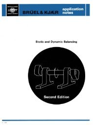
Waveform record<strong>in</strong>g of 25 kV 50 Hz thyristor<br />
locomotive primary current at approximately<br />
90° advance on second rectifier bridge (1<br />
div. - 24 Amps). Second bridge is <strong>in</strong>dicated<br />
by the fact that the two 'steps' <strong>in</strong> the cycle<br />
are staggered by about 220 Amps. It <strong>can</strong> <strong>be</strong><br />
deduced that the armature current is approximately<br />
110 Amps, multiplied by the transformer<br />
turns ratio (referred to one secondary),<br />
divided by the num<strong>be</strong>r of armatures <strong>in</strong> parallel.<br />
Quite a lot <strong>can</strong> therefore <strong>be</strong> determ<strong>in</strong>ed<br />
even from one waveform<br />
o_^_^-.\-. -y-ys jK o_^_^-.\-. -y-ys ~' B<br />
jK ~' B<br />
•<br />
___ ___...____...______._______ ___________ _^_ j , m - p«^^«_ - ^^^_ - _ - ^^^^ , _ - _ - _ - _ - _ - ^^^^^^^_ - ^^^^^^^^^^^^^^^^^^^^^^^^_ - ^^^^^^^^ , ^^-r --- ^^ I pw-'-'q , q , ^-r'iw^ , f , pw_ l _ - f^^ , _ - _ - r^^^^_ - _ - _ - ^^^_ - ^^^^^_ - ^^^^^_ - ^^^^_ - ^^^^_ - _ - ^^^^_ - _ - ^^^^^H<br />
■■■-■-■■ L "-"- - __C'! j ■■■-■-■■ _^_^_t ^__^__J^__^__H^_P__^__^B__^__i __^__^__H^__^__H^_I^__H^_^_K *_B<br />
L "-"- - __C'! j _^_^_t ^__^H^__^__H^_P__^__^B__^__i __^__^__H^__^__H^_I^__H^_^_K ■T<br />
-■H^B-. ^>». ^-^». :■>■>.- :■>■>, ■9B3EH K_3_E3_E_i_l K__^E_H_^H ■<br />
W BBBfl B-B-BB I<br />
___■. ._■ \ \\ . ^ X -^- V v<br />
. ^^^MBM* ^^^Mgmj » - ^-> ^P«^^^W^^ffW^ mtm am, ^- v- — ■—— — -<br />
«u «ti • .%... ♦ #? #F » #<br />
Waveform record<strong>in</strong>g (left) of thyristor locomotive<br />
primary voltage (upper trace) and current<br />
{lower trace), made with B & K Type<br />
6302 portable two-channel Waveform Retriever<br />
(above) and Type 2309 Portable Two-<br />
Channel Level Recorder (p.16). The Waveform<br />
Retriever is an <strong>in</strong>strument for enabl<strong>in</strong>g<br />
accurate chart record<strong>in</strong>gs to <strong>be</strong> made of repetitive<br />
waveforms with frequency components<br />
up to 10 kHz, even when the wanted<br />
signal is buried <strong>in</strong> noise. In this record<strong>in</strong>g 1<br />
division = 7,5 kV and 24 Amps vertically and<br />
2,8 ms horizontally.<br />
The current waveform shows that the locomotive<br />
has about 80° of advance on one rectifier<br />
bridge. This <strong>can</strong> <strong>be</strong> deduced from the<br />
fact that the current l<strong>in</strong>gers at zero amps for<br />
two signifi<strong>can</strong>t parts of the cycle. Furthermore<br />
the marked r<strong>in</strong>g<strong>in</strong>g on the voltage<br />
waveform occurs just after each voltage<br />
peak. Note that commutation from thyristors<br />
to diodes (at the trail<strong>in</strong>g edge of each current<br />
peak) causes almost no perturbation on<br />
the voltage waveform. The waveforms are recorded<br />
<strong>in</strong> <strong>their</strong> correct time-relationship with<br />
this arrangement of <strong>in</strong>struments, and the lagg<strong>in</strong>g<br />
power factor is easily observed