Thyristors in Railway Traction How can their effects be measured?
Thyristors in Railway Traction How can their effects be measured?
Thyristors in Railway Traction How can their effects be measured?

You also want an ePaper? Increase the reach of your titles
YUMPU automatically turns print PDFs into web optimized ePapers that Google loves.
18-060
Introduction<br />
Although there are many different<br />
standard voltages and several different<br />
frequencies <strong>in</strong> use for electric<br />
railway traction supplies, all such<br />
systems <strong>be</strong>long to one of two broad<br />
groups — AC or DC.<br />
The earliest electrifications used<br />
DC <strong>be</strong>cause it was cheap and simple<br />
to construct electric motors<br />
which would run directly off the<br />
l<strong>in</strong>eside supply. DC is still widely<br />
used for<br />
railways.<br />
suburban and commuter<br />
absorbs signifi<strong>can</strong>t amounts of en- sier to use <strong>in</strong> AC traction systems,<br />
For railway electrification over ergy and generates a good deal of where the alternations of the supply<br />
long distances, AC is preferred for heat, especially on commuter tra<strong>in</strong>s ensure that it switches off.<br />
the same reason as it is preferred subjected to frequent stopp<strong>in</strong>g and<br />
for the public electricity supply — it start<strong>in</strong>g. Alongside the track are laid<br />
may <strong>be</strong> transmitted at a high vol- cables carry<strong>in</strong>g telephone circuits,<br />
tage (and low current) — and trans- <strong>Thyristors</strong> offer the promise of re- signall<strong>in</strong>g circuits and tra<strong>in</strong> control<br />
formed at the po<strong>in</strong>t of use to a low duced weight, reduced ma<strong>in</strong>tenance circuits. It is a feature of electrified<br />
voltage (and high current). and reduced cost — especially on railways that there is a need to lay<br />
AC systems. Additionally, there is light-current cables for long dis-<br />
It is a feature of electric motors considerable scope for reduc<strong>in</strong>g the tances <strong>be</strong>side electric power cables,<br />
used for railway propulsion that the energy consumption of tra<strong>in</strong>s, both and immunisation aga<strong>in</strong>st <strong>in</strong>duced<br />
voltage applied to the mach<strong>in</strong>e must by elim<strong>in</strong>at<strong>in</strong>g the resistances and currents and voltage <strong>in</strong> the light-cur<strong>be</strong><br />
controlled over quite a wide by permitt<strong>in</strong>g k<strong>in</strong>etic energy from a rent cable is established practice.<br />
range — typically 30:1 — to accom- tra<strong>in</strong> slow<strong>in</strong>g down to <strong>be</strong> chan- <strong>How</strong>ever, thyristor traction usually<br />
modate the slowly chang<strong>in</strong>g speed nelled back to the l<strong>in</strong>eside electric- comes as replacement equipment to<br />
of the tra<strong>in</strong>, and this is where thyris- ity supply for use by the other tra<strong>in</strong>s an exist<strong>in</strong>g railway, with all the<br />
tors are attractive. (regenerative brak<strong>in</strong>g). light-current circuits immunised<br />
Established practice on DC sys- These <strong>be</strong>nefits, which as we shall<br />
only for conventional traction units,<br />
for which the problems are much<br />
terns is to <strong>in</strong>sert variable resist- see have to <strong>be</strong> paid for, arise by vir- less severe.<br />
ances <strong>in</strong> the motor circuits, and re- tue of the property of the thyristor<br />
group motors <strong>in</strong> series and parallel of <strong>be</strong><strong>in</strong>g able to switch very large It is therefore very important at<br />
to achieve this control. On AC sys- currents very rapidly with no mov- an early stage to measure and analterns,<br />
motor voltage may <strong>be</strong> varied <strong>in</strong>g parts. Both on AC and DC sys- yse the audio frequency currents <strong>in</strong>by<br />
select<strong>in</strong>g taps on the trans- terns it controls the traction motor jected by a thyristor traction equipformer.<br />
Both these techniques re- voltage by act<strong>in</strong>g as a variable mark- ment <strong>in</strong>to its supply. To a limited<br />
quire heavy-current switch<strong>in</strong>g-con- space-ratio device, switch<strong>in</strong>g on extent this may <strong>be</strong> done on the testtacts<br />
which must <strong>be</strong> very heavy and off many times per second. It is <strong>be</strong>d. <strong>How</strong>ever, the real test comes<br />
and robust to avoid frequent failure much easier to switch on than off, when the equipment gets on to a<br />
and ma<strong>in</strong>tenance. Series resistance and so thyristors are somewhat ea- tra<strong>in</strong> and out on the track, <strong>be</strong>cause<br />
a traction supply, with all its resonances<br />
and frequency-dependant<br />
characteristics, <strong>can</strong> <strong>in</strong>fluence considerably<br />
the distribution of harmonics.<br />
The ultimate test is the level of<br />
harmonic currents <strong>in</strong>duced <strong>in</strong> the<br />
light-current circuits. Neither of<br />
these phenomena <strong>can</strong> <strong>be</strong> realistically<br />
exam<strong>in</strong>ed on the test <strong>be</strong>d<br />
alone. At the same time, track trials<br />
are difficult and costly to organise,<br />
usually call<strong>in</strong>g for full occupation of<br />
a busy railway, so it is essential<br />
that all the right <strong>in</strong>formation is obta<strong>in</strong>ed<br />
first time round. The methods<br />
descri<strong>be</strong>d <strong>in</strong> the follow<strong>in</strong>g <strong>in</strong>di-<br />
lllustration of the <strong>effects</strong> of a tra<strong>in</strong> with AC thyristor traction control equipment on track cir- Cate how this may <strong>be</strong> achieved.<br />
cuits and telecomms circuits<br />
1
TflnP RPCOrH thfi a " the ' n f° rmat ' on aD0Ut the test. In most cases low-level monitor-<br />
" The temptation should <strong>be</strong> resisted <strong>in</strong>g devices, such as current trans-<br />
TGStS t0 conserve tape by reduc<strong>in</strong>g the formers, will <strong>be</strong> <strong>in</strong>stalled to enable<br />
speed to 1,5 i.p.s. for this part of a tape-recorder to <strong>be</strong> connected<br />
The end product of a thyristor trac- the record<strong>in</strong>g. The <strong>in</strong>formation to <strong>be</strong> safely to the traction circuits.<br />
tion trial is to test the performance given <strong>in</strong> the <strong>in</strong>troduction might run<br />
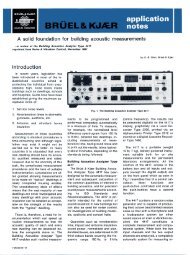
of the locomotive or tra<strong>in</strong> and deter- as follows: The Bruel & Kjaer Type 7003 tapem<strong>in</strong>e<br />
its effect on the telecomms recorder fulfills all the requirements<br />
and signall<strong>in</strong>g circuits. This is 1. Identity of the commentator for this application. Here are its feaachieved<br />
by a process of data reduc- 2. Today's date tures:<br />
tion performed on a whole host of 3. Tape speed<br />
measurements. In other words, 4. "Tape counter set to zero — * 4-channel FM record<strong>in</strong>gs to IRIG<br />
many measurements must <strong>be</strong> Now!" Wideband Group 1 Standard on<br />
taken, much data collected, and a 5. The location quarter-<strong>in</strong>ch tape, so you <strong>can</strong> rerelatively<br />
simple result obta<strong>in</strong>ed — 6. The vehicle <strong>be</strong><strong>in</strong>g tested serve your 7003 for trials use<br />
<strong>in</strong> extreme, perhaps either "Yes, 7. The identity of the signal re- and replay the record<strong>in</strong>gs on bigthe<br />
locomotive may run" or "No, corded on each tape track ger, heavier mach<strong>in</strong>es kept permthe<br />
locomotive is not good enough 8. The sensitivity sett<strong>in</strong>gs of each anently <strong>in</strong> the laboratory<br />
to run". channel <strong>in</strong> terms of 40% FM car- * Flat response from DC to 10 kHz<br />
rier deviation (e.g., pantograph- with no phase shift at low fre-<br />
A trials tra<strong>in</strong> — especially the current = 300 amps, tra<strong>in</strong> speed quencies, for correct reproduccramped<br />
quarters on a locomotive = 200km/hr etc.) tion of waveforms as well as sig-<br />
— is not the <strong>be</strong>st place to perform 9. Details of tests, e.g.: nal levels<br />
this process of data reduction. Fur- runn<strong>in</strong>g-l<strong>in</strong>e and direction * The first <strong>in</strong>strumentation FM<br />
thermore, the process itself may <strong>be</strong> make-up of test tra<strong>in</strong> tape recorder to <strong>be</strong> designed spe<strong>in</strong>fluenced<br />
by the results obta<strong>in</strong>ed. traction motor current cifically for use <strong>in</strong> the field, only<br />
In other words, when one knows any special modifications to the 7,6 kg (16,8 1b) weight and 100<br />
more about the system, one may vehicle x 270 x 380 mm (4 x 11 x 15 <strong>in</strong>)<br />
want to concentrate on measur<strong>in</strong>g <strong>in</strong> size<br />
different aspects of it. Remem<strong>be</strong>r also to calibrate each * 24 m<strong>in</strong>utes of cont<strong>in</strong>uous record-<br />
FM channel of the tape recorder <strong>be</strong>- <strong>in</strong>g at 15 <strong>in</strong>ches per second,<br />
For this reason it is most import- forehand, <strong>be</strong>cause there are always with the facility for 4 hours conant<br />
to make <strong>in</strong>strumentation tape-re- go<strong>in</strong>g to <strong>be</strong> requirements to know t<strong>in</strong>uous record<strong>in</strong>g at 1,5 i.p.s.<br />
cord<strong>in</strong>gs of all the <strong>in</strong>formation the absolute levels of the currents and reduced bandwidth<br />
likely to <strong>be</strong> needed, and perform and voltages subsequently. * Versatile power requirements —<br />
most of the analysis <strong>in</strong> the more choice of <strong>in</strong>ternal rechargeable<br />
congenial conditions of the labora- At the l<strong>in</strong>eside it is necessary to supply, external 12V vehicle battery<br />
afterwards. That way, you <strong>can</strong> make record<strong>in</strong>gs of telephone cir- tery supply or ma<strong>in</strong>s 50—400 Hz<br />
ensure that a costly trial conducted cuit noise, substation current and 100—240V<br />
<strong>in</strong> the middle of the night, miles voltage, and (on DC electrified l<strong>in</strong>es) * Better than 1% DC drift<br />
from anywhere, isn't wasted. <strong>in</strong>duced signals <strong>in</strong> track circuits. * Standard BNC signal connections<br />
On board the tra<strong>in</strong>, the most important<br />
quantities to record are the<br />
traction current and traction voltage<br />
waveforms. It helps, too, to record<br />
the tra<strong>in</strong> speed, either by means of<br />
a pick-off from the driver's speedometer<br />
if this is available, or by<br />
monitor<strong>in</strong>g traction motor voltage.<br />
<strong>How</strong>ever, it is not essential to record<br />
speed automatically <strong>be</strong>cause<br />
the tape-record<strong>in</strong>g should carry a<br />
voice track on which all important<br />
<strong>in</strong>formation about each part of the<br />
trial is recorded, <strong>in</strong>clud<strong>in</strong>g the<br />
speed from moment to moment.<br />
The tape-recorder releases the trials<br />
eng<strong>in</strong>eer from the pencil-and-paper<br />
rout<strong>in</strong>e, so he has plenty of time to<br />
voice all his thoughts.<br />
Before commenc<strong>in</strong>g the trial, the<br />
eng<strong>in</strong>eer should tape-record an <strong>in</strong>troduction<br />
on the voice track list<strong>in</strong>g The B8tK Type 7003 4-channel FM Instrumentation Tape Recorder<br />
2
Monitor<br />
what is go<strong>in</strong>g on<br />
You may not want to do much analysis<br />
of signals dur<strong>in</strong>g a trial, but it<br />
is important to know you are record<strong>in</strong>g<br />
the right signal, and not ma<strong>in</strong>s<br />
hum or someth<strong>in</strong>g totally unexpected.<br />
A two-channel oscilloscope<br />
<strong>in</strong> the cab of the tra<strong>in</strong>, at the substation<br />
or the telephone junction box<br />
will tell you a lot of th<strong>in</strong>gs quickly<br />
and keep you <strong>in</strong>formed about the<br />
test. For example, on an AC system<br />
the traction voltage waveform tends<br />
to <strong>be</strong> s<strong>in</strong>usoidal close to the substation,<br />
but at other locations the presence<br />
of a load (not necessarily the<br />
trials tra<strong>in</strong>) will cause the l<strong>in</strong>e to<br />
"r<strong>in</strong>g" electrically at quite high har-<br />
Typical connection diagram for oscilloscope and tape recorder on board a trials locomotive<br />
monies of the supply, and with a lit- important to get a good l<strong>in</strong>ear distle<br />
experience it is possible to deter- play and negligible phase shift at<br />
m<strong>in</strong>e which are the dom<strong>in</strong>ant har- low frequencies.<br />
monies. The ideal traction current<br />
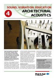
waveform is square, but <strong>in</strong> practice The Bruel & Kjaer Type 4714 is<br />
its shape quickly reveals the speed one of the smallest measurement<br />
of the tra<strong>in</strong> and its approximate oscilloscopes available, <strong>be</strong>cause it<br />
power factor, as well as the level of has <strong>be</strong>en designed to fit <strong>in</strong>to the<br />
harmonics. B & K Module System alongside<br />
other compact, portable <strong>in</strong>stru-<br />
As with the tape-recorder, the re- ments. It has the follow<strong>in</strong>g features:<br />
quirement is for maximum portability<br />
and, preferably, <strong>in</strong>dependence of * 2,0 to 2,2 kg (4,4 to 4,85 lb —<br />
a ma<strong>in</strong>s supply. There is no require- depend<strong>in</strong>g on power source)<br />
The B&K Type 4714 Portable 2-channei ment for extra features like delayed weight, 133 x 105 x 200mm<br />
Oscilloscope sweep or high sensitivity, but it is (5,23 x 4,12 x 7,88 <strong>in</strong>) size —<br />
easily lost <strong>in</strong> a locomotive driv<strong>in</strong>gcab!<br />
* Can <strong>be</strong> powered either from <strong>in</strong>ternal<br />
6,3 V rechargeable battery<br />
pack giv<strong>in</strong>g 5 hours' operation<br />
per charge, or an <strong>in</strong>ternal ma<strong>in</strong>s<br />
adaptor for 100 — 230 V 50 —<br />
60 Hz ma<strong>in</strong>s operation (a compartment<br />
<strong>in</strong> the body of the<br />
'scope will accommodate either<br />
of these items, which may <strong>be</strong><br />
quickly changed over <strong>in</strong> the field)<br />
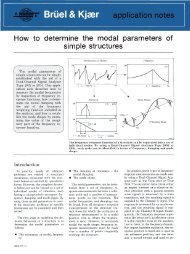
Waveform record<strong>in</strong>g of the build-up of pantograph current <strong>in</strong> a 50 Hz thyristor locomotive dur<strong>in</strong>g<br />
the first 680 ms of the application of power. Note the highly distorted waveform. 1 division<br />
= 24 A. The record<strong>in</strong>g was made us<strong>in</strong>g a Type 7502 Digital Event Recorder and a Type 2307 Level<br />
Recorder<br />
* DC to 5 MHz bandwidth, ± 5% calibrated<br />
ga<strong>in</strong>s on both channels of<br />
0,03; 0,1; 0,3; 1 V per division<br />
* Calibrated time-base 1//s to<br />
100 ms per division with full trigger<strong>in</strong>g<br />
facilities<br />
* Standard BNC signal connections<br />
3
4<br />
Waveform record<strong>in</strong>g of 25 kV 50 Hz thyristor<br />
locomotive primary current at approximately<br />
90° advance on second rectifier bridge (1<br />
div. - 24 Amps). Second bridge is <strong>in</strong>dicated<br />
by the fact that the two 'steps' <strong>in</strong> the cycle<br />
are staggered by about 220 Amps. It <strong>can</strong> <strong>be</strong><br />
deduced that the armature current is approximately<br />
110 Amps, multiplied by the transformer<br />
turns ratio (referred to one secondary),<br />
divided by the num<strong>be</strong>r of armatures <strong>in</strong> parallel.<br />
Quite a lot <strong>can</strong> therefore <strong>be</strong> determ<strong>in</strong>ed<br />
even from one waveform<br />
o_^_^-.\-. -y-ys jK o_^_^-.\-. -y-ys ~' B<br />
jK ~' B<br />
•<br />
___ ___...____...______._______ ___________ _^_ j , m - p«^^«_ - ^^^_ - _ - ^^^^ , _ - _ - _ - _ - _ - ^^^^^^^_ - ^^^^^^^^^^^^^^^^^^^^^^^^_ - ^^^^^^^^ , ^^-r --- ^^ I pw-'-'q , q , ^-r'iw^ , f , pw_ l _ - f^^ , _ - _ - r^^^^_ - _ - _ - ^^^_ - ^^^^^_ - ^^^^^_ - ^^^^_ - ^^^^_ - _ - ^^^^_ - _ - ^^^^^H<br />
■■■-■-■■ L "-"- - __C'! j ■■■-■-■■ _^_^_t ^__^__J^__^__H^_P__^__^B__^__i __^__^__H^__^__H^_I^__H^_^_K *_B<br />
L "-"- - __C'! j _^_^_t ^__^H^__^__H^_P__^__^B__^__i __^__^__H^__^__H^_I^__H^_^_K ■T<br />
-■H^B-. ^>». ^-^». :■>■>.- :■>■>, ■9B3EH K_3_E3_E_i_l K__^E_H_^H ■<br />
W BBBfl B-B-BB I<br />
___■. ._■ \ \\ . ^ X -^- V v<br />
. ^^^MBM* ^^^Mgmj » - ^-> ^P«^^^W^^ffW^ mtm am, ^- v- — ■—— — -<br />
«u «ti • .%... ♦ #? #F » #<br />
Waveform record<strong>in</strong>g (left) of thyristor locomotive<br />
primary voltage (upper trace) and current<br />
{lower trace), made with B & K Type<br />
6302 portable two-channel Waveform Retriever<br />
(above) and Type 2309 Portable Two-<br />
Channel Level Recorder (p.16). The Waveform<br />
Retriever is an <strong>in</strong>strument for enabl<strong>in</strong>g<br />
accurate chart record<strong>in</strong>gs to <strong>be</strong> made of repetitive<br />
waveforms with frequency components<br />
up to 10 kHz, even when the wanted<br />
signal is buried <strong>in</strong> noise. In this record<strong>in</strong>g 1<br />
division = 7,5 kV and 24 Amps vertically and<br />
2,8 ms horizontally.<br />
The current waveform shows that the locomotive<br />
has about 80° of advance on one rectifier<br />
bridge. This <strong>can</strong> <strong>be</strong> deduced from the<br />
fact that the current l<strong>in</strong>gers at zero amps for<br />
two signifi<strong>can</strong>t parts of the cycle. Furthermore<br />
the marked r<strong>in</strong>g<strong>in</strong>g on the voltage<br />
waveform occurs just after each voltage<br />
peak. Note that commutation from thyristors<br />
to diodes (at the trail<strong>in</strong>g edge of each current<br />
peak) causes almost no perturbation on<br />
the voltage waveform. The waveforms are recorded<br />
<strong>in</strong> <strong>their</strong> correct time-relationship with<br />
this arrangement of <strong>in</strong>struments, and the lagg<strong>in</strong>g<br />
power factor is easily observed
Psophometric n o i s e<br />
T h e p *°? h ?T- T Y voltage<br />
^ r a n g e s (at 10dB <strong>in</strong>tervals, i.e., *<br />
if! telephone C i r C U i t S 3 , 1 6 <strong>in</strong>crements of sensitivity) from<br />
100/A/ to 30V RMS full scale def-<br />
On AC systems the h a r m o n i c s l e c t i o n , and a built-<strong>in</strong> calibration<br />
produced by thyristor control e q u i p - s o u r c e which may <strong>be</strong> used without<br />
ments tend to lie at lower audio f r e - d i s t u r b i n g the range sett<strong>in</strong>g, and<br />
quencies than on DC s y s t e m s , w h i c h also permits subsequent <strong>in</strong>ma<strong>in</strong>ly<br />
with<strong>in</strong> the restricted b a n d - s t r u m e n t a t i o n (such as a level recorwidth<br />
used for telephone c i r c u i t s . d e r ) to <strong>be</strong> calibrated at the same<br />
Furthermore, the lengths of t h e s e t i m e .<br />
circuits are longer on <strong>in</strong>ter-city<br />
routes (which are usually AC e l e c t r i - A versatile selection of outputs is<br />
fied) than on commuter r o u t e s , a v a i l a b l e for record<strong>in</strong>g and monitor-<br />
(which are generally DC electrified), <strong>in</strong>g purposes. There is an AC output<br />
<strong>in</strong>creas<strong>in</strong>g the coupl<strong>in</strong>g <strong>be</strong>tween Type 2429 Psophometer (on a BNC socket) provid<strong>in</strong>g 3,16 V<br />
cables. Telephone <strong>in</strong>terference is RMS out from a low impedance at<br />
therefore more of a problem when full scale deflection, with a peak<br />
thyristors are <strong>in</strong>troduced on AC sys- sured with it as psophometric capability of 14 V. There is a DC outtems,<br />
than on DC systems. It is also noise. put (also on a BNC socket) with less<br />
worse generally on the newer <strong>in</strong>dus- than 50O source impedance,<br />
trial-frequency electrifications (50 The Bruel & Kjaer Type 2429 pso- + 3,16V DC at full scale deflection<br />
and 60 Hz) than the older "railway" phometer conforms to the require- and a peak capability of + 14 V. L<strong>in</strong>frequency<br />
systems (16-2/3 and ments of CCITT P53 and DIN earity of this signal aga<strong>in</strong>st <strong>in</strong>put<br />
25 Hz) <strong>be</strong>cause the predom<strong>in</strong>ant 45 405 for telephone circuit noise RMS level is <strong>be</strong>tter than ±2,3% of<br />
harmonics from the latter lie at measurement. It may <strong>be</strong> used at the level <strong>be</strong>tween 25% and 78% of melower<br />
frequencies, outside the tele- site of the trials, powered from a ter full scale deflection, and <strong>be</strong>tter<br />
phone bandwidth (usually 200Hz to pair of external batteries (18 to than ±6% of level <strong>be</strong>tween 8% and<br />
3 kHz) and there is less excitation of 25V), or <strong>in</strong> the laboratory (to mea- 245% of meter full scale deflection.<br />
transmission l<strong>in</strong>e resonances. Be- sure the signal recorded on tape). There is a headphone outlet on a<br />
cause the quality of telephone powered from 50 to 400 Hz, 100 to pair of screw term<strong>in</strong>als capable of<br />
speech is not usually higher than it 250V ma<strong>in</strong>s. Connection to a tele- accept<strong>in</strong>g bare wires or banana<br />
needs to <strong>be</strong> for <strong>in</strong>telligibility, for^ rea- phone circuit is made us<strong>in</strong>g a 3-p<strong>in</strong> plugs. F<strong>in</strong>ally there is a 7-p<strong>in</strong> DIN<br />
sons of economics, some <strong>in</strong>terfer- plug to DIN 41 628 (B & K part no. socket carry<strong>in</strong>g both AC and DC outence<br />
from electric traction units is JP 0316). The <strong>in</strong>put <strong>in</strong>cludes a puts, battery <strong>in</strong>puts, and a l<strong>in</strong>e for<br />
generally tolerated, and the levei of transformer provid<strong>in</strong>g symmetry and an external capacitor which may <strong>be</strong><br />
immunisation on telephone circuits a high level of isolation from poten- connected to <strong>in</strong>crease the averag<strong>in</strong>g<br />
is chosen to provide the <strong>be</strong>st com- tially hazardous voltages which may time of the RMS detector.<br />
promise <strong>be</strong>tween cost and <strong>in</strong>telligi- <strong>be</strong> <strong>in</strong>duced <strong>in</strong> the telephone circuit<br />
bility. <strong>How</strong>ever, when a new elec- from the traction supply.<br />
trie traction unit is <strong>in</strong>troduced to an<br />
exist<strong>in</strong>g system and generates a different<br />
pattern of <strong>in</strong>terference, its effect<br />
on <strong>in</strong>telligibility must <strong>be</strong> <strong>measured</strong>.<br />
Intelligibility is a subjective matter.<br />
Different frequencies <strong>in</strong>terfere<br />
more or less with speech, and the<br />
annoyance level of a given frequency<br />
is also dependant on the<br />
bandwidth of the wanted speech signal.<br />
Consequently, to measure<br />
noise objectively <strong>in</strong> a telephone circuit<br />
one needs both a measur<strong>in</strong>g<br />
amplifier and a weight<strong>in</strong>g filter to<br />
weight the different frequencies accord<strong>in</strong>g<br />
to the results of statistical<br />
experiments on human subjects.<br />
The weight<strong>in</strong>g filter used for this<br />
purpose is known as a pSOphome- Response curves for Telephone Weight<strong>in</strong>g and Unweighted characteristics of the Type 2429<br />
trie filter and the COmDlete <strong>in</strong>stru- Psophometer. Note that both the amplitude and frequency axes of this graph are logarithmic, <strong>in</strong><br />
, . ,x . , contrast to the spectra on pages 7 to 14. A logarithmic frequency scale is useful for frequency<br />
ment is a psophometer. It is also . . ,+ . . *i . . .. . +. . . ,. . ' . ^ , . .<br />
K K analysis of transmission paths (of which the ear and an electrical network are two examples), al-<br />
COmmon to refer to the noise mea- though over a range of less than two decades of frequency, either l<strong>in</strong>ear or logarithmic scales<br />
may <strong>be</strong> used<br />
5
This external capacitor facility is<br />
useful for elim<strong>in</strong>at<strong>in</strong>g low-frequency<br />
fluctuations of signal level, which<br />
<strong>can</strong> occur for example when the<br />
psophometer is used to measure<br />
the level of noise on a tape-record<strong>in</strong>g<br />
from a telephone circuit, and<br />
the output of the psophometer is<br />
plotted on a level recorder. It is often<br />
difficult to elim<strong>in</strong>ate ma<strong>in</strong>s hum<br />
at a low level completely from the<br />
circuit (even though the Type 2429<br />
has a balanced <strong>in</strong>put which facilitates<br />
the elim<strong>in</strong>ation of earth loops),<br />
and if the tape record<strong>in</strong>g is made on<br />
a railway electrified at <strong>in</strong>dustrial frequency,<br />
slight variations <strong>in</strong> this frequency<br />
and tape shr<strong>in</strong>kage Can re- Log Qf pantograph current ( = primary current) and psophometric current as functions of time,<br />
Suit <strong>in</strong> <strong>be</strong>ats which, though not dur<strong>in</strong>g an acceleration at constant armature current. The time scale is 5 s/div. For the first 80s<br />
large enough to Cause errors, pro- only one bridge is conduct<strong>in</strong>g<br />
duce a wiggly l<strong>in</strong>e on the level record<strong>in</strong>g<br />
and cast suspicion on all<br />
the measurements!<br />
The traction current may <strong>be</strong><br />
several hundred amps, and the psophometric<br />
component will range<br />
from a few amps to perhaps 20 A <strong>in</strong><br />
the worst cases. It is <strong>be</strong>st <strong>measured</strong><br />
on the tra<strong>in</strong>, at various positions on<br />
the railway (e.g., close to substation,<br />
remote from substation, etc.),<br />
but useful <strong>in</strong>formation <strong>can</strong> also <strong>be</strong><br />
obta<strong>in</strong>ed by measur<strong>in</strong>g it while the<br />
equipment is still on the manufacturer's<br />
test-<strong>be</strong>d and connected to<br />
the factory supply. The psophometer<br />
has an isolated <strong>in</strong>put (500V),<br />
but it should certa<strong>in</strong>ly not <strong>be</strong> connected<br />
directly to a 25000V supply,<br />
and <strong>in</strong> any case it is necessary<br />
to convert from amps to volts to<br />
make the measurements. Therefore<br />
a good-quality current transformer,<br />
or a shunt and an isolat<strong>in</strong>g voltagetransformer,<br />
must <strong>be</strong> provided with<br />
_,_ «,«« ._ the necessary degree of isolation. It<br />
The Type 2429 psophometer ■ u * * r»^ * x<br />
. o A . /-, r- ,L. _i ■ is <strong>be</strong>st to use a DC voltage transforweighs<br />
only 3,4kg 7,5 1b and is , ,<br />
, , r- • , r, o is ■*/■ m er with a good frequency re<br />
y H<br />
designed to fit <strong>in</strong>to the B&K Mo-<br />
, . _ ■ ■ ■* L-I sponse.<br />
dule System, so it is quite portable<br />
enough for field use.<br />
Although the coupl<strong>in</strong>g <strong>be</strong>tween<br />
the traction supply and an adjacent<br />
telephone circuit is notoriously difficult<br />
to predict, and may <strong>in</strong>clude a<br />
differential characteristic, it is quite<br />
possible to measure it on an exist<strong>in</strong>g<br />
system, and so predict the level<br />
of <strong>in</strong>duced psophometric noise from<br />
new electric traction unit by measur<strong>in</strong>g<br />
the psophometric current <strong>in</strong>jected<br />
<strong>in</strong>to the Supply by the new Arrangement of equipment for logg<strong>in</strong>g L<strong>in</strong>e Current and Psophometric Current as functions of<br />
equipment. distance travelled<br />
6
Frequency analysis<br />
of thyristor traction<br />
One of the most important data reduction<br />
processes which an<br />
eng<strong>in</strong>eer engaged <strong>in</strong> commission<strong>in</strong>g<br />
or evaluat<strong>in</strong>g new thyristor controlled<br />
roll<strong>in</strong>g-stock is called upon to<br />
undertake is the analysis of the frequency<br />
content of the traction current<br />
or the <strong>in</strong>duced voltages <strong>in</strong> lightcurrent<br />
circuits. The audio-frequencies<br />
which are likely to <strong>be</strong> encountered<br />
<strong>in</strong> the traction supply are as<br />
follows.<br />
On AC electrified railways:<br />
1. the supply frequency and its exact<br />
harmonics, predom<strong>in</strong>antly<br />
odd harmonics<br />
2. slow transients conta<strong>in</strong><strong>in</strong>g a<br />
wide range of frequencies and<br />
some even harmonics of the supply,<br />
caused by traction transformer<br />
<strong>in</strong>rush or wheelslip correction<br />
On DC electrified railways:<br />
1. the chopp<strong>in</strong>g frequency, usually<br />
a few hundred Hz, and its exact<br />
harmonics, predom<strong>in</strong>antly odd<br />
2. the <strong>in</strong>dustrial frequency (50 to<br />
60 Hz) and its harmonics, ma<strong>in</strong>ly<br />
the 3rd, 6th and 12th, result<strong>in</strong>g<br />
from the substation rectifier used<br />
to provide the DC traction supply<br />
3. slow transients conta<strong>in</strong><strong>in</strong>g a<br />
spread of frequencies caused by<br />
l<strong>in</strong>e filter <strong>in</strong>rush at the clos<strong>in</strong>g of<br />
the circuit breakers on the tra<strong>in</strong>,<br />
or wheelslip correction<br />
Arrangement of equipment for plott<strong>in</strong>g spectra of L<strong>in</strong>e Current<br />
As an AC thyristor locomotive accelerates, the level of each harmonic fluctuates cyclically. The<br />
upper figure shows idealized plots, on a l<strong>in</strong>ear amplitude scale, of the levels of the first four odd<br />
harmonics as functions of phase advance, for a s<strong>in</strong>gle rectifier bridge (n = harmonic num<strong>be</strong>r).<br />
The lower figure shows the actual <strong>be</strong>haviour of eight selected harmonics, recorded as functions<br />
of armature voltage, on a logarithmic (dB) amplitude scale, for a two-bridge system, us<strong>in</strong>g a<br />
B & K Type 2031 Narrow Band Analyzer and a Type 2308 X—Y Recorder<br />
On both k<strong>in</strong>ds of electrification systems,<br />
some operators have vehicles<br />
propelled by commutatorless motors<br />
fed withcont<strong>in</strong>uously variable frequencies,<br />
usually obta<strong>in</strong>ed from the<br />
traction supply by thyristor <strong>in</strong>verters.<br />
These equipments <strong>can</strong> <strong>in</strong>ject<br />
currents <strong>in</strong>to the supply at harmonics<br />
of the <strong>in</strong>verter frequency, usu<br />
ally the 6th and its multiples.<br />
7
On AC electrified railways the signed to have a very narrow-band On DC electrified railways the<br />
ma<strong>in</strong> problem is the psophometric characteristic which rejects <strong>in</strong>terfer- same k<strong>in</strong>ds of problems arise but<br />
noise discussed above. Track cir- <strong>in</strong>g currents very effectively. <strong>How</strong>- the details are sufficiently different<br />
cuits used for signall<strong>in</strong>g are de- ever, there <strong>can</strong> <strong>be</strong> a risk of a false to merit discussion. Psophometric<br />
signed to operate either from DC, or <strong>in</strong>dication aris<strong>in</strong>g from the passage noise is less important <strong>be</strong>cause the<br />
at a frequency not harmonically re- on an <strong>in</strong>verter vehicle if it should frequencies tend to <strong>be</strong> higher and<br />
lated to the supply, so they are al- happen to <strong>be</strong> travell<strong>in</strong>g at just the the distances shorter than on AC.<br />
most totally immune to supply-re- right speed for long enough to acti- The ma<strong>in</strong> problem is that practice<br />
lated <strong>in</strong>terference. The relays used vate the relay. on DC electrified railways is to use<br />
for track-circuit <strong>in</strong>dication are de- AC track circuits to prevent them<br />
from respond<strong>in</strong>g to currents leak<strong>in</strong>g<br />
out of the traction supply, but they<br />
<strong>can</strong> respond falsely to AC <strong>in</strong>duced<br />
by thyristor equipments <strong>be</strong>cause the<br />
level of traction current itself is so<br />
much higher on a DC electrification<br />
system than on an AC system. This<br />
is particularly true of <strong>in</strong>rush current,<br />
which conta<strong>in</strong>s a variety of frequencies.<br />
Without go<strong>in</strong>g <strong>in</strong>to further detail,<br />
we <strong>can</strong> see that the traction supply<br />
carries current at many frequencies<br />
which <strong>can</strong> <strong>in</strong>terfere with light-current<br />
circuits, and whenever the psophometric<br />
or unweighted level appears<br />
to <strong>be</strong> excessive, it is essential<br />
to analyse those frequencies and decide<br />
what to do about the dom<strong>in</strong>ant<br />
ones.<br />
There is, however, a further difficulty<br />
scarcely touched on hitherto.<br />
A power eng<strong>in</strong>eer measur<strong>in</strong>g the<br />
currents <strong>in</strong> a traction supply would<br />
normally feel some confidence that<br />
if he added up all the currents<br />
taken by all the tra<strong>in</strong>s fed from one<br />
given substation, the sum would <strong>be</strong><br />
almost equal to the total current delivered<br />
by that substation. At DC<br />
and 50/60 Hz this would <strong>be</strong> a reasonable<br />
expectation. At higher frequencies<br />
noth<strong>in</strong>g could <strong>be</strong> further<br />
from the truth.<br />
This is <strong>be</strong>cause at higher frequencies<br />
the supply network must <strong>be</strong><br />
treated as a network of transmission<br />
l<strong>in</strong>es, with lumped <strong>in</strong>ductance<br />
and capacitance, resistance<br />
and leakance, to which the telegraphy<br />
equations must <strong>be</strong> applied. Its<br />
transmission characteristics are<br />
rather poor by telegraphy standards,<br />
and it suffers from all sorts of reson<br />
ances <strong>be</strong>cause at some frequencies<br />
These two figures show spectra of primary current with psophometric weight<strong>in</strong>g (lower trace) t n e r e wil1 <strong>be</strong> l<strong>in</strong>e sections close to<br />
and unweighted (upper trace). Note that the strongest harmonic <strong>in</strong> the psophometric current is the quarter-wavelength . All these<br />
the 7th (350 Hz). These plots are actually averages of nearly 1000 spectra made at 200-ms <strong>in</strong>- factors are complicated by aspects<br />
tervals throughout the same acceleration at constant armature current. Like most of the figures 0f construction of the catenarv and<br />
<strong>in</strong> this section, these spectra were recorded us<strong>in</strong>g a Type 2031 Narrow Band Analyzer and a ,. , , .<br />
T OOAO V v n J +u -n * * +1. * i J.* * .u o« * J- . +L <strong>in</strong>fluenced by components such as<br />
r K<br />
Type 2308 X—Y Recorder; they illustrate the useful ability of the 2031 to display the average<br />
of a large num<strong>be</strong>r of spectra, as well as <strong>in</strong>stantaneous spectra. The Type 2429 Psophometer booster transformers.<br />
was used to perform the weight<strong>in</strong>g<br />
8
At higher frequencies the<br />
eng<strong>in</strong>eer who has <strong>measured</strong> zero<br />
amps at the tra<strong>in</strong>, and zero amps at<br />
the substation, <strong>can</strong> still not state<br />
with complete assurance that he<br />
would measure zero amps <strong>in</strong> a track<br />
circuit or a telephone circuit somewhere<br />
<strong>be</strong>tween the two. It is a reasonable<br />
assumption, but when lives<br />
are at stake it is a good idea to go<br />
and confirm it.<br />
There is therefore a need for a lot<br />
of data and a lot of analysis. What<br />
is more, every railway and every<br />
stretch of railway is different, <strong>be</strong>cause<br />
no stretch of l<strong>in</strong>e is built for<br />
the S&T eng<strong>in</strong>eer's <strong>be</strong>nefit. So a<br />
lot of experience is necessary <strong>be</strong>fore<br />
predictions about the <strong>effects</strong> of<br />
thyristors <strong>can</strong> <strong>be</strong> made without any<br />
measurement or analysis.<br />
Because frequency analysis is a<br />
major part of sound and vibration<br />
work, Bruel & Kjaer make a wide<br />
range of equipment for tackl<strong>in</strong>g different<br />
k<strong>in</strong>ds of frequency analysis.<br />
Many of these could <strong>be</strong> used with<br />
advantage to f<strong>in</strong>d out someth<strong>in</strong>g<br />
about the <strong>effects</strong> of thyristors on an<br />
electric railway. <strong>How</strong>ever, to do the<br />
job thoroughly one needs a spectrum<br />
analyser, and to do the job<br />
without occupy<strong>in</strong>g all the eng<strong>in</strong>eers<br />
available all the time, one must use<br />
a real-time narrow-band analyser,<br />
such as the B&K Type 2031 Narrow<br />
Band Spectrum Analyzer.<br />
It is not difficult to understand<br />
why. Suppose you have a tape record<strong>in</strong>g<br />
of a signal, and you have<br />
<strong>measured</strong> the psophometric content<br />
and found that for part of the time<br />
this exceeds the permissible threshold.<br />
The chances are that one or TU ,. iU. , ._ .„„ . , _. ■ * *<br />
The figures on this page and pages 10 and 11 show the waveform and <strong>in</strong>stantaneous frequency<br />
two particular harmonics are caus- spectrum of locomotive primary current at six stages dur<strong>in</strong>g an acceleration at constant arma<strong>in</strong>g<br />
the trouble, SO you get a SUi- ture current. In the stages shown on this page only one rectifier bridge is conduct<strong>in</strong>g. Use is<br />
table narrow-band filter or analyser made of the facility of the Type 2031 Narrow Band Analyzer to display spectra or waveforms;<br />
and play the tape through it once ^ is not essential to record them on the same plot as here<br />
for each harmonic, record<strong>in</strong>g the<br />
output on a level recorder. You<br />
may, after five or six runs, f<strong>in</strong>d<br />
what you want, but equally well<br />
you may f<strong>in</strong>d that all the harmonics<br />
fluctuate considerably (as the tra<strong>in</strong><br />
accelerates), and none of them <strong>in</strong>dividually<br />
would account for the psophometric<br />
level.<br />
9
The next possibility to consider<br />
would <strong>be</strong> the use of a swept-frequency<br />
analyzer. This consists of a<br />
narrow-band filter (with a 3 dB<br />
bandwidth B Hz, say), sweep<strong>in</strong>g at a<br />
rate of S Hz per second through the<br />
frequency range from 0 Hz to<br />
n max f Hz (where nmax is the order<br />
of the highest harmonic analyzed<br />
and f is the fundamental frequency).<br />
The output of the filter is<br />
detected by a rectifier, and the DC<br />
from this rectifier is smoothed by an<br />
RC filter. The output from the RC filter<br />
is logarithmically converted and<br />
fed to a graphic level recorder or cathode<br />
ray tu<strong>be</strong> hav<strong>in</strong>g a horizontal<br />
sweep facility synchronized with the<br />
sweep of the filter.<br />
The filter bandwidth B should <strong>be</strong><br />
narrow enough to resolve adjacent<br />
harmonics differ<strong>in</strong>g <strong>in</strong> amplitude by<br />
more than 10dB. This means that<br />
B should <strong>be</strong> about one-third of the<br />
<strong>in</strong>terval <strong>be</strong>tween peaks. If it is required<br />
to resolve only odd harmonics<br />
(which is all an ideal assymmetric<br />
half-controlled bridge rectifier<br />
generates <strong>in</strong> the supply),<br />
2f<br />
B = Hz<br />
3<br />
To resolve even harmonics at a low<br />
level, such as 30dB lower than adjacent<br />
odd harmonics, the bandwidth<br />
would have to <strong>be</strong> more than<br />
proportionately narrower and the<br />
sweep rate much slower.<br />
When a harmonic enters the passband<br />
of a narrow-band filter, the<br />
output of the filter does not <strong>in</strong>stantaneously<br />
build up — it takes a f<strong>in</strong>ite<br />
time tR of the order of 1/B seconds.<br />
Analysis shows that for a typi-<br />
■ - ,-.. In these two plots, both rectifier bridges on the thyristor locomotive have <strong>be</strong>gun to conduct.<br />
y ' Note that the Type 2031 provides a logarithmic (dB) amplitude scale, but a l<strong>in</strong>ear frequency<br />
scale. The advantage of the former is the wide range of measurement possible - the 35th har-<br />
_ ^ ' monic, for example, is 60 dB <strong>be</strong>low the 500-Amp reference level <strong>in</strong> the lower figure, i.e., 0,5<br />
R apprux. X Amp, which would <strong>be</strong> <strong>in</strong>signifi<strong>can</strong>t on a l<strong>in</strong>ear scale. The advantage of a l<strong>in</strong>ear frequency scale<br />
is that it gives uniform spac<strong>in</strong>g of harmonics; <strong>in</strong> these figures the frequency range is 0 to<br />
2000 Hz<br />
= — x —<br />
3 2f<br />
2<br />
=—sec<br />
f<br />
In order to permit the RC filter to<br />
build up to maximum level, each<br />
harmonic must rema<strong>in</strong> with<strong>in</strong> the<br />
passband B a further length of time<br />
depend<strong>in</strong>g on the time-constant RC.<br />
10
To get an accurate and undisplaced<br />
display, the total time for which<br />
each harmonic lies with<strong>in</strong> the 3 dB<br />
passband B (which is known as the<br />
dwell time, tD) should <strong>be</strong> about four<br />
times tR:<br />
tD = approx. 4tR<br />
8<br />
=—sec;<br />
f<br />
B<br />
but tD =—7 by def<strong>in</strong>ition,<br />
therefore S =<br />
2f<br />
= sec;<br />
3S<br />
2f<br />
3tD<br />
2f f<br />
= x<br />
3 8<br />
12<br />
Duration of one sweep =<br />
n max'<br />
S<br />
12<br />
~~ n max' x f2<br />
'^ n max<br />
= __ sec.<br />
f<br />
Suppose the signal <strong>be</strong><strong>in</strong>g analyzed<br />
is the supply current from a locomotive<br />
or EMU on an AC electrified<br />
system, and the tra<strong>in</strong> is accele<br />
rat<strong>in</strong>g uniformly from rest. You <strong>can</strong><br />
Although the primary current waveforms <strong>in</strong> these two figures are very similar, the dip <strong>in</strong> the See from the diagram of the pattern<br />
11th harmonic <strong>in</strong> the upper trace <strong>in</strong>dicates that the second bridge had not quite reached full of odd harmonics generated by an<br />
conduction (i.e., phase-advance). The lower figure shows full full conduction on both bridges, ideal rectifier that as the Dhase of<br />
i.e., diode operation of the locomotive , .<br />
one thynstor bridge is advanced<br />
from 0° to 180° the harmonic amplitudes<br />
fluctuate periodically <strong>be</strong>tween<br />
zero and a maximum level dependant<br />
on harmonic num<strong>be</strong>r, n.<br />
The total num<strong>be</strong>r of complete fluctuation<br />
cycles is n/2, for each harmonic<br />
(by <strong>in</strong>spection). Thus if the<br />
tra<strong>in</strong> takes tF seconds to advance<br />
from 0° to 180°,<br />
duration of one fluctuation cycle =<br />
=<br />
2tf<br />
n<br />
11
To prevent alias<strong>in</strong>g (spurious sampl<strong>in</strong>g<br />
<strong>effects</strong>), the duration of one<br />
sweep must <strong>be</strong> signifi<strong>can</strong>tly shorter<br />
than the duration of one fluctuation<br />
cycle for the highest harmonic observed<br />
nmax f. For example, if the<br />
sweep rate were only twice the fluctuation<br />
rate, it would <strong>be</strong> possible for<br />
each sweep to co<strong>in</strong>cide with identical<br />
levels on the "up" and "down"<br />
portion of the same fluctuation, and<br />
the display would <strong>in</strong>dicate no fluctuation<br />
at all. It is advisable to sweep<br />
at a rate about four times faster<br />
than the fastest fluctuation rate required<br />
to <strong>be</strong> observed, so<br />
12nmax _ 2t F<br />
4 x f n<br />
1 "max<br />
therefore<br />
i.e.,<br />
approx.<br />
2 _ 2ft F<br />
n max 4g<br />
24 '<br />
n max = 0,2 V ft F<br />
Thus for f = 50 Hz and tF = 25<br />
seconds, nmax = 7, which is<br />
350 Hz. Although a locomotive<br />
might accelerate as slowly as this,<br />
an EMU would normally advance<br />
from 0° to 180° on one rectifier<br />
bridge much more quickly, so the<br />
num<strong>be</strong>r of harmonics which may <strong>be</strong><br />
usefully observed with a swept-frequency<br />
analyzer is very restrictive.<br />
Primary voltage waveforms and spectra, show<strong>in</strong>g the <strong>effects</strong> of a thyristor locomotive draw<strong>in</strong>g<br />
This IS <strong>be</strong>cause the Signal for ana- no current (upper figure) and 180 Amps (lower figure)<br />
lysis from an accelerat<strong>in</strong>g tra<strong>in</strong> is<br />
what is known (quite logically <strong>in</strong><br />
this <strong>in</strong>stance!) as a Non-Stationary<br />
Signal.<br />
It does not help to play the tape<br />
more slowly, either, s<strong>in</strong>ce the bandwidth<br />
of the filter has to <strong>be</strong> reduced<br />
<strong>in</strong> proportion and so does the<br />
sweep rate.<br />
12<br />
Example of the <strong>in</strong>rush current waveform <strong>in</strong> a 50 Hz AC traction transformer. The <strong>in</strong>itial peak is<br />
500 Amps
The 2031 will also give you a<br />
very <strong>in</strong>formative picture — literally<br />
— of transients such as the <strong>in</strong>rush<br />
current on a DC chopper or AC traction<br />
transformer. It has all the facilities<br />
you would expect for versatile<br />
trigger<strong>in</strong>g, and to save you hav<strong>in</strong>g<br />
to repeat an event, it stores all the<br />
<strong>in</strong>formation about the event for as<br />
long as you want. You <strong>can</strong> display<br />
not just a precise, calibrated spectrum<br />
of the transient, but you <strong>can</strong><br />
also look at the waveform itself (us<strong>in</strong>g<br />
the 2031 as a high-quality storage-oscilloscope)<br />
and move an electronic<br />
cursor across it to make<br />
measurements of its characteristics.<br />
You <strong>can</strong> switch from one to the<br />
other at will, and decide whether<br />
the level of dangerous frequencies<br />
is enough to matter or not. You <strong>can</strong><br />
do it for as many transients as you<br />
have bothered to tape-record, with-<br />
Primary current waveform and spectra recorded at the same <strong>in</strong>stant as the lower of the two vol- OUt tak<strong>in</strong>g up hours Of valuable<br />
tage records on the opposite page. Note that all three have 0-5000 Hz frequency scales. It <strong>can</strong> time.<br />
<strong>be</strong> seen that the 11th harmonic is much more pronounced <strong>in</strong> the voltage trace than <strong>in</strong> the current<br />
trace, <strong>in</strong>dicat<strong>in</strong>q a network parallel-resonance at around 550 Hz y-^L. L I I ■ I ,<br />
y K Other features which you might<br />
want to know about the 2031 are:<br />
* 400-channel frequency resolution<br />
over eleven ranges from 0 to<br />
The <strong>be</strong>st that <strong>can</strong> <strong>be</strong> done when weak ones, to <strong>be</strong>tter than 10%, 10 Hz to 0 to 20 kHz <strong>in</strong> 1—2—5<br />
the only spectrum analyzer avail- without chang<strong>in</strong>g any of the set- sequence<br />
able is a swept-frequency analyzer t<strong>in</strong>gs. * Facilities for display<strong>in</strong>g time-averis<br />
to contrive a stationary signal by aged spectrum and difference <strong>be</strong>mak<strong>in</strong>g<br />
a tape loop of each part of <strong>How</strong> <strong>can</strong> the 2031 achieve what tween two spectra, one of which<br />
the signal, or, rather less labor- is impossible for a swept-frequency may <strong>be</strong> <strong>in</strong>putted from an external<br />
iously, by <strong>in</strong>troduc<strong>in</strong>g a B&K Type spectrum analyzer? The answer is memory such as a desktop calcu-<br />
7502 Digital Event Recorder, which that it is almost all digital <strong>in</strong> its oper- lator, or held <strong>in</strong> the 2031 's <strong>in</strong>ter<strong>can</strong><br />
perform the same function with- ation. It divides the signal up <strong>in</strong>to re- nal memory<br />
out mov<strong>in</strong>g parts. cords of manageable length, calcu- * Averag<strong>in</strong>g is user-selected, l<strong>in</strong>lates<br />
the Fourier transform of each ear or exponential, over 1 to<br />
<strong>How</strong>ever, a much faster, and record length mathematically us<strong>in</strong>g 2048 spectra<br />
more <strong>in</strong>formative analysis may <strong>be</strong> the Fast Fourier Transform algor- * Alphanumeric <strong>in</strong>dication of all<br />
performed us<strong>in</strong>g a Type 2031 Nar- ithm, and displays the transform on relevant sett<strong>in</strong>gs displayed along<br />
row-Band Real-Time Analyzer. This its screen, while the next record is the top of the 11-<strong>in</strong> low-reflect<strong>in</strong>strument<br />
will display all the har- <strong>be</strong><strong>in</strong>g stored. It is <strong>in</strong> effect a dedi- ance screen, <strong>in</strong>clud<strong>in</strong>g l<strong>in</strong>e-selecmonics<br />
you are <strong>in</strong>terested <strong>in</strong> cont<strong>in</strong>- cated digital computer. Because it tor (cursor) position and level<br />
uously, on a big, calibrated display, takes account of all the signal, it * IEC/IEEE Std. 488 <strong>in</strong>terface<br />
and you have to play the tape only <strong>can</strong> operate <strong>in</strong> real time, whereas a * Electronic graticule for parallaxonce.<br />
It will communicate through a swept-frequency analyzer <strong>can</strong> only free read<strong>in</strong>gs<br />
standard <strong>in</strong>terface with any one of a sample the signal and <strong>in</strong> fact disre- * Analogue outputs to level recornum<strong>be</strong>r<br />
of desk-top calculators, and gards most of the <strong>in</strong>formation avail- ders-and X-Y plotters: a complete<br />
<strong>can</strong> <strong>be</strong> remotely controlled from this able. The 2031 is real-time only up spectrum <strong>can</strong> <strong>be</strong> plotted out on a<br />
calculator. It <strong>can</strong> output the time- to 2kHz, but this is normally plotter such as the B&K Type<br />
vary<strong>in</strong>g spectrum on a suitable hard- enough for traction work, s<strong>in</strong>ce it 2308 X-Y recorder <strong>in</strong> 45 seccopy<br />
unit. The display is l<strong>in</strong>ear <strong>in</strong> will analyze faithfully all the har- onds, and the same goes for confrequency,<br />
so there is no bunch<strong>in</strong>g monies of 60 Hz up to the 33rd t<strong>in</strong>uous or transient time-waveof<br />
the higher harmonics where so with a 5 Hz bandwidth. forms<br />
many l<strong>in</strong>e resonances occur, and it * Can <strong>be</strong> used as a storage-'scope<br />
is logarithmic <strong>in</strong> amplitude, with a At the same time, the 2031 is a and transient recorder<br />
choice of 20, 40 or 80dB (x10, remarkably compact <strong>in</strong>strument. It * Power requirements 100—240V<br />
x100, x 10000) full scale deflec- is all conta<strong>in</strong>ed with<strong>in</strong> a s<strong>in</strong>gle case 50—60 Hz, 1 20W approx.<br />
tion, so you <strong>can</strong> measure the ampli- weigh<strong>in</strong>g 22 kg (48,5 lb) and may<br />
tude of any harmonic, even the <strong>be</strong> used on site if required.<br />
13
An ideal method of predict<strong>in</strong>g reliably<br />
the <strong>effects</strong> of a new thyristor<br />
equipment still on the test <strong>be</strong>d<br />
(especially on AC electrified railways)<br />
uses the 2031 Narrow Band<br />
Analyzer. The technique consists <strong>in</strong><br />
go<strong>in</strong>g out and record<strong>in</strong>g both the<br />
traction supply current (at the tra<strong>in</strong>)<br />
of an exist<strong>in</strong>g traction unit — not necessarily<br />
a thyristor vehicle — and<br />
the correspond<strong>in</strong>g <strong>in</strong>duced signal <strong>in</strong><br />
the associated light-current trackside<br />
circuits. Record<strong>in</strong>gs should <strong>be</strong><br />
made at all the locations of <strong>in</strong>terest,<br />
<strong>in</strong>clud<strong>in</strong>g at least one with the vehicle<br />
close to the substation (where<br />
its <strong>be</strong>haviour will <strong>be</strong> similar to test<strong>be</strong>d<br />
<strong>be</strong>haviour when it comes to harmonics).<br />
Back <strong>in</strong> the laboratory, the<br />
record<strong>in</strong>gs are fed <strong>in</strong>to a 2031 Narrow<br />
Band Analyzer, which is used<br />
to evaluate and display differencespectra<br />
<strong>be</strong>tween the traction current<br />
and <strong>in</strong>duced signal. These<br />
spectra are <strong>in</strong> effect transfer-functions<br />
of attenuation, from catenary this with advantage. The next step each location by the new thyristor<br />
to S & T circuit, aga<strong>in</strong>st frequency. is to record and analyze the traction traction unit.<br />
S<strong>in</strong>ce all the trackside components current of the new thyristor equip-<br />
are strictly l<strong>in</strong>ear, the spectra re- ment under test on the test-<strong>be</strong>d. The reason this method is more<br />
present the absolute characteristics This analysis will produce quite a suited to AC electrification applicaof<br />
the electrification system at good picture of the "harmonic signa- tions is that conventional diode rollthose<br />
locations, <strong>in</strong>dependent of the ture" of the equipment — and by <strong>in</strong>g-stock generates most of the hartype<br />
of vehicle used. The spectra subtract<strong>in</strong>g from it the difference- monies likely to occur, but at differmay<br />
<strong>be</strong> plotted very quickly on the spectra obta<strong>in</strong>ed previously, either ent level from thyristor equipment.<br />
Type 2308 X-Y recorder for subse- visually or digitally (with the help of The 2031 Analyzer has a 70 dB dyquent<br />
use. If a desktop calculator the calculator), it is possible to see namic range (with a 9dB overload<br />
with a reasonable size store is avail- what level of each harmonic might marg<strong>in</strong>), so it <strong>can</strong> readily display the<br />
able, the spectra may <strong>be</strong> fed <strong>in</strong>to <strong>be</strong> <strong>in</strong>duced <strong>in</strong> the S & T circuits at amplitudes even of very weak harmonics.<br />
It might appear that if the<br />
signal to <strong>be</strong> analysed has <strong>be</strong>en recorded<br />
on a tape-recorder with<br />
44dB dynamic range (i.e. the Type<br />
7003), most of this <strong>be</strong>nefit is lost.<br />
<strong>How</strong>ever, the noise on the tape is<br />
ma<strong>in</strong>ly spread out uniformly over<br />
the 12 kHz of its bandwidth, and if<br />
we effectively pass this through a<br />
narrow-band filter — as the 2031<br />
does when it performs harmonic analysis<br />
— the noise level <strong>in</strong> any<br />
given narrow band falls dramatically,<br />
mak<strong>in</strong>g it entirely possible to<br />
extract <strong>in</strong>dividual harmonics 30 dB<br />
(one-thirtieth) <strong>be</strong>low the level of<br />
broadband noise.<br />
Example of primary current waveform and psophometrically-weighted frequency spectrum, recorded<br />
just after the start of conduction of the second rectifier bridge<br />
14
Log the tape<br />
record<strong>in</strong>gs<br />
A tape recorder always records <strong>in</strong><br />
real time, and a sensible and systematic<br />
commission<strong>in</strong>g team who record<br />
all the tests they carry out, on<br />
the test-<strong>be</strong>d and on the track, will<br />
end up with a lot of tape. To rema<strong>in</strong><br />
useful over a period of months or years,<br />
this tape must <strong>be</strong> systematically<br />
logged — and on the basis<br />
that one picture is worth a thousand<br />
words, it is much more useful<br />
to produce a sequence of plots of<br />
what is go<strong>in</strong>g on on each tape, than<br />
to write out a long description on<br />
the tape box.<br />
Briiel & Kjaer manufacture graphic<br />
hard-copy units for both of the<br />
pr<strong>in</strong>cipal duties likely to <strong>be</strong> encountered<br />
<strong>in</strong> this k<strong>in</strong>d of work. For timevary<strong>in</strong>g<br />
functions such as traction<br />
current, tra<strong>in</strong> speed, and psophometric<br />
current, three level recorders<br />
are available, Types 2306, 2307<br />
and 2309. For plott<strong>in</strong>g two related<br />
variables such as harmonic amplitude<br />
aga<strong>in</strong>st harmonic frequency, or<br />
. . Extracts from tape record<strong>in</strong>g of thyristor locomotive trial, logged us<strong>in</strong>g a Type 2307 Level Repsophometric<br />
current aga<strong>in</strong>st corder. The upper trace records RMS pantograph current over a period of about 2 m<strong>in</strong>utes, and<br />
Speed, an X-Y recorder, lype ^oUo, the lower trace records current <strong>in</strong> one armature dur<strong>in</strong>g the same period. Note the application of<br />
is available. The latter is also <strong>be</strong>tter electric rheostattc brak<strong>in</strong>g (zero pantograph current) at the end of the record<br />
(<strong>be</strong>cause of its paper size) for mak<strong>in</strong>g<br />
permanent records of time-waveforms,<br />
for subsequent comparison. the tra<strong>in</strong>, these pulses may <strong>be</strong> used Type 2306:<br />
To some extent, of course, either to regulate the paper throw <strong>in</strong> pro- * Fully portable battery operation,<br />
k<strong>in</strong>d of <strong>in</strong>strument <strong>can</strong> <strong>be</strong> used for portion to distance travelled along from built-<strong>in</strong> dry or rechargeable<br />
both purposes. the track, <strong>in</strong>stead of logg<strong>in</strong>g the sig- NiCd cells, or operation from senal<br />
at a uniform time rate. parate ma<strong>in</strong>s supply such as<br />
The advantage of the B&K level Type 2808 or 6—12V DC<br />
recorders is that they may <strong>be</strong> used All the B&K level recorders write 500mA max.<br />
for record<strong>in</strong>g DC or AC signals, with disposable fibre pens on cont<strong>in</strong>- * Weight only 3,5 kg (7,7 lb), dis<strong>in</strong>ce<br />
they all <strong>in</strong>corporate true RMS uous calibrated paper from a roll. mensions only 180 x 245 x<br />
detectors to convert an <strong>in</strong>com<strong>in</strong>g The Types 2306 and 2307 also of- 1 10 mm (7,1 x 9,6 x 4,3 <strong>in</strong>)<br />
AC signal <strong>in</strong>to a pen deflection. The fer the option of writ<strong>in</strong>g with sap- * Built-<strong>in</strong> meter to monitor supply<br />
2307 also has peak and average de- phire styli on wax-coated paper. condition<br />
tectors as alternatives. All recorders These techniques result <strong>in</strong> high-con- * 8 fixed paper speeds 0,01 to<br />
also provide for logarithmic record- trast, <strong>in</strong>stantaneous records requir- 30 mm/s, plus external TTL<br />
<strong>in</strong>g to give constant resolution over <strong>in</strong>g no subsequent process<strong>in</strong>g. pulse tra<strong>in</strong> or voltage ramp (usthe<br />
whole dynamic range. If l<strong>in</strong>ear Other features of the recorders are <strong>in</strong>g Type WB 0228 paper drive<br />
record<strong>in</strong>g is required of AC signals set out <strong>be</strong>low. unit)<br />
(such as traction current on AC e l e c - * 4 writ<strong>in</strong>g speeds 1 6 mm/s to<br />
trified equipment), it is necessary t o 2 5 0 mm/s<br />
use an external measur<strong>in</strong>g i n s t r u - * Can <strong>in</strong>terface with Type 4426<br />
ment (such as the psophometer i n N o i s e Level Analyzer for, e.g. staits<br />
unweighted mode) <strong>in</strong> c o n j u n c - t i s t i c a l analysis of telephone <strong>in</strong>tion<br />
with the Types 2306 a n d t e r f e r e n c e<br />
2 3 0 9 . * Remote paper stop/start<br />
The Type 2306 and 2309 have<br />
<strong>their</strong> paper throw controlled by stepp<strong>in</strong>g<br />
motors. If speedometer or tachometer<br />
pulses are available on Type 2306 Portable Level Recorder<br />
15
Type 2307 Level Recorder<br />
Type 2307:<br />
* Very versatile recorder with maximum<br />
of facilities for laboratory<br />
use<br />
* 12 fixed paper speeds from<br />
1,08 mm/hour to 100mm/s,<br />
plus external voltage ramp, Type 2308 X.Y Recorder<br />
250 mm max. cont<strong>in</strong>uous throw<br />
* 2 chart widths, 50 or 100 mm record<strong>in</strong>g<br />
space * Built-<strong>in</strong> ramp and calibration sig- * Very large writ<strong>in</strong>g area 185 *<br />
* 15 different writ<strong>in</strong>g speeds: nal 270 mm (7,25 x 10,6 <strong>in</strong>)<br />
4 mm/s to 2 m/s (100 mm * Automatic stop after 250 mm * Fast pen displacement rate<br />
width) or 2 mm/s to 1 m/s paper advance if required 1,0 m/s and acceleration<br />
(50 mm width) * Operation from 6 dry cells or re- 100 ms -2 with less than 1%<br />
* Remote control of paper start- chargeable cells, ma<strong>in</strong>s conver- overshoot<br />
/stop, automatic stop, external ter Type 2808 or external 6,5 to * 1 5 calibrated X and Y <strong>in</strong>put sensiautomatic<br />
stop, pen lift and 15V DC supply tivities 20/yV/mm to 1 V/mm<br />
event mark<strong>in</strong>g * 9 calibrated sweep rates 0,2 to<br />
Type 2308 100 mm/s from <strong>in</strong>ternal sweep<br />
Although the B&K level recor- generator with ramp voltage outders<br />
are all suitable for plott<strong>in</strong>g fre- put 0 to 10V hav<strong>in</strong>g ± 10V conquency<br />
spectra, and also wave- t<strong>in</strong>uously adjustable offset<br />
forms <strong>in</strong> conjunction with a suitable * Float<strong>in</strong>g, reversible <strong>in</strong>puts with<br />
means for slow<strong>in</strong>g down the time 1,0 MO impedance and cont<strong>in</strong>uscale<br />
(such as the Type 7502 Digi- ously variable offsets<br />
tal Event Recorder or the 2031 Nar- * Electrostatic paper hold<br />
row Band Analyzer), larger plots * Versatile remote control and synwith<br />
greater resolution may <strong>be</strong> ob- chronisation, <strong>in</strong>clud<strong>in</strong>g pen lift<br />
ta<strong>in</strong>ed from the Type 2308 X-Y Re- (the latter automatic at powercorder.<br />
This <strong>in</strong>strument offers the off)<br />
Type 2309 Two-Channel Portable follow<strong>in</strong>g features. * Disposable fibre pens<br />
Level Recorder<br />
Type 2309:<br />
* Two-channel two-pen recorder<br />
for simplified logg<strong>in</strong>g of multichannel<br />
tape record<strong>in</strong>gs — plot<br />
both tra<strong>in</strong> speed and traction current<br />
as functions of time, for example<br />
* 8 fixed paper speeds 0,01 to<br />
30 mm/s, plus external paper<br />
control<br />
* 4 writ<strong>in</strong>g speeds 16 mm/s to<br />
250 mm/s<br />
* 50 mm writ<strong>in</strong>g-width per channel<br />
16<br />
extensive remote Control tacill- Typical traction supply voltage waveform dur<strong>in</strong>g the passage of a thyristor locomotive, show<strong>in</strong>g<br />
ties, <strong>in</strong>clud<strong>in</strong>g pen lift the presence of l<strong>in</strong>e resonance. Frequency = 50 Hz. 1 division = 5 kV
AC or DC signals from measur<strong>in</strong>g <strong>in</strong>struments<br />
such as psophometers,<br />
and at the end of each sampl<strong>in</strong>g period<br />
(user selected from 0,1 to 10<br />
seconds) it grades them accord<strong>in</strong>g<br />
to level and stores the result of the<br />
grad<strong>in</strong>g <strong>in</strong> a digital memory. The memory<br />
is large enough to accommodate<br />
65000 samples — up to 180<br />
hours — and the <strong>in</strong>strument may <strong>be</strong><br />
<strong>in</strong>terrogated manually at any time<br />
without <strong>in</strong>terrupt<strong>in</strong>g the sampl<strong>in</strong>g<br />
and record<strong>in</strong>g process.<br />
The Type 4426 has a built-<strong>in</strong> digital<br />
display, but <strong>in</strong> most applications<br />
— — - it is used to output data to a hard<br />
Noise Level Analyzer Type 4426 and Alphanumeric Pr<strong>in</strong>ter Type 2312 comb<strong>in</strong>ed <strong>in</strong> a water- copy u n j t |t c g n |Qt c u m u| atj v e disproof<br />
carry<strong>in</strong>g-case KA 2000 -. • , . .... ..<br />
tribution curves and probability distribution<br />
histograms on the Type<br />
Statistical analVSiS n0iSe which '"te^P* conversation 2306 level recorder, or pr<strong>in</strong>t them<br />
y but do not prevent it. There is no out <strong>in</strong> accordance with a user-pro-<br />
of psophometric sense <strong>in</strong> try<strong>in</strong>g to reduce the level grammed rout<strong>in</strong>e on the alphanum-<br />
• of tra<strong>in</strong>-<strong>in</strong>duced noise, which fluctu- eric pr<strong>in</strong>ter type 2312.<br />
I lUloc ates considerably as tra<strong>in</strong>s come<br />
and go, <strong>be</strong>low the statistical level of All these <strong>in</strong>struments are battery<br />
The annoyance caused by any noise from other sources. operated and very portable, so they<br />
k<strong>in</strong>d of noise experienced <strong>in</strong> a hu- <strong>can</strong> easily <strong>be</strong> used on a test-<strong>be</strong>d. It<br />
man environment (as opposed to Bruel & Kjaer manufacture a is a common contractual requiresay,<br />
an electronic circuit) depends Noise Level Analyser, Type 4426, ment, for multiple-unit roll<strong>in</strong>g-stock<br />
not only on its level and quality, but which has <strong>be</strong>en designed for pre- especially, to put the traction equipon<br />
its statistical properties — the cisely this k<strong>in</strong>d of task. Although its ment through tests on the manufacproportion<br />
of time for which it ex- ma<strong>in</strong> use is the analysis of commu- turer's premises which <strong>in</strong>clude a siceeds<br />
the acceptable level, for exam- nity noise out <strong>in</strong> the field — for mulation of load<strong>in</strong>g conditions expeple.<br />
This applies to psophometric which purpose it is made very por- rienced on the actual railway, and<br />
noise <strong>in</strong> a telephone circuit, once it table (with battery operation) — it is these tests <strong>in</strong>clude evidence of the<br />
reaches the subscri<strong>be</strong>r's handset. no less suited to the analysis of pso- psophometric component of l<strong>in</strong>e cur-<br />
Any telephone network is subject to phometric noise <strong>in</strong> a telephone cir- rent <strong>in</strong> the case of AC EMU's. A<br />
occasional bursts of <strong>in</strong>terfer<strong>in</strong>g cuit or a traction supply. It accepts good way to obta<strong>in</strong> or supply that<br />
Arrangement of equipment for logg<strong>in</strong>g statistical properties of psophometric current<br />
evidence is to connect up a Type<br />
2429 Psophometer, a Type 4426<br />
Noise Level Analyzer and a Type<br />
231 2 Alphanumeric Pr<strong>in</strong>ter.<br />
Record<strong>in</strong>g of Cumulative Distribution curve and Probability Distribution histogram made on the portable Level Recorder Type 2306<br />
17
SnPPIril nrnhlpm^ erase-head, it <strong>can</strong> <strong>be</strong> arranged to re- Bruel & Kjaer manufacture for this<br />
\ " cord and erase cont<strong>in</strong>uously, and purpose a Digital Event Recorder,<br />
With DC ChoppGTS stop a second or so after the event Type 7502. This is an all-solid-state<br />
to <strong>be</strong> studied. There is then avail- device which nevertheless <strong>be</strong>haves<br />
When thyristors are used to con- able a record of what happened like a tape loop with a wide range<br />
trol the traction motors on DC elec- both <strong>be</strong>fore and after the event, on of record and playback rates and retric<br />
tra<strong>in</strong>s, the electronic circuit on the tape-loop, which may <strong>be</strong> played cord lengths. Incom<strong>in</strong>g analogue sigthe<br />
tra<strong>in</strong> has to produce its own back through a storage oscilloscope nals are converted <strong>in</strong>to 8-bit digital<br />
switch<strong>in</strong>g cycle. Because it 'chops' to give a cont<strong>in</strong>uous trace of the words and stored <strong>in</strong> a 2048-word<br />
the traction current on and off very event for display and measurement. digital store (up to 5 such stores<br />
fast — faster than the correspond- Furthermore, the display may <strong>be</strong> ex- may <strong>be</strong> <strong>in</strong>corporated <strong>in</strong> the same<br />
<strong>in</strong>g commutations of an AC thyristor panded at will, and the tape loop re- cab<strong>in</strong>et, and any num<strong>be</strong>r of addiequipment<br />
— it is known as a ta<strong>in</strong>ed for subsequent analysis such tional 7502's slaved together for<br />
"chopper". As mentioned <strong>in</strong> the In- as output to a graphic plotter, such extra channels, extra record length<br />
troduction, thyristors are harder to as the B&K X-Y Recorder Type or extra dynamic range). The stored<br />
turn off than to turn on, and extra 2308. signal may subsequently <strong>be</strong> played<br />
circuitry known as the c o m m u t a t i o n b a c k through a digital-to-analogue<br />
circuit is needed. If this c o m m u t a - c o n v e r t e r , at the same rate or a diftion<br />
circuit fails to function, the c u r - f e r e n t rate, as many times as rerent<br />
<strong>in</strong> the chopper will build u p q u i r e d . Like a tape loop, the store<br />
very rapidly until either a f u s e c a n cont<strong>in</strong>uously update.<br />
blows or all the thyristors fail, or<br />
both. No matter how much care i s B e c a u s e it has no mov<strong>in</strong>g parts,<br />
taken at the design stage, there a r e t h e 7502 <strong>can</strong> <strong>be</strong> left runn<strong>in</strong>g unatalways<br />
variables which are not e a s y t e n d e d <strong>in</strong>def<strong>in</strong>itely for record<strong>in</strong>g and<br />
to predict, and consequently t h e c a p t u r i n g very rare events. For exearly<br />
test-<strong>be</strong>d weeks <strong>in</strong> the life o f a m p l e , a major aspect of the design<br />
any DC thyristor equipment are dom- of thyristor converters of all k<strong>in</strong>ds<br />
<strong>in</strong>ated by transient events asso- illustration show<strong>in</strong>g the use of a tape-loop for traction duties is the rat<strong>in</strong>g of<br />
ciated with switch<strong>in</strong>g on and switch- cassette with the Type 7003 Tape Recorder the voltage-surge withstand, but<br />
<strong>in</strong>g off. Furthermore, even when all especially on DC systems. These<br />
is work<strong>in</strong>g well, the ma<strong>in</strong> feature of A tape loop cassette is <strong>in</strong>cluded surges are generally developed ac-<br />
DC chopper circuits is that for much with the B&K Type 7003 tape re- ross the supply <strong>in</strong>ductance dur<strong>in</strong>g<br />
of each chopp<strong>in</strong>g cycle noth<strong>in</strong>g hap- corder. It holds 0,85 to 2,5 m of current shedd<strong>in</strong>g by other tra<strong>in</strong>s,<br />
pens, and when it does, it happens tape, giv<strong>in</strong>g 2,23 to 6,56 sec of though on overhead collection sysquickly.<br />
storage at 15 i.p.s. tape speed. Any terns they <strong>can</strong> also arise through<br />
of the channels of the Type 7003 lightn<strong>in</strong>g strikes. They are a charac-<br />
These characteristics make it diffi- may <strong>be</strong> converted from FM to Direct teristic of the particular wayside<br />
cult to measure and <strong>in</strong>vestigate record<strong>in</strong>g and reproduction, by supply system, and have to <strong>be</strong> prewhat<br />
is go<strong>in</strong>g on us<strong>in</strong>g an ord<strong>in</strong>ary means of plug-<strong>in</strong> cards ZE 0189 dieted reliably to ensure adequate<br />
oscilloscope. Even a storage-'scope and ZE 0190, giv<strong>in</strong>g a frequency re- design of the thyristor circuit. One<br />
with a long-persistence phosphor is sponse of 100 Hz to 50kHz(±3dB). way to obta<strong>in</strong> detailed <strong>in</strong>formation<br />
of limited use <strong>be</strong>cause the event to Because of its <strong>in</strong>dependence of about surges is to connect a Type<br />
<strong>be</strong> studied has to <strong>be</strong> repeated ma<strong>in</strong>s, the 7003 may also <strong>be</strong> used 7502 to a suitable voltage-monitorseveral<br />
times to get the trigger le- <strong>in</strong> this way on trials or even <strong>in</strong> ser- <strong>in</strong>g device coupled to the supply. If<br />
vel, Y-channel ga<strong>in</strong> and sweep rate vice, for record<strong>in</strong>g unpredictable the trigger level of the 7502 is adjust<br />
right — and this is not at all fault conditions, power l<strong>in</strong>e distur- justed to some appropriate multiple<br />
easy when the event is not repeti- bances and <strong>in</strong>rush waveforms. of the nom<strong>in</strong>al maximum supply voltive.<br />
Even when you have captured tage, the first voltage surge to exthe<br />
event, the only way to expand For some applications it is helpful ceed that multiple will <strong>be</strong> recorded<br />
the trace is to record it aga<strong>in</strong> with to have a record<strong>in</strong>g-loop with more and stored for subsequent <strong>measured</strong>ifferent<br />
sett<strong>in</strong>gs. control over the record length and ment. <strong>How</strong>ever, the <strong>in</strong>tegrity of the<br />
record/replay speed ratio than is ma<strong>in</strong>s supply to the 7502 must <strong>be</strong><br />
One way round this problem is to possible with the tape cassette. assured, so if it were used on a<br />
tape record the event and keep play<strong>in</strong>g<br />
it back through a storage-<br />
'scope. This is more flexible, but<br />
nonetheless a clumsy procedure. If<br />
the event occurs unpredictably, the<br />
tape-recorder has to <strong>be</strong> kept runn<strong>in</strong>g<br />
all the time. For record<strong>in</strong>g and<br />
display<strong>in</strong>g such events, what is<br />
needed is a short tape-loop which<br />
records only the last few seconds.<br />
Provided the tape-recorder has an Arrangement of equipment for captur<strong>in</strong>g and measur<strong>in</strong>g l<strong>in</strong>e voltage surges<br />
18
Arrangement of equipment for plott<strong>in</strong>g <strong>in</strong>rush waveforms .<br />
The versatile 2031 Narrow Band<br />
Analyzer <strong>can</strong> also act as a storage<br />
oscilloscope with a real-time display.<br />
It <strong>can</strong> store one previous event<br />
for comparative purposes. Furthermore,<br />
its large display screen enables<br />
accurate measurements to <strong>be</strong><br />
taken of the shape of parts of the<br />
waveform, such as the rate of<br />
change of current <strong>in</strong> the commuta<br />
tion circuit of a Chopper, for exam-<br />
Because, as descri<strong>be</strong>d above,<br />
tra<strong>in</strong> to capture the conditions lead- nections, the 2503 may <strong>be</strong> con- chopper circuitry is full of fast-ris<strong>in</strong>g<br />
<strong>in</strong>g up to, say, unforeseen failure of nected to an external transducer of edges <strong>in</strong>volv<strong>in</strong>g changes of huna<br />
str<strong>in</strong>g of thyristors, a separate bat- any k<strong>in</strong>d, or an external electrical dreds of amps, a DC chopper <strong>can</strong> <strong>be</strong><br />
tery and <strong>in</strong>verter would <strong>be</strong> needed circuit, for record<strong>in</strong>g and reduc<strong>in</strong>g a very powerful generator of acous-<br />
(the basic 7502 consumes 85 W ap- data on any k<strong>in</strong>d of transient or tic noise. This is a peripheral phenoprox.).<br />
surge, provided the user takes care menon, often overlooked at the deto<br />
ensure correct electrical match- sign stage, and <strong>be</strong>cause the noise<br />
Although the 7502 is the right <strong>in</strong>- <strong>in</strong>g. This is normally a matter of con- is generated at harmonics of the<br />
strument to use for record<strong>in</strong>g and nect<strong>in</strong>g a 1 nF capacitor <strong>in</strong> series chopp<strong>in</strong>g frequency, it is largely a<br />
reproduc<strong>in</strong>g s<strong>in</strong>gle surges, enabl<strong>in</strong>g with the lead to one only of the matter of chance resonances<br />
the waveform lead<strong>in</strong>g up to the three <strong>in</strong>puts, and (for l<strong>in</strong>e voltage whether the level is likely to <strong>be</strong> sufsurge<br />
to <strong>be</strong> studied <strong>in</strong> detail, it is surge record<strong>in</strong>g) provid<strong>in</strong>g a sui- ficient to cause annoyance when<br />
very useful to <strong>be</strong> able to gather data table voltage transformer with an the equipment is <strong>in</strong>stalled <strong>in</strong> a<br />
about the amplitude and duration of output of about 1 0 mV to 1 V. tra<strong>in</strong>.<br />
all the surges which occur on a traction<br />
supply over a prolonged p e r i o d , M a n y of the components used <strong>in</strong><br />
i.e. at least one work<strong>in</strong>g day. In t h i s a thyristor circuit <strong>can</strong> act as acouscase<br />
what the design e n g i n e e r t i c transducers, but the worst offenneeds<br />
to know is the peak v o l t a g e d e r s are the chokes used to control<br />
and energy <strong>in</strong> any surge which c a n t h e rate at which current <strong>in</strong>creases<br />
occur, so that the tra<strong>in</strong>-borne c i r c u i t a n d decreases <strong>in</strong> thyristors and di<strong>can</strong><br />
<strong>be</strong> equipped with filters w h i c h o d e s . These small chokes carry<br />
will either absorb or ride t h r o u g h h e a v y currents and are always<br />
the surges safely, without c a r r y i n g w o u n d on a magnetic core. In many<br />
around more weight of chokes a n d p a r t i c u l a r s , the most suitable matecapacitors<br />
than are really n e c e s - r i a l for this core is transformer<br />
sary. An <strong>in</strong>strument which <strong>can</strong> b e s t e e l , but it is very hard to stop<br />
readily drafted <strong>in</strong>to this duty, de- steel lam<strong>in</strong>ations from vibrat<strong>in</strong>g <strong>in</strong><br />
spite its unlikely name, is the B & K Type 2503 Bump Recorder sympathy with the flux. For many<br />
Type 2503 Bump Recorder. applications it is possible to substitute<br />
cores which are no worse elec-<br />
The ma<strong>in</strong> purpose of the 2503 is trically but which generate far less<br />
to travel <strong>in</strong>side a shipp<strong>in</strong>g consign- The Bump Recorder should then acoustic noise.<br />
ment record<strong>in</strong>g any bumps which <strong>be</strong> calibrated by apply<strong>in</strong>g a known<br />
exceed a preset level, as well as the voltage and adjust<strong>in</strong>g this to get a To measure the noise emitted by<br />
time of day, the date, the amplitude pr<strong>in</strong>t-out. The data pr<strong>in</strong>ted by the a DC chopper, a sound level meter<br />
and the bump velocity. All this data Recorder consists of peak accelera- should <strong>be</strong> used. Quite useful analyis<br />
pr<strong>in</strong>ted on a roll of paper, alpha- tion and peak velocity, for which sis of the harmonic content (which<br />
numerically, and the <strong>in</strong>strument the electrical analogues are peak is often a function of the chopper<br />
<strong>can</strong> go on work<strong>in</strong>g for days on end voltage and voltage time <strong>in</strong>tegral. case resonances rather than the<br />
(its batteries will power it for 18 S<strong>in</strong>ce the pr<strong>in</strong>t-out is <strong>in</strong> SI units, chopper on-time) <strong>can</strong> <strong>be</strong> made with<br />
days). At the end of the journey the the duration of each surge recorded octave and third-octave filters <strong>in</strong> the<br />
consignee who f<strong>in</strong>ds his shipment <strong>can</strong> <strong>be</strong> obta<strong>in</strong>ed directly by divid<strong>in</strong>g meter circuit. Although an octave fills<br />
damaged <strong>can</strong> identify when it the velocity value by the accelera- ter-range is not suitable for separatwas<br />
bumped and consequently de- tion value. The sensitivity of the <strong>in</strong>g higher harmonics, its logarithcide<br />
who to claim aga<strong>in</strong>st. 2503 to surges of less than 1 ms mic frequency scale <strong>can</strong> give quite<br />
duration is reduced, but <strong>in</strong> general useful <strong>in</strong>formation about structure-<br />
The bumps are converted to elec- such fast transients are easy to fil- dom<strong>in</strong>ated resonant <strong>be</strong>haviour. A<br />
trical signals by a built-<strong>in</strong> three-axis ter out on a traction supply. It is the sound level meter coupled to a tape<br />
accelerometer, but <strong>be</strong>cause access slower ones which cause the prob- recorder or graphic recorder should<br />
is provided to the accelerometer con- lems. <strong>be</strong> used when experiment<strong>in</strong>g with<br />
19
different choke cores to m<strong>in</strong>imise<br />
acoustic noise.<br />
Bruel & Kjaer manufacture seven<br />
sound level-meters. The most sui<br />
table Types are 2203, 2209, 2210<br />
or or 2218, plus a Type 1613 oc<br />
tave filter, or Type 2215 (which <strong>in</strong><br />
cludes an octave filter). All these<br />
meters <strong>in</strong>clude A-weight<strong>in</strong>g ne<br />
tworks to take account of the sensi<br />
tivity characteristics of the human<br />
ear.<br />
Each sound level meter <strong>in</strong>corpor<br />
ates a precision condenser micro<br />
phone acoustically mounted on top<br />
of the case; a preamplifier; a mea<br />
sur<strong>in</strong>g amplifier (with attenuator<br />
and mov<strong>in</strong>g-coil meter); and an out<br />
put for a recorder. All work off bat<br />
teries and may <strong>be</strong> held <strong>in</strong> the hand,<br />
even with Type 1613 attached.<br />
Measur<strong>in</strong>g the vibration modes of<br />
the magnetic cores which generate<br />
most of the sound is not as difficult<br />
as it might appear, particularly if a Type 2209 Sound Leve| Meter, attached to Type 1613 Octave Filter, and connected to Type<br />
sound level meter is already avail- 2306 Level Recorder<br />
able. All that is needed then is an<br />
accelerometer.<br />
Bruel & Kjaer accelerometers are<br />
all precision measur<strong>in</strong>g-transducers<br />
us<strong>in</strong>g the piezoelectric effect to gen<br />
erate electrical analogues of the vi<br />
bration to which they are subjected.<br />
A wide range is available for many<br />
k<strong>in</strong>ds of application, but most are<br />
very small — less then an <strong>in</strong>ch ac<br />
ross and an ounce or so <strong>in</strong> weight.<br />
In the chopper application the ac<br />
celerometer Would <strong>be</strong> attached by a Arrangement of equipment to measure the vibration spectrum of iron-cored thyristor current-<br />
magnet or wax to different parts of control choke <strong>in</strong> a DC chopper<br />
the choke core, <strong>in</strong> different orienta<br />
tions, and the output connected via to observe the waveform, or to an For vibration and sound measure-<br />
the cable provided, and an <strong>in</strong>tegra- analyzer, to determ<strong>in</strong>e the spec- ments Bruel & Kjaer make a wide<br />
tor Type ZR 0020 (to measure dis- trum. The orientation of the acceler- range of condition<strong>in</strong>g and analyz<strong>in</strong>g<br />
placement or velocity) to the micro- ometer <strong>can</strong> also <strong>in</strong>dicate the direc- <strong>in</strong>struments and equipment <strong>be</strong>sides<br />
phone socket of the sound level me- tion of the vibration, which ought to the items mentioned. For further <strong>in</strong><br />
ter. The latter could then <strong>be</strong> used to enable a dist<strong>in</strong>ction to <strong>be</strong> made <strong>be</strong>- formation on these or any other <strong>in</strong>-<br />
measure the level of vibration, and tween magnetostrictive and eddy- struments <strong>in</strong> the B&K range, con-<br />
its AC output fed to an oscilloscope current <strong>in</strong>duced forces. tact your local agent.<br />
The thyristor locomotive record<strong>in</strong>gs used <strong>in</strong><br />
the preparation of this note were generously<br />
provided by GEC <strong>Traction</strong> Ltd