

SPIN CASTING
SPIN CASTING - Tekpro Group
SPIN CASTING - Tekpro Group

Create successful ePaper yourself
Turn your PDF publications into a flip-book with our unique Google optimized e-Paper software.
<strong>SPIN</strong> <strong>CASTING</strong><br />
Time Required Cost Skill Level<br />
By Jesse Hannsen Stratasys, Inc.<br />
Applies to Materials:<br />
PC and PPSF<br />
Supplies:<br />
• Rubber disks<br />
• Mold frame<br />
• Locknuts (“acorns”)<br />
• Gate/runner preforms<br />
• Mold release<br />
• Casting material<br />
Tools and Equipment<br />
• Spin caster<br />
• Three-post vulcanizer<br />
• Furnace (metal melting)<br />
• Modeling tools<br />
Spin casting uses centrifugal force to produce parts from a rubber mold. While<br />
spinning, casting material is poured into a mold, and centrifugal force pulls the<br />
material into the cavities. This accelerates production rates and preserves fine details<br />
for castings made of metal, plastic or wax.<br />
In many ways, spin casting is similar to RTV (room temperature vulcanizing) molding.<br />
Both processes use rubber molds that reproduce crisp details and accommodate<br />
undercuts. Additionally, spin casting and RTV molding offer low-cost tooling and<br />
short leadtimes for part production. Yet, spin casting has some unique advantages<br />
over RTV molding.<br />
Because it uses organic or silicone rubber that is heat vulcanized, spin casting molds<br />
can be ready for production in just a few hours versus one or two days. The properties<br />
of the rubber, combined with the spinning action, also result in extremely short<br />
cycle times. For some materials, parts are made in as little as 30 seconds. And a spin<br />
casting mold will usually have multiple cavities, so the short cycle time and multiple<br />
parts per cycle can yield fairly high production rates.<br />
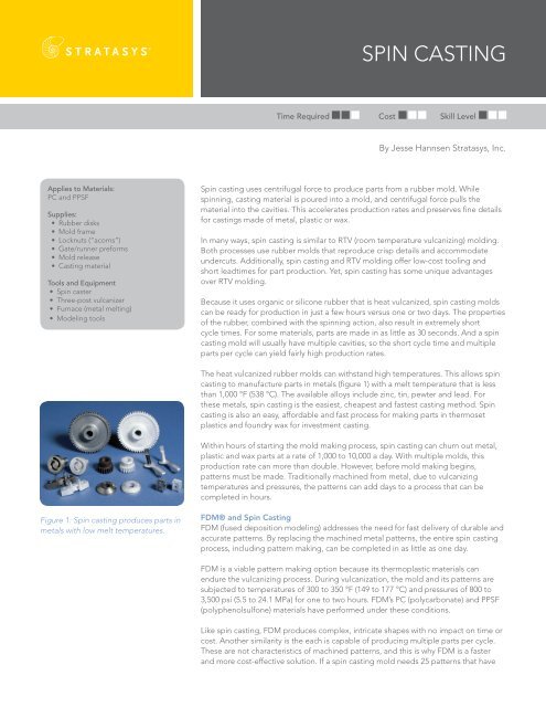
The heat vulcanized rubber molds can withstand high temperatures. This allows spin<br />
casting to manufacture parts in metals (figure 1) with a melt temperature that is less<br />
than 1,000 °F (538 °C). The available alloys include zinc, tin, pewter and lead. For<br />
these metals, spin casting is the easiest, cheapest and fastest casting method. Spin<br />
casting is also an easy, affordable and fast process for making parts in thermoset<br />
plastics and foundry wax for investment casting.<br />
Within hours of starting the mold making process, spin casting can churn out metal,<br />
plastic and wax parts at a rate of 1,000 to 10,000 a day. With multiple molds, this<br />
production rate can more than double. However, before mold making begins,<br />
patterns must be made. Traditionally machined from metal, due to vulcanizing<br />
temperatures and pressures, the patterns can add days to a process that can be<br />
completed in hours.<br />
Figure 1: Spin casting produces parts in<br />
metals with low melt temperatures.<br />
FDM® and Spin Casting<br />
FDM (fused deposition modeling) addresses the need for fast delivery of durable and<br />
accurate patterns. By replacing the machined metal patterns, the entire spin casting<br />
process, including pattern making, can be completed in as little as one day.<br />
FDM is a viable pattern making option because its thermoplastic materials can<br />
endure the vulcanizing process. During vulcanization, the mold and its patterns are<br />
subjected to temperatures of 300 to 350 °F (149 to 177 °C) and pressures of 800 to<br />
3,500 psi (5.5 to 24.1 MPa) for one to two hours. FDM’s PC (polycarbonate) and PPSF<br />
(polyphenolsulfone) materials have performed under these conditions.<br />
Like spin casting, FDM produces complex, intricate shapes with no impact on time or<br />
cost. Another similarity is the each is capable of producing multiple parts per cycle.<br />
These are not characteristics of machined patterns, and this is why FDM is a faster<br />
and more cost-effective solution. If a spin casting mold needs 25 patterns that have
numerous features, including undercuts, an FDM machine can easily produce them<br />
in only a few hours. Another advantage of FDM that is not true of machining or spin<br />
casting is that the production process is laborless and automated. While casting parts<br />
from one mold, the FDM machine can be working in the background making patterns<br />
for the next project.<br />
With FDM, spin casting can produce thousands of metal, plastic or wax parts in a<br />
single day<br />
Process Overview<br />
Molds are formed by placing patterns between disks of uncured rubber. The mold is<br />
then loaded into a vulcanizer that applies heat and pressure to cure the rubber. After<br />
a few hours, the mold becomes firm yet flexible.<br />
The mold is then loaded into a spin casting machine. After the spin cycle starts, the<br />
liquid metal, plastic or wax is poured into the rotating mold. Pressure caused by<br />
centrifugal force pushes the liquid through the mold’s runner system, completely<br />
filling each mold cavity (figure 2). After the material has solidified, the mold is<br />
removed, and the castings are extracted.<br />
Figure 2: Metal, plastic or wax<br />
is poured into a rotating mold.<br />
Centrifugal force pushes the material<br />
into the mold cavities.<br />
Process<br />
A spin casting project begins with a mold layout and selection of pattern material.<br />
The layout of a spin casting mold will usually consist of multiple parts that are placed<br />
symmetrically around the center hub. A mold may be designed to create many copies<br />
of the same part or many different parts. This layout will determine the number of<br />
FDM patterns required.<br />
Of all the FDM materials, PC (polycarbonate) and PPSF (polyphenolsulfone) are the<br />
best suited for pattern making. Due to the temperature and pressure applied to the<br />
mold during vulcanization, patterns constructed in other FDM materials may warp<br />
and distort.<br />
The FDM Process<br />
FDM® (fused deposition modeling) is<br />
a direct digital manufacturing process<br />
patented by Stratasys, Inc. The FDM<br />
process creates functional prototypes,<br />
tooling and manufactured goods from<br />
engineering thermoplastics, such as ABS,<br />
sulfones and polycarbonate, as well as<br />
medical versions of these plastics.<br />
FDM machines dispense two<br />
materials—one for the model and one<br />
for a disposable support structure. The<br />
material is supplied from a roll of plastic<br />
filament on a spool or in a cartridge. To<br />
construct the model, the filament is fed<br />
into an extrusion head and heated to a<br />
semi-liquid state. The head then extrudes<br />
the material and deposits it in layers as<br />
fine as 0.005 inch (0.127 mm) thick.<br />
Unlike some additive fabrication<br />
processes, FDM requires no special<br />
facilities or ventilation and involves no<br />
harmful chemicals and byproducts.<br />
In general, PPSF will produce the most accurate spin cast parts because of its high<br />
heat deflection temperature and mechanical strength. However, it also requires<br />
more time and labor for support removal and pattern preparation. PC is more easily<br />
finished, but it is slightly less stable in the vulcanizing process, which may translate to<br />
larger dimensional deviations.<br />
Pattern Making<br />
FDM patterns can be made from a casting’s CAD data with no need for modification.<br />
Since the mold is pliable, draft angles do not need to be added to the design and<br />
small undercuts do not need to be removed. Optionally, shrinkage compensation can<br />
be added to the CAD data prior to exporting an STL file, but this can also be done<br />
within Insight.<br />
The shrinkage compensation will vary with the rubber used for the mold and the<br />
material that is cast. Refer to supplier information and calculate the net shrinkage<br />
for the mold and castings. Scale the STL files by this shrinkage amount. In Insight,<br />
orient the patterns for the best surface quality and detail, and then select the solid<br />
build style. Any patterns constructed with sparse fill will be subject to collapse when<br />
exposed to the pressure of the vulcanizer.<br />
After the build is completed, remove the support structures and finish the patterns<br />
to the desired quality level. Since the rubber molds will pick up very small details, it is<br />
import to smooth all surfaces to the quality level needed in the cast parts. To achieve<br />
the desired finish, use a combination of DCM (methylene chloride) dipping (PC only),<br />
sanding, filling and priming.
Mold Making<br />
The spin casting mold begins as pre-formed, uncured rubber disks that have a<br />
consistency similar to modeling clay. The type of rubber—organic or silicone—is<br />
selected based on the material to be cast, type of part and desired production<br />
quantities.<br />
Figure 3: Patterns, center plug and<br />
locknuts are placed on the uncured<br />
rubber disk.<br />
The rubber disks are stacked to the desired thickness for the core side of the mold.<br />
The patterns are then arranged in a balanced, symmetrical pattern to ensure even<br />
material distribution (figure 3). Each pattern is then aligned such that material can be<br />
easily pulled through the cavity. Typically, this orientation has the longest side of the<br />
part along a radial line from the hub.<br />
Once placed and aligned, the patterns are then embedded in the rubber to define<br />
the parting line for the cast part. For flat bottomed parts, the patterns are laid on top<br />
of the rubber. For all others, a shallow pocket is cut into the rubber. The pattern is<br />
then set into the pocket, and the excess rubber is shaped around it to establish the<br />
parting line.<br />
Next, insert a center plug into the middle of the rubber disc to create the sprue. Then<br />
arrange locknuts or pins on the perimeter to ensure proper alignment of the two<br />
mold halves when assembled for casting. Optionally, preforms for the runner system<br />
may also be placed into the mold. The core side of the mold is now complete.<br />
Place the core side in a circular mold frame, and spray the surface with mold release.<br />
To complete the mold, stack additional uncured rubber discs on top of the core side<br />
of the mold. This will be the cavity side of the mold.<br />
Figure 4: The mold is loaded into a<br />
vulcanizer that cures the rubber.<br />
Mold Vulcanizing<br />
The vulcanizer consists of two heated platens mounted on a hydraulic press. The<br />
heat and pressure of the vulcanizer cause the uncured rubber to flow around the<br />
patterns and fill the voids. As the exposure to elevated temperatures continues, the<br />
rubber begins to cure, which causes it to become firm yet flexible.<br />
The uncured rubber mold containing the patterns is placed into the vulcanizer<br />
(figure 4), which is preheated to 315 °F (157 °C). The pressure is then slowly raised to<br />
approximately 1,000 psi (6.9 MPa) to squeeze the halves of the mold. The pressure<br />
and temperature, which vary by type of rubber, are maintained for one to two hours.<br />
When vulcanizing is complete, the mold is removed. After a short cooling period,<br />
the mold frame is taken off, and the two halves are separated. The patterns, and any<br />
metal preforms, are then extracted from the mold.<br />
Figure 5: Gates, runners and vents are<br />
cut into the rubber mold with a sharp<br />
knife or scalpel.<br />
Gates, runners and vents are now cut into the cured rubber (figure 5) with a sharp<br />
knife or scalpel. Typically, each is a V-shaped channel. The gates and runners feed<br />
casting material to the part cavity from the central hub. The vent allows air in the<br />
cavity to escape so that backpressure does not cause a partial fill of the mold cavity.<br />
The mold is now ready for spin casting.<br />
Casting<br />
Apply mold release to both sides of the rubber mold, close the mold and place it in<br />
the spin casting machine (figure 6).<br />
Figure 6: The mold is loaded into the<br />
spin casting machine.<br />
Prior to starting the spin casting machine, prepare the casting material. If casting<br />
metal, melt the material in a gas or electric furnace. Bring the molten alloy to the<br />
ideal casting temperature. If the metal is too cold, it will freeze off before filling the<br />
mold, and if too hot, it will degrade the mold prematurely. When casting foundry wax,<br />
melt the material in a suitable melting tank or pot. For thermoset materials, combine<br />
the two parts of the material kit and stir thoroughly.
To prepare the spin caster, select the rotational speed, clamping pressure and cycle<br />
time. Each variable will be dependent on the material that is cast. For example,<br />
metals will have a cycle time of less than one minute, while plastics will have a<br />
duration of five to 10 minutes.<br />
Start the spin caster, and as the mold is spinning, pour the casting material into the<br />
funnel at the top of the machine (figure 7). When the cycle is complete, remove the<br />
mold from the spin caster.<br />
Figure 7: While spinning, molten metal<br />
is poured into the mold.<br />
Finishing<br />
Separate the two halve of the rubber mold to expose the castings (figure 8). To<br />
extract them, flex the rubber or gently pry the casting from its cavity. If any material<br />
remains in the gate, runner or vent channels, remove it prior to reusing the mold.<br />
Finish the casting by snapping the gates off of the part and grinding or sanding the<br />
remainder. The castings are now ready for painting, plating or use.<br />
Conclusion<br />
For metal, plastic and wax parts, spin casting is a simple, affordable and fast method<br />
for prototyping or production. With FDM, the same can be said of the pattern-making<br />
process. Within hours, molds can be made and parts can be cast.<br />
Suppliers<br />
Tekcast Industries, Inc. (www.tekcast.com)<br />
Figure 8: After the metal has cooled,<br />
separate the mold to expose the castings.<br />
More Information<br />
For additional information on carbon fiber composites with FDM, or assistance with<br />
process selection and implementation, contact Stratasys’ application consulting team<br />
at (952) 937-3000 or visit www.stratasys.com.<br />
All images courtesy of Tekcast Industries, Inc.<br />
For more information about Stratasys systems and materials, contact your representative at +1 888.480.3548 or visit www.stratasys.com<br />
Stratasys Inc.<br />
7665 Commerce Way<br />
Eden Prairie, MN 55344-2080<br />
+1 888 480 3548 (US Toll Free)<br />
+1 952 937 3000<br />
+1 952 937 0070 (Fax)<br />
www.stratasys.com<br />
info@stratasys.com<br />
Stratasys GmbH<br />
Weismüllerstrasse 27<br />
60314 Frankfurt am Main<br />
Germany<br />
+49 69 420 9943 0 (Tel)<br />
+49 69 420 9943 33 (Fax)<br />
europe@stratasys.com<br />
©2008 Stratasys Inc. All rights reserved. Stratasys and FDM are registered trademarks and Real Parts, FDM 200mc, FDM 360mc, FDM<br />
400mc, and FDM 900mc are trademarks of Stratasys Inc., registered in the United States and other countries. All other trademarks<br />
are the property of their respective owners . Product specifications subject to change without notice.<br />
Printed in the USA. APXX 01/08

