SIX-PORT MEASUREMENT TECHNIQUE ... - S-TEAM Lab
SIX-PORT MEASUREMENT TECHNIQUE ... - S-TEAM Lab
SIX-PORT MEASUREMENT TECHNIQUE ... - S-TEAM Lab

You also want an ePaper? Increase the reach of your titles
YUMPU automatically turns print PDFs into web optimized ePapers that Google loves.
<strong>SIX</strong>-<strong>PORT</strong> <strong>MEASUREMENT</strong> <strong>TECHNIQUE</strong>: PRINCIPLES,<br />
IMPACT, APPLICATIONS<br />
Vladimir Bilik<br />
Slovak University of Technology, Faculty of Electrical Engineering and Information Technology,<br />
Ilkovicova 3, SK-81219 Bratislava, Slovakia. E-mail: bilikv@elf.stuba.sk<br />
1. Summary<br />
The paper reviews the development of the six-port measurement technique since the time it was<br />
introduced in 1977 until present days. Working principles of six-port reflectometer and six-port network<br />
analyzer are explained. The technique is put in context with other scattering parameter measurement<br />
principles; the advantages and drawbacks are discussed. Some typical SPR implementations are<br />
presented. Basic six-port calibration methods are outlined; general significance of TRL method is<br />
accented. Accomplishments achieved in the Department of Radio and Electronics of FEEIT STU<br />
Bratislava are presented. Current standing of the technique is assessed.<br />
2. Introduction<br />
The official birthyear of the six-port measurement technique is 1977, when three fundamental papers [ 1 ]<br />
– [ 3 ] and several accompanying papers were published in the December issue of the IEEE Transactions<br />
on Microwave Theory and Techniques. Although the inventors, Glenn F. Engen and Cletus A. Hoer of<br />
the National Bureau of Standards (now National Institute of Standards and Technology), Boulder,<br />
Colorado, USA, had published papers with partial ideas and used the term previously, these articles<br />
presented for the first time a complete and unified theoretical background and offered guidelines for<br />
optimum six-port design.<br />
The six-port technique is a method of network analysis, i.e. that of scattering parameters measurement:<br />
either only of reflection coefficient, in which case we speak about six-port reflectometer (SPR) or both<br />
reflection and transmission coefficients, in which case we speak about six-port network analyzer (SPNA).<br />
Although the principle of SPNA will be explained, this paper concentrates on six-port reflectometers.<br />
3. Scattering Parameters<br />
While in low-frequency applications the signals we are concerned with are voltages and currents, in RF<br />
and almost exclusively in microwave applications the signals are described by wave variables, linked<br />
with physical waves traveling along transmission lines (Fig. 1). For waves traveling toward a device<br />
under consideration (incident waves) these variables are denoted a; for waves traveling outward<br />
(transmitted and reflected waves) these variables are denoted b.<br />
a 1<br />
b 1<br />
Ref. plane 1<br />
1<br />
Circuit<br />
1<br />
2<br />
Fig. 1: A microwave circuit (2-port)<br />
Ref. plane 2<br />
Magnitude of a wave variable is derived from mean power P carried by the corresponding physical<br />
wave:<br />
b 2<br />
a 2
a =<br />
P<br />
This is because P is an unambiguous quantity while, apart from TEM waves (propagating e.g. in coaxial<br />
lines), voltage and current cannot be uniquely defined in microwave circuits.<br />
Phase. A wave variable must be related to a certain plane perpendicular to the direction of propagation<br />
(reference plane). The phase of a wave variable is then equal to that of the corresponding physical wave at<br />
that plane (e.g. of the electric field strength).<br />
In cases where voltage can be unambiguously defined (e.g. in lumped-element circuits or in transmission<br />
lines with TEM waves) there is the following relation between the voltage and wave variable:<br />
a =<br />
V<br />
2Z 0<br />
V is the voltage phasor (complex amplitude) of an individual wave at a given plane and Z0 is chosen real<br />
reference impedance (e.g. the characteristic impedance of the transmission line).<br />
a1<br />
b1<br />
b2<br />
1<br />
2<br />
bn<br />
n<br />
loss<br />
3<br />
2<br />
bn-1<br />
b3<br />
n-1<br />
Fig. 2: Distribution (scattering) of incident wave a 1 in a microwave circuit<br />
The network under consideration (device under test - DUT) may have one or more (generally n≥1)<br />
input/output ports (Fig. 2). A reference plane is assigned to each port at which the wave variables are<br />
defined. So, there are n input signals (incident waves) a i , i = 1...n, and n responses b j , j = 1...n. Any<br />
linear n-port is therefore characterized by n 2 transfer functions, relating the responses to the stimuli. The<br />
transfer functions are denoted Sji ( f )and called scattering parameters or S-parameters of the n-port. The<br />
complete relation is given by the matrix equation<br />
( 1 )<br />
⎡b1<br />
⎤ ⎡S<br />
⎢ ⎥ ⎢<br />
⎢<br />
b2<br />
⎥ ⎢<br />
S<br />
⎢ . ⎥ = ⎢ .<br />
⎢ ⎥ ⎢<br />
⎢ . ⎥ ⎢ .<br />
⎢<br />
⎣b<br />
⎥<br />
⎦<br />
⎢<br />
n ⎣S<br />
n<br />
11<br />
21<br />
1<br />
S<br />
S<br />
S<br />
12<br />
22<br />
.<br />
.<br />
n2<br />
.<br />
.<br />
.<br />
.<br />
.<br />
.<br />
.<br />
.<br />
.<br />
.<br />
S<br />
S<br />
S<br />
1n<br />
2n<br />
.<br />
.<br />
nn<br />
⎤ ⎡a1<br />
⎤<br />
⎥ ⎢ ⎥<br />
⎥ ⎢<br />
a2<br />
⎥<br />
⎥ × ⎢ . ⎥<br />
⎥ ⎢ ⎥<br />
⎥ ⎢ . ⎥<br />
⎥<br />
⎦<br />
⎢<br />
⎣a<br />
⎥<br />
n ⎦<br />
k<br />
bk
The S-parameters can be classified as<br />
• reflection coefficients Γ i = Sii<br />
, when the response is a wave traveling out of DUT in the same port as<br />
the stimulus (reflected wave), or<br />
• transmission coefficients t ji<br />
port.<br />
= S ji , j≠i, when the response is a wave traveling out of DUT in another<br />
4. Network Analyzers<br />
The network analyzer (NA) is an instrument to measure scattering parameters. Two distinct measurement<br />
principles can be differentiated:<br />
• Wave separation method (conventional NA)<br />
• Interference method (slotted line, six-ports)<br />
Wave Separation Method<br />
This is conceptually straightforward, definition-based measurement. Practically all commercially<br />
available NA work on this principle. A single stimulus (incident wave) is injected into one of the ports<br />
and the responses at all ports are observed and compared with the stimulus.<br />
For the measurement of reflection coefficient, the incident and reflected waves must be somehow<br />
separated since they appear at the same port. Directional couplers or directional bridges (Wheatstone<br />
bridges) are used for this purpose.<br />
To arrive at a scattering parameter, we must compute<br />
• the ratio of amplitudes<br />
• the phase difference<br />
of the corresponding response and the stimulus. Obtaining the phase difference is a major complication.<br />
Heterodyne dual-conversion receivers phase-locked to the stimulus are employed for this purpose.<br />
The principal block diagram of a conventional NA is in Fig. 3 where DUT (device under test) is the<br />
object being measured.<br />
G<br />
Display<br />
a 1<br />
Processing<br />
Unit<br />
b 1<br />
b 2<br />
3<br />
DUT<br />
1 2<br />
Fig. 3: Conventional, wave separation-based network analyzer<br />
Interference Method<br />
The interference method does not separate the stimulus from the response. On the contrary, several<br />
controlled linear combinations of the two waves are created in the measurement system, and the resulting<br />
amplitudes are observed. Using these amplitude-only data, both modulus and phase of scattering
parameters can be obtained. Six-port method belongs to this category. The required number of wave<br />
combinations is optimally three plus a sample where the stimulus prevails (reference signal).<br />
The wave combinations can be<br />
• made and observed simultaneously at various points (ports) of the measurement system, or<br />
• created and observed sequentially at the same port (multistate or switched systems). The slotted line<br />
is an example of such a system; here the incident and reflected wave are combined along the line,<br />
giving rise to standing wave pattern (Fig. 4).<br />
Care must be taken with the multistate systems because certain conditions must be satisfied for their<br />
applicability. Loosely speaking, the external circuits must not notice there is something happening inside<br />
the system when the state is changing (switching, moving a probe).<br />
GEN<br />
V<br />
60 o<br />
V<br />
Max Min<br />
Fig. 4: Slotted line<br />
4<br />
a<br />
b<br />
θ<br />
DUT<br />
Γ Γ = a / b<br />
The question now may be raised: Is then the slotted line a SPR? The answer is: What makes a device SPR<br />
is not only its hardware implementation but also the way the measured data are processed. If the<br />
mathematics of SPR is applied to voltages obtained from the detector of a slotted line probe (taken e.g. at<br />
the positions designated by the red circles), then the answer may be yes.
In SPNA, the interference principle is even more noticeable: the stimuli are applied at both ports of DUT<br />
simultaneously.<br />
5. Six-Port Reflectometer<br />
a 6<br />
GEN 6<br />
b 6<br />
b 2<br />
b 3<br />
D2<br />
3<br />
a 2<br />
a 3<br />
5<br />
b 1<br />
<strong>SIX</strong> - <strong>PORT</strong><br />
b 4<br />
D1<br />
2 1<br />
D3<br />
REF<br />
4<br />
D4<br />
a 1<br />
a 4<br />
5<br />
b 5 =b<br />
a 5 =a<br />
Γ<br />
DUT<br />
= a/b<br />
Fig. 5: Principal block diagram of six-port reflectometer<br />
The basic building block of the SPR is a linear six-port (Fig. 5), one port of which is terminated in a<br />
device under test (DUT), one port is connected to the signal source (GEN), and the remaining four ports<br />
are connected to power detectors (D1 – D4). DUT is characterized by the reflection coefficient Γ. The<br />
state of the six-port is determined by 12 complex wave variables ai , bi<br />
, i = 1...<br />
6 . The variables are not<br />
independent: they are mutually coupled by scattering parameters of the six-port, i.e. by six equations<br />
incorporated in ( 1 ). Moreover, since the detector ports are terminated in defined (although not inevitably<br />
known) loads – detectors, additional four restraints are added of the form<br />
( 2 ) ai = ΓDi<br />
bi<br />
i = 1...<br />
4<br />
where Γ Di is reflection coefficient of i-th detector. Hence, there are ten constraints for the twelve<br />
variables i i b a , . The system has therefore only two degrees of freedom. This means that only two of the<br />
waves can be chosen arbitrarily; the rest can be expressed as linear combinations (superpositions) of the<br />
two. For sake of SPR theory, it is useful to choose the wave 5 b b ≡ incident on DUT and the wave<br />
a ≡ a5<br />
= Γb<br />
reflected from DUT as the independent variables. The waves incident on the detectors can<br />
then be expressed as<br />
⎛ a B ⎞ i<br />
( 3 ) b ⎜<br />
⎟<br />
i = Aia<br />
+ Bib<br />
= bAi<br />
+ = bAi<br />
( Γ − qi<br />
) i = 1...<br />
4<br />
⎝ b Ai<br />
⎠<br />
where i i B A , are complex quantities characterizing SPR (they depend only on S-parameters of the six-port<br />
and reflection coefficients of the detectors),
Γ = a / b<br />
is the sought reflection coefficient of the DUT, and the complex numbers<br />
( 4 ) qi = − Bi<br />
Ai<br />
are termed q-points of the SPR. Detector outputs are supposed to be proportional to input RF powers:<br />
( 5 )<br />
2<br />
i<br />
i<br />
2<br />
P = b = A a + B b = P A Γ − q<br />
i<br />
i<br />
2<br />
0<br />
i<br />
2<br />
Here P 0 = b is the power incident on DUT (in many cases also of metrologist’s interest). One of the<br />
detectors, called reference detector (here denoted as D4) should ideally, although not necessarily, respond<br />
only to wave b, incident on the DUT: this would lead to q4 approaching infinity. It is therefore more<br />
appropriate for the reference detector to write ( 5 ) in an alternative form<br />
( 6 )<br />
P<br />
where 4 4<br />
4<br />
4<br />
0<br />
2<br />
4<br />
= P B dΓ<br />
+ 1<br />
d = A B = −1<br />
q . For an ideal reference port, d = 0.<br />
Introducing normalized powers 4 P P pi = i , one can write<br />
( 7 )<br />
Pi<br />
Γ − qi<br />
pi<br />
= = Ci<br />
i = 1...<br />
3<br />
P dΓ<br />
+ 1<br />
2<br />
4<br />
2<br />
2<br />
where Ci = Ai<br />
B4<br />
. The three equations ( 7 ) are often called the working equations of the six-port<br />
reflectometer. They relate reflection coefficient Γ of DUT to measured quantities – detector powers. As<br />
seen, SPR is fully characterized by 11 parameters: four complex quantities (qi, d) and three real scaling<br />
factors Ci (note that the parameters are frequency-dependent). These or other derived set of 11<br />
parameters are called calibration constants. They can be obtained in the process of six-port calibration, in<br />
which a set of known loads (calibration standards) are connected in place of DUT and the detector<br />
responses are recorded. To arrive at the calibration constants from such data may be quite a formidable<br />
task. Once the calibration constants are known, the measurement consists in<br />
• connecting DUT<br />
• measuring detector powers<br />
• solving three simultaneous nonlinear equations ( 7 ) for the unknown Γ.<br />
Graphically, each of the equations represents a circle in the Γ-plane (often called a q-circle). The situation<br />
is best illustrated for the case of an ideal reference port (d = 0), when the equations ( 7 ) simplify to<br />
( 8 ) = C Γ − q i = 1...<br />
3<br />
pi i i<br />
2<br />
and represent circles with centers qi and radii r i = pi<br />
Ci<br />
, the radii being proportional to the square<br />
root of detector powers. Each circle represents a set of possible values of Γ satisfying the particular<br />
equation. The sought solution must be the common intersection of the three circles (Fig. 6). The shaded<br />
area (unit circle) corresponds to all passive loads.<br />
6<br />
2<br />
i
a 23<br />
r 2<br />
q 2<br />
r 3<br />
a 12<br />
Γ<br />
j Im<br />
q 3<br />
7<br />
q 1<br />
Re<br />
r 1<br />
a 31<br />
Fig. 6: Graphical solution of the six-port equations for the unknown Γ<br />
It is evident that the q-points are essential SPR parameters since reflection coefficient can be accurately<br />
obtained only when q-points are properly positioned.<br />
Note that the system is overdetermined, i.e. one of the three circles only decides between two possible<br />
intersections obtained from the other two circles. This redundancy inherent in SPR technique adds to<br />
measurement accuracy and helps detect any inconsistencies.<br />
In the general case (d ≠ 0) the three-circle interpretation still holds, only the formulas for the centers and<br />
radii are more complex.<br />
Analytically, the solution Γ is usually sought as the intersection of the three common cords a12, a23, and<br />
a31 (any two of them are sufficient). This leads to the simple formula<br />
c1P1<br />
+ c2P2<br />
+ c3P3<br />
+ c4P4<br />
s1P1<br />
+ s2P2<br />
+ s3P3<br />
+ s4P4<br />
Γ =<br />
+ j<br />
m1P1<br />
+ m2P2<br />
+ m3P3<br />
+ P4<br />
m1P1<br />
+ m2P2<br />
+ m3P3<br />
+ P4<br />
or, in terms of normalized powers,<br />
c1<br />
p1<br />
+ c2<br />
p2<br />
+ c3<br />
p3<br />
+ c4<br />
s1<br />
p1<br />
+ s2<br />
p2<br />
+ s3<br />
p3<br />
+ s4<br />
( 9 ) Γ =<br />
+ j<br />
m p + m p + m p + m p + m p + m p + 1<br />
1<br />
1<br />
2<br />
2<br />
3<br />
3<br />
1 1 1 2 2 3 3
where the 11 real parameters c1...c4 , s1...s4 , and m1...m3 are another form of calibration constants; they<br />
can be expressed in terms of qi, d, Ci . Equation ( 9 ) gives a reasonable solution (Fig. 7) also for the<br />
practical case of the circles not intersecting in a single point (even for the circles not intersecting at all).<br />
Fig. 7: Solution using chords for circles not intersecting in a single point<br />
Power Measurement<br />
A special potential of SPR is its capability also to measure incident power P0. This is enabled by Eq. ( 6 ),<br />
which can be converted to<br />
( 10 ) P = K m P + m P + m P + P ) = KP ( m p + m p + m p + 1)<br />
0<br />
( 1 1 2 2 3 3 4 4 1 1 2 2 3 3<br />
where mi are the same as in ( 9 ). An additional constant K must be obtained by an extra calibration step<br />
consisting in incident power measurement with an arbitrary load (e.g. a thermistor mount) in place of<br />
DUT.<br />
Knowing P0 and Γ, also the reflected power Pr and the power Pa absorbed in load (an antenna or a<br />
chicken in a microwave oven) can be computed:<br />
2<br />
0 Γ = P P 2<br />
r Pa = P0<br />
− Pr<br />
= P0<br />
( 1− Γ )<br />
Optimum SPR<br />
An optimum SPR is one that is the least sensitive to detector power measurement error. The outlined<br />
graphical interpretation of working equations indicates that this is closely linked with q-point positions.<br />
Intuitively:<br />
• The best case appears when the q-points are arranged symmetrically around the reflection coefficient<br />
to be measured.<br />
• A fatal situation occurs when two q-points coincide or when all are centered on a single line; this<br />
results in two indistinguishable solutions (Fig. 8).<br />
• An ill-conditioned, although not fatal, case occurs when Γ is very close to a q-point. This is because<br />
in such case the detector power Pi approaches zero and the q-circle radius is in fact determined<br />
merely by noise fluctuations. The same noise level less affects greater radii.<br />
• An unfavorable case also occurs for reflection coefficients on a line connecting two circle centers<br />
where q-circles do not intersect but only touch. This results in excessive sensitivity to circle radii<br />
variations (Fig. 9).<br />
The criteria for an optimum SPR can then be summed up as follows:<br />
8
1. Reference detector should respond to the wave incident on DUT.<br />
2. Phases of q-points should differ by 120 ο .<br />
3. Magnitudes of q-points should be approximately 2.<br />
The latter two criteria can also be formulated such that the q-points are vertices of an equilateral triangle<br />
touching or encompassing the unit circle (Fig. 10).<br />
SPR design then consists in determining the q-points of a given structure and trying to approximate the<br />
above criteria in as wide a frequency range as possible or required.<br />
Fig. 8: Fatal situation: all Q-circle centers in-line<br />
Fig. 9: Touching Q-circles: high sensitivity to power measurement error<br />
9<br />
?<br />
?
q 1<br />
6. Dual Six-Port Network Analyzer<br />
10<br />
+j<br />
0 1<br />
q 2<br />
q 3<br />
Fig. 10: An optimum q-point distribution<br />
Two six-port reflectometers can be used in the configuration shown in Fig. 11 to measure all Sparameters<br />
of any linear two-port [ 3 ]. Such arrangement is usually called dual six-port network<br />
analyzer. A six-port reflectometer (SPR1, SPR2) is connected to each port of the DUT. Both<br />
reflectometers are simultaneously fed from the same signal source using a power divider PD. The<br />
complex ratio a2/a1 of the input waves can be varied by means of the attenuator AT cascaded with the<br />
phase shifter PS. The waves ai, bi are interrelated by the scattering equations<br />
b = S a + S<br />
1<br />
11<br />
1<br />
12<br />
b = S a + S<br />
2<br />
21<br />
1<br />
where Sij are the sought scattering parameters of DUT.<br />
22<br />
a<br />
2<br />
a<br />
2<br />
+
3<br />
GEN<br />
PD<br />
11<br />
AT PS<br />
DUT<br />
1<br />
2<br />
SPR1 1 2<br />
SPR2<br />
SPR1 and SPR2 measure the complex ratios<br />
b1<br />
a2<br />
Γ 1 = = S11<br />
+ S12<br />
a a<br />
1<br />
S ij<br />
a 1 b 1 b 2 a 2<br />
Fig. 11: Dual six-port network analyzer<br />
1<br />
b2<br />
a1<br />
Γ 2 = = S22<br />
+ S21<br />
a2<br />
a2<br />
respectively. Eliminating the ratio a2/a1 leads to the equation<br />
( 11 ) Γ2S 11 + Γ1S<br />
22 − D = Γ1Γ2<br />
for three unknowns: S 11, S22<br />
and the determinant D = S11S<br />
22 − S12S<br />
21 . The unknowns can be obtained by<br />
solving a simultaneous set of at least three equations ( 11 ). The equations are generated by various<br />
settings of the phase shifter PS and attenuator AT. The settings need be neither known nor reproducible:<br />
they do not enter into the equations. If the DUT is known to be reciprocal, S 12 = S21<br />
can be expressed<br />
from D, hence the task is completed. If the DUT is not known to be reciprocal, some more work is to be<br />
done: three different reciprocal two-ports with approximately known a2/a1 ratio must be measured to<br />
calibrate the same three settings of the AT+PS combination. The two-ports can be two transmission line<br />
sections with approximately known lengths and a “thru”-device: direct connection of SPR1 and SPR2.<br />
Imperfect repeatability of the AT+PS settings affects only phases of S 12 and S 21.<br />
7. Calibration<br />
Calibration is the process of obtaining the 11 calibration constants of a SPR in whatever form they may<br />
be expressed. A considerable effort has been devoted to the development of calibration procedures. Some<br />
methods (notably TRL and its LRL modification) are applicable also to conventional network analyzers.
In the process of calibration, a set of terminations are connected in place of DUT and the corresponding<br />
detector powers are recorded. The terminations may be known (calibration standards) or unknown<br />
(auxiliary loads). The detector powers and reflection coefficients of the terminations are substituted to the<br />
SPR working equations ( 7 ). The obtained set of equations is solved for the unknown calibration<br />
constants (reflection coefficients of the unknown loads are obtained as a by-product).<br />
The calibration loads can be classified as follows:<br />
1. Fully known loads (calibration or impedance standards). Their reflection coefficients enter SPR<br />
equations as known quantities. Their knowledge is therefore critical since it directly affects the<br />
accuracy with which the calibration constants are obtained hence the resulting SPR measurement<br />
accuracy. Generally, there is an effort to develop calibration methods which use use as few standards<br />
as possible.<br />
2. Unknown loads. Their parameters enter SPR equations as unknown quantities hence do not affect<br />
SPR measurement accuracy. Each such load adds two new unknowns (the real and imaginary parts of<br />
its reflection coefficient) but generates three equations ( 7 ), hence the net gain is one. The unknown<br />
loads therefore reduce number of required standards. The loads can be unknown yet not arbitrary:<br />
they must be chosen such that the generated equations are independent (e.g. the same equations are<br />
generated by a short circuit and a shorted transmission line half-wavelength long).<br />
3. Partially known loads. They serve in principle as unknown loads but the approximate knowledge of<br />
some of their parameters (e.g. reflection coefficient, length) helps decide between more<br />
mathematically possible solutions. They may also serve for finding an approximate solution used as<br />
first guess in numerical procedures.<br />
4. Sliding loads. The property is exploited that when the load is slid the reflection coefficient moves<br />
along a circle in the Γ-plane. It usually leads to complicated mathematical procedures.<br />
Fig. 12: X-band waveguide calibration standards<br />
Typical calibration loads are<br />
• Matched (non-reflecting) termination (fixed or sliding); often used as a standard<br />
• Sections of transmission lines (shorted or open); often used as standards<br />
• Attenuators terminated by the above sections of transmission lines<br />
• Capacitors or inductors (for lower frequencies)<br />
An example of waveguide calibration set (8.2 – 12.4 GHz) consisting of a sliding matched load and four<br />
offset shorts is shown in Fig. 12.<br />
12
The mathematics of calibration is simpler when more known standards are employed. However, the<br />
accuracy suffers since it depends on uncertainties of the many standards. First calibration methods, e.g. [<br />
4 ], used as many as 7 standards. An extra inconvenience of using many loads is a limited frequency<br />
range.<br />
Other six-port calibration methods have been developed that use only four standards, e.g. offset shorts [ 5<br />
], [ 6 ]. Benefit of using a fixed or sliding matched termination as 5th standard may be improved accuracy<br />
of small reflection coefficient measurements [ 7 ]. We have also contributed to these methods ([ 8 ] – [ 10<br />
]); we use them to obtain initial guess for the procedure outlined next.<br />
Six-Port To Four-Port Reduction<br />
Perhaps the most ingenious method has been developed in 1978 by Engen [ 11 ]. It is mathematically a<br />
two-step procedure. The first step is known as six-port to four-port reduction, the second step is<br />
calibration of the equivalent four-port.<br />
The first step uses the fact that the system is overdetermined: i.e. one of the three normalized powers only<br />
decides between two possible solutions obtained from the other two normalized powers. Consequently,<br />
the normalized powers are not independent: they are subject to a constraining relation<br />
( 12 ) F ( p p , p , a,<br />
b,<br />
c,<br />
, ) = 0<br />
1 , 2 3<br />
ζ<br />
ρ<br />
containing five out of the 11 SPR calibration constants (here denoted a , b,<br />
c,<br />
ζ , ρ ). The constants can be<br />
obtained by solving a set of at least 5 simultaneous equations ( 12 ), which can be generated by measuring<br />
pi for at least 5 arbitrary unknown loads 1 . The equations are nonlinear, hence a numerical iteration must<br />
be employed and a good initial solution must be available. The initial solution can be obtained by one of<br />
the above-mentioned methods using the same loads, treating them in this case as known standards.<br />
Having these constants, a complex ratio w = b1<br />
/ b4<br />
can be computed for DUT connected to SPR:<br />
w = G p p , p , a,<br />
b,<br />
c,<br />
ζ , ρ<br />
1,<br />
2 3<br />
( 13 ) ( )<br />
This ratio is linked with the true reflection coefficient Γ of DUT via the formula<br />
EtΓ<br />
( 14 ) w = Ed<br />
+<br />
1−<br />
EmΓ<br />
The complex quantities Ed, Et, Em, represent the remaining 6 calibration constants. When known, the<br />
sought Γ can be computed from the inverse of ( 14 ).<br />
Eq. ( 14 ) is formally identical with the relation between the actual and measured reflection coefficients in<br />
conventional 4-port vector reflectometers, when the measurement is biased by the systematic directivity<br />
error Ed, tracking error Et, and test port mismatch error Em. (This is the reason for the first calibration step<br />
to be called six-port to four-port reduction.) Consequently, as the second calibration step, all methods<br />
developed for the calibration of conventional reflectometers (i.e. for determining of Ed, Et, Em) can be<br />
applied. The simplest is the method which uses three standards, e.g. a short (Γ1 = –1), an open (Γ2 = +1),<br />
and a matched termination (Γ3 = 0). Connecting these standards, we measure the values w1, w2 and w3,<br />
respectively. Inserting Γi and wi into ( 14 ) yields three equations, from which the unknowns Ed, Et, Em<br />
can easily be solved. (Actually, these standards need not be connected since they are normally among<br />
those used in the previous calibration step: only the data recorded for them are reused.)<br />
Now, the calibration is complete.<br />
Thru-Reflect-Line Calibration<br />
The Thru-Reflect-Line (TRL) method [ 12 ] serves for complete calibration of dual six-port network<br />
analyzers. It requires connection of only three calibration devices, among them only one standard. The<br />
devices are (Fig. 13)<br />
1<br />
Methods like this which do not need standards (or need only a reduced number of standards) are called<br />
self-calibration methods.<br />
13
• THRU: Direct connection of the two test ports.<br />
• REFLECT: An unknown load with high reflection coefficient, connected successively to SPR1, then<br />
to SPR2.<br />
• LINE: A piece of non-reflecting transmission line, optimally a quarter-wavelength long (90 o ).<br />
1<br />
2<br />
3<br />
4<br />
THRU<br />
REFLECT<br />
LINE<br />
SPR 1 SPR 2<br />
SPR 1<br />
14<br />
90 o<br />
SPR 2<br />
SPR 1 SPR 2<br />
Fig. 13: TRL calibration connections<br />
The only standard required is a length of precision transmission line or waveguide, which is the most<br />
accurate impedance standard available. The only condition imposed on the line is that it be non-reflecting;<br />
only this affects the analyzer’s measurement accuracy. This is why TRL is perhaps the most accurate<br />
calibration method invented.<br />
Mathematically, the calibration consists of two steps:<br />
1. As the first step, a six-port to four-port reduction is performed for the two six-port reflectometers.<br />
This requires no extra loads since the required equations can be generated by various settings of<br />
attenuator – phase shifter combination for the three calibration devices.<br />
2. As the second step, both equivalent four-ports are calibrated. The mathematics of the procedure is too<br />
extensive to be explained here; the reader is referred to [ 12 ].<br />
The second step of TRL calibration can also be applied to conventional network analyzers. In fact, all<br />
high-precision network analyzers use it. In this way TRL profoundly influenced the network analysis in<br />
general and represents perhaps the most significant contribution the six-port technique offered.<br />
LRL (Line-Reflect-Line) calibration method differs from TRL only in that another line section is used<br />
instead of the THRU connection [ 13 ]. This makes the method more practical, especially when the test<br />
port connectors of SPR1 and SPR2 are of the same sex (THRU connection is impossible) or when the<br />
LINE length is too short to be realizable. A difference between the two line lengths should be optimally a<br />
quarter-wavelength.
8. Six-Port Reflectometer Implementations<br />
This section is a gallery of various SPR implementations as well as an overview of the work done by our<br />
research group. There exist many more structures than those presented below: only lack of space forbids<br />
their mentioning.<br />
It is worth bearing in mind in designing various implementations that a SPR structure must provide at<br />
least one phase shift different from 0 o or 180 o , otherwise all q-points would lie on a single line.<br />
SPR with Directional Couplers<br />
These are the “classical” types, suggested by the SPR inventors [ 2 ]. They use 4-port directional couplers<br />
(Fig. 14) and power dividers. An important property of a directional coupler is that, as a response to an<br />
input wave, the wave emerging from the coupled arm is phase-shifted by –90 o with respect to the wave<br />
emerging from the direct arm. This provides the required phase shift different from 0 o or 180 o .<br />
D4<br />
D3<br />
D2<br />
D1<br />
a 1<br />
a 2<br />
REF<br />
1<br />
2<br />
Fig. 14: Wave distribution in a directional coupler<br />
15<br />
3<br />
4<br />
b 3 = A a 1 - jB a 2<br />
b 4 = A a 2 - jB a 1<br />
G<br />
0 1<br />
Fig. 15: Schematic diagram of the X-band waveguide SPR with directional couplers<br />
q 1<br />
+j<br />
q 2<br />
q 3<br />
+<br />
DUT<br />
Fig. 15 and Fig. 16 show the first SPR realized in our laboratory. It was developed for X-band (8.2-12.4<br />
GHz) in 1985. The medium was R-100 rectangular waveguide (22.86 mm x 10.16 mm). The SPR used<br />
precision high-directivity multihole couplers and zero-bias Schottky diode detectors. The theoretical qpoint<br />
distribution, also shown in Fig. 15, reasonably well approximates the optimum. The SPR proved to<br />
be quite accurate: the reflection coefficient measurement uncertainty was found about 0.01. Its main
disadvantages were bulkiness (1.2 m x 0.3 m) and, which was then not recognized, excessive temperature<br />
dependence.<br />
Fig. 16: Realized X-band waveguide SPR with directional couplers<br />
Microstrip SPR with Directional Couplers<br />
To decrease dimensions, a microstrip clone of the waveguide SPR has been developed and tested in 1986<br />
[ 15 ], consisting of only 3-dB Lange couplers and Wilkinson power dividers (Fig. 17).<br />
R<br />
GEN<br />
D1 D2 D3 D4<br />
16<br />
TES T <strong>PORT</strong><br />
Fig. 17: X-band microstrip SPR layout<br />
The SPR was built on a 50 mm x 50 mm alumina substrate. Higher reflections from the microstrip<br />
couplers and power dividers compared to their waveguide counterparts completely corrupted SPR<br />
parameters and made the whole effort fail. The system was nicknamed Rebel alias Reactance Madhouse.<br />
R
Three-Probe Six-Port Reflectometers<br />
The three-probe six-port reflectometers turned out to be very successful and suitable for many practical<br />
applications requiring a medium bandwidth (up to 1 octave). The first type, completed in 1989, was an Xband<br />
waveguide reflectometer nicknamed Wasp [ 16 ]. Its principal diagram is shown in Fig. 18. The SPR<br />
consists of a waveguide section with a directional coupler (DC) feeding the reference detector D4 and<br />
three probes, spaced electrically by 60 o at the center frequency of the required band. The probes respond<br />
equally to the waves travelling in both directions, which results in unit q-point magnitudes. The phase<br />
angle of a q-point is proportional to the distance the wave must travel from the probe to DUT and back to<br />
the probe. Given the 60 o probe spacing, the q-point phases differ by 120 o , which is the optimum case.<br />
With varying frequency, the q-points rotate, each with different speed, until two of them are too close to<br />
each other. This limits the operation bandwidth. Practically, the angular spacing should not drop below<br />
about 40 o .<br />
Fig. 19 shows the photograph of the realized SPR.<br />
GEN<br />
1<br />
2<br />
D4 D3 D2 D1<br />
Reference<br />
port<br />
3<br />
+j<br />
+<br />
1<br />
17<br />
q 3<br />
+j<br />
3<br />
60 o 60 o<br />
f min f center f max<br />
q 2<br />
Fig. 18: Principle of three-probe SPR<br />
2<br />
+<br />
1<br />
3<br />
q 1<br />
P r<br />
P i<br />
+j<br />
a<br />
b<br />
2<br />
DUT<br />
Γ Γ = a / b<br />
+
Fig. 19: Three-probe X-band waveguide SPR<br />
Using two reflectometers of this type, an X-band dual six-port network analyzer was completed and<br />
successfully tested [ 17 ] but the work discontinued in this direction.<br />
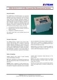
SPR of similar type [ 18 ], named Homer, has been developed for high-power industrial applications at<br />
2.45 GHz, handling powers of up to 30 kW (Fig. 20). The system is an autonomous unit constructed on a<br />
broad wall of R26 waveguide (86.36 mm x 43.18 mm). It contains its own single-board computer and<br />
communicates with external devices via RS232 or CAN bus. Very important for this application is the<br />
power measurement capability of SPR. Because of a free-running magnetron as signal source, the device<br />
must incorporate a frequency counter.<br />
Fig. 20: High-power Homer SPR for industrial applications at 2450 MHz<br />
18
A miniature low-power three-probe SPR implemented as a combination of microstrip and lumpedelement<br />
technology has been developed for the frequency range 2.2 – 2.7 GHz [ 19 ]. The SPR serves for<br />
the purpose of industrial applicators design. The circuit is built on a 35 mm x 35 mm Rogers TMM-6<br />
substrate (εr = 6), using 0805 SMD resistors and capacitors (Fig. 21). The main microstrip line is tapped<br />
by means of resistors at three points separated by approximately 60 o at 2.45 GHz. Resistive coupling has<br />
been chosen for dimensional reasons. In addition, overlapping the edge-coupled directional coupler with<br />
the 3-probe section enabled to reduce the dimensions of the structure by the factor of nearly two. The<br />
length of the coupled section (60 o ) was chosen arbitrarily to conform the physical layout requirements.<br />
The directivity of such shortened coupler could be maximized by varying the impedance terminating the<br />
unused arm (a series RL combination).<br />
Fig. 21: Microstrip three-probe SPR for 2.2 – 2.7 GHz<br />
A similar principle has been used in the high-power SPR [ 20 ] covering the 900 MHz ISM band,<br />
handling CW powers up to 100 kW (Fig. 22, Fig. 23). The transmission medium is the bulky R9<br />
waveguide (247.66 mm x 123.86 mm). A two-probe directional coupler of our own proposal [ 21 ] has<br />
been used to couple signals from the waveguide to a 3-probe microstrip SPR realized on Rogers TMM-10<br />
substrate (εr = 9.3). This enabled to substantially reduce the dimensions of SPR (microstrip probe spacing<br />
is about 20 mm while waveguide probe spacing would be 75 mm).<br />
19
Fig. 22: High-power waveguide SPR for industrial applications at 900 MHz<br />
Fig. 23: Microstrip portion of the SPR<br />
Switched-Reflector Six-Port Reflectometers<br />
The concept of switched-reflector SPR, where the number of detector ports is reduced to one, was<br />
originally conceived at Warsaw Polytechnics [ 22 ]. The principle is that, using switchable phase and<br />
amplitude modulators within the SPR structure, all combinations of the incident and reflected wave<br />
necessary for optimally distributed q-points can be sequentially created at a single detector port. Inspired<br />
by this, we have suggested and both theoretically and experimentally investigated several microstrip<br />
structures, containing two detectors [ 23 ]. An example is shown in Fig. 24. The reflectometer consists of:<br />
• Dual directional coupler (DC1, DC2)<br />
20
• Two detectors (D1, D2)<br />
• Reflection phase modulator (RPM), consisting of three switchable circuits with reflection coefficients<br />
Γi (most simply open-ended microstrip sections with lengths differing by 60 o )<br />
G<br />
D1<br />
21<br />
D2<br />
DC2<br />
DC1<br />
REF<br />
Fig. 24: Two-detector switched SPR<br />
RPM<br />
b<br />
a<br />
60 o<br />
60 o<br />
DUT<br />
D2 is the reference detector sampling the incident wave b. D1 responds to the combination of wave a<br />
reflected from DUT and the wave reflected from RPM. This wave is proportional to b, only its phase<br />
depends on the state of RPM. By switching RPM to its three states, the three required combinations of a<br />
and b are obtained. Magnitudes of q-points depend on the coupling of DC1 and DC2; phase differences of<br />
q-points are equal to phase differences of Γi. One-decade bandwidth can be obtained using broadband<br />
RPM devised by Morawski and Zborowska [ 24 ].<br />
A different type of switched SPR has been suggested at Czech Technical University [ 25 ]. It makes<br />
convenient use of existing scalar network analyzers but connects a multistate circuit, called perturbation<br />
two-port (PTP), between DUT and analyzer’s reflectometer head.<br />
Scalar<br />
Reflectometer<br />
Head<br />
Perturbation<br />
2-port<br />
DUT<br />
Fig. 25: Creating combinations of incident and reflected waves using a perturbation 2-port<br />
Switching between the internal states of the PTP changes its S-parameters, which, if properly designed,<br />
creates the required combinations of the incident and reflected wave at the reflectometer’s detector (Fig.<br />
25). Except one of the states, the perturbation circuit must be partially reflective; this supplies a sample of
the incident wave to the detector. However, the same requirement also causes that, strictly speaking, the<br />
six-port theory does not directly apply.<br />
Another type of the switched SPR will be presented in the section dealing with lumped six-ports.<br />
An advantage of switched six-port reflectometers is their simple construction. The main disadvantages are<br />
reduced speed due to sequential measurement of detector voltages (impossibility to sample pulsed<br />
signals) and tendency to an additional error caused by the fact that SPR theory is not rigorously<br />
applicable.<br />
Dual-Generator Six-Port Reflectometers<br />
The phase shift different than 0 ο and 180 ο that is required for SPR operation can also be realized in a<br />
purely resistive structure if fed from two mutually synchronized, phase-shifted signal sources (Fig. 26).<br />
The case has been theoretically analyzed and experimentally verified with direct digital synthesis (DDS)<br />
generator at frequencies (0 – 10 MHz) [ 26 ]. A feasibility in the range 2 – 27 GHz using a directional<br />
coupler as phasing device has been confirmed by simulation. The idea has then been locked to drawer.<br />
D1 D3<br />
D4<br />
REF<br />
D2<br />
G1 G2<br />
Fig. 26: A dual-generator SPR<br />
22<br />
DUT<br />
q 3<br />
+j<br />
0 1<br />
φ G2 - φ G1 = 90 o<br />
9. Lumped Six-Port Reflectometer<br />
This section is devoted to a special, extremely wideband SPR type which may contain only lumped<br />
elements and, consequently, lends itself to even monolithic integration. While typical bandwidths<br />
achievable by various SPR types range from less than one octave to about 10:1, this type can achieve<br />
bandwidths of up to 1000:1. The structure was invented in 1986. Its core is the Wheatstone bridge [ 27 ], [<br />
28 ]. There is a normal and multistate modification of the SPR. At least one institution (ENST Paris) still<br />
develops the ideas.<br />
Basic circuit diagram of the SPR in its multistate modification is shown in Fig. 27. The device can<br />
conveniently be split into a power divider and a combination circuit.<br />
Power divider provides the reference detector D2 with a sample of incident wave b. Reflected wave a<br />
does not penetrate to the detector because the source of a (DUT) and D2 are in mutually isolated<br />
2<br />
diagonals of a balanced bridge ( Ra Rb<br />
= Z0<br />
).<br />
Provided the bridge is balanced and D2 matched, the reflection coefficient seen at the divider input is<br />
proportional to that of DUT:<br />
2<br />
( 15 ) ΓD<br />
= t Γ<br />
where<br />
Rb<br />
( 16 ) t =<br />
Rb<br />
+ Z0<br />
is transmission coefficient between the divider input and the test port.<br />
q 1<br />
+<br />
q 2
Z0<br />
G<br />
3<br />
2<br />
1<br />
1 2<br />
Γ R<br />
R<br />
D1<br />
R<br />
3 4<br />
Γ D<br />
23<br />
Ra<br />
D2 REF<br />
Combination Circuit Power Divider<br />
Fig. 27: Basic circuit diagram of lumped SPR<br />
Combination circuit provides three linear combinations of the wave incident on and reflected from<br />
DUT; these determine the q-points. The two upper arms (1, 2) of the combination circuit are equal. The<br />
lower left-hand arm (3) serves as reflector: a circuit with high reflection coefficient ΓR, switchable<br />
between three values Γi (i = 1...3) with differing phase angles.<br />
It can be proved (and it is the basic idea behind this SPR type) that the wave incident on detector D1 is a<br />
superposition with the same weight but opposite polarity of the waves reflected from the two lower arms<br />
(3, 4):<br />
2<br />
2⎛<br />
ΓR<br />
⎞<br />
( 17 ) bD<br />
1 = AΓD<br />
− AΓR<br />
= At Γ − AΓR<br />
= At ⎜Γ<br />
− 2 ⎟<br />
⎝ t ⎠<br />
This is actually a six-port equation yielding the q-point<br />
( 18 )<br />
q R Γ =<br />
2<br />
t<br />
Its phase angle is equal to that of the reflector; its magnitude can be controlled by the transmission<br />
coefficient t of the power divider.<br />
One obvious method of making the three necessary wave combinations is a sequential switching of three<br />
different reflectors, as shown in Fig. 27. Such a SPR has been constructed and tested, operating<br />
satisfactorily in 1 to 700 MHz frequency range.<br />
A different combination circuit has been conceived, avoiding the need of switching (Fig. 28). Essentially,<br />
it is a three-fold bridge with tripled left-hand pair of arms (each arm containing one reflector), and three<br />
associated detectors. The mutual cross-coupling between the reflectors and non-associated detectors is<br />
eliminated by introducing the compensation impedances Zc, equal to the detector impedances. Such a<br />
combination circuit is actually a highly symmetrical structure as shown by its redrawing in Fig. 29. The<br />
formula ( 18 ) for q-points remains valid.<br />
Being a resistive structure, the SPR has a potential to be very broadband. The ultimate bandwidth<br />
limitation is imposed by the ability of the reflectors to maintain three distinct reflection coefficients. It<br />
could be three sections of transmission lines with lengths differing nominally by 60 o ; this would give<br />
performance equal to a 3-probe reflectometer (an octave bandwidth). It could be a more sophisticated<br />
combination of lines, as proposed by Morawski [ 24 ] (a decade bandwidth). However, the broadest<br />
possible band is theoretically achieved using lumped-element reflectors (reflection coefficient of an<br />
inductor or a capacitor rotates only by 180 o over all frequencies). An example for C-L-C reflectors (two<br />
capacitors and one inductor) is shown in Fig. 30, displaying the phase angles of their reflection<br />
coefficients. Changing an element value results only in shifting the curve along the (logarithmic)<br />
frequency axis. The curves should be so positioned as to maximize the minimum of their mutual vertical<br />
distances over the required frequency range. It turns out that these minimum phase differences (m in Fig.<br />
30) are not less than 77 o over a 100:1 bandwidth, or 55 o over a 1000:1 bandwidth. Multi-element<br />
Z0<br />
Rb<br />
b<br />
a<br />
Γ<br />
DUT
eflectors (e.g. series or parallel resonance circuits) are even better [ 29 ]; moreover, they can<br />
accommodate some circuit parasitics.<br />
Zg<br />
G<br />
Γ 1<br />
R<br />
D1<br />
Γ 1<br />
Zc<br />
Zc<br />
R<br />
D2<br />
Γ 2<br />
Zc<br />
24<br />
R<br />
Γ 3<br />
D3<br />
Fig. 28: Triple-bridge combination circuit<br />
D1<br />
Zc<br />
Zc<br />
R<br />
R<br />
G<br />
Z0<br />
D3<br />
D2<br />
R<br />
Zc<br />
Γ 3<br />
Γ 2<br />
Fig. 29: Triple-bridge combination circuit redrawn<br />
R<br />
R<br />
Γ D<br />
Power<br />
Divider<br />
Power<br />
Divider
Phase<br />
L<br />
C2<br />
C1<br />
m<br />
m<br />
Operating Range<br />
25<br />
m<br />
C1+360 o<br />
m<br />
f (MHz)<br />
Fig. 30: Reflection coefficient phases of C-L-C reflector collection<br />
The following is the list of lumped SPR developed and tested:<br />
Year Technology Nickname Fmin Fmax Application Reference<br />
1986 Conventional components 100 kHz 100 MHz Verification of theory [ 30 ]<br />
1987 Switched reflectors,<br />
conventional components<br />
1 MHz 700 MHz Verification, general<br />
purpose<br />
[ 31 ]<br />
1989 Monolithic GaAs IC Gaspar 75 MHz 8 GHz General purpose [ 27 ], [ 28 ]<br />
1990 Thick-film hybrid IC Hisp 1 MHz 700 MHz Water level meter [ 32 ]<br />
1991 Thin-film hybrid IC Thinx 5 MHz 2 GHz General purpose [ 33 ]<br />
1995 Surface-mount SMS 5 MHz 2.5 GHz GSM, UMTS antenna<br />
installation, fault<br />
location<br />
Two of the devices are illustrated in Fig. 31 and Fig. 32.<br />
Fig. 31: Monolithic GaAs IC six-port reflectometer Gaspar
Fig. 32: Thin-film hybrid IC six-port reflectometer Thinx<br />
10. Six-Port Reflectometer versus Conventional Network Analyzer<br />
This section compares selected SPR characteristics against those of conventional network analyzers and<br />
lists main advantages and drawbacks of the SPR technique.<br />
Measurement Accuracy<br />
Measurement accuracy of a SPR is best expressed in terms of uncertainty radius δ (Fig. 33). It is the<br />
radius of a circle centered at measured reflection coefficient inside which the true reflection coefficient<br />
lies with a high probability (e.g. 99%) . It may combine both systematic and random errors.<br />
26<br />
j Im Γ<br />
-1 0 1<br />
Fig. 33: Reflection coefficient measurement uncertainty circle<br />
A typical value for SPR is 0.01 to 0.03, which, for low reflection coefficient measurement, corresponds to<br />
effective directivity 40 to 30 dB. This is comparable with conventional NA. However, SPR used in<br />
metrology achieve δ from 10 −3 to 10 −4 .<br />
+j<br />
Γ<br />
∆ϕ<br />
δ<br />
Re Γ
Phase measurement uncertainty derives from δ as shown in the figure.<br />
Measurement Convenience<br />
Measurement convenience, i.e. the amount of operator’s work to arrive at a result in a desired form with a<br />
calibrated instrument, is comparable for SPR and conventional NA.<br />
Calibration Convenience<br />
SPR calibration is more involving, requiring more loads to be connected (this is not true for TRL<br />
calibration). The disadvantage is compensated for by the fact that calibration is less frequently needed.<br />
Single SPR calibration could in principle be also simplified using computer-controlled electronic<br />
calibrators like those used in conventional NA.<br />
SPR Advantages<br />
• Simplicity of microwave hardware. This has the following implications:<br />
1. Long-term stability of operation.<br />
2. No need for frequent calibration. This is particularly useful in devices integrated in systems.<br />
• Potential to be built as sensors tailored to particular applications.<br />
• Main sources of measurement inaccuracy (nonlinearity, temperature dependence) are concentrated in<br />
few localized components (detectors); they can be evaluated and reduced by software.<br />
• No need for phase-locked signal sources. This is useful especially in industrial applications with freerunning<br />
magnetrons. Yet, in other applications, a synthesized generator is of great advantage for highaccuracy<br />
measurements.<br />
• “Unlimited” frequency range. SPR technique can be employed at any frequency for which power<br />
sensors exist. This in principle enables to extend frequency range of vector network analyzers up to<br />
optical frequencies.<br />
SPR Drawbacks<br />
• The main SPR drawback is its broadband nature of signal detection. This has serious implications,<br />
common with scalar NA:<br />
1. Limited dynamic range due to noise. Attenuation measurement with DSPNA is limited to 50–60 dB<br />
for the most precision metrological devices as compared to 100–140 dB of heterodyne NA.<br />
Measurement process is very slow to achieve the high-end dynamic range of DSPNA. Modulation<br />
techniques have been employed to increase the dynamic range.<br />
2. Sensitivity to spurious signals (e.g. harmonics).<br />
3. Sensitivity to external interference (e.g. when measuring antenna installations, the antenna under test<br />
may receive strong signals from neighboring transmitters, even out of the measurement frequency<br />
band).<br />
11. Applications<br />
This section lists several applications where six-port reflectometers have been used.<br />
Metrological Applications<br />
Metrological applications are what the SPR has originally been developed for. They include<br />
• Metrology of scattering parameters, in particular attenuation<br />
• Metrology of microwave power<br />
The metrological applications benefit from the high stability of SPR due to their simpler construction as<br />
compared to other systems. NIST has currently the following devices in use 2 :<br />
Coaxial 6-ports<br />
10–1000 MHz<br />
1–18 GHz<br />
2 Information by the courtesy of J. Juroshek, NIST.<br />
27
Waveguide 6-ports<br />
18–26.5 GHz (WR-42) 3<br />
26.5–40 GHz (WR-28)<br />
40–50 GHz (WR-22)<br />
50–75 GHz (WR-15)<br />
75–110 GHz (WR-10)<br />
All of their calibration six-ports are built with thermistor detectors. They are also all dual six-ports.<br />
NIST offers power and scattering parameter calibration services in miscellaneous connector and<br />
waveguide sizes. Coaxial SPR are used also for waveguide calibrations, using adapters and calibrating at<br />
their waveguide side. Similarly, waveguide SPR are used for coaxial calibrations. The six-ports are<br />
calibrated for scattering parameter measurements using the LRL calibration technique and for power by<br />
putting a NIST power standard (e.g. thermistor head) on the test port.<br />
However, in recent years they have been transferring some of the S-parameter activities to Agilent<br />
HP8510C heterodyne network analyzer. The reason is the cost of calibrating wide-band devices such as<br />
2.4 mm on multiple systems. It is significantly quicker and cheaper to measure those types of devices on<br />
the HP8510C.<br />
General <strong>Lab</strong>oratory Applications<br />
Marconi Instruments 6210 Reflection Analyzer offers six-port-based reflection coefficient measurement<br />
from 250 MHz to 26.5 GHz. The SPR is built using stripline directional couplers and uses temperaturestabilized<br />
diode detectors.<br />
Antenna Installation Tester<br />
A portable battery-operated system exists which combines a synthesized signal generator, a six-port<br />
vector reflectometer, a scalar network analyzer, and a spectrum analyzer operating in 10 MHz to 2.5 GHz<br />
range (Fig. 34).<br />
3 In parentheses US waveguide designation<br />
Fig. 34: SPR-based portable network/spectrum analyzer<br />
28
The system is usable as a general instrument but is mainly applied to mobile communications antenna<br />
installation measurements, including time-domain reflectometry (cable fault location).<br />
High-Power Industrial Applications<br />
SPR-based instruments for 2450 MHz (up to 30 kW) and 900 MHz (up to 100 kW) exist, which can be<br />
supplemented by or integrated with automatic impedance matching systems (an example is shown in Fig.<br />
35). Applications are, among others:<br />
• Microwave heating and drying<br />
• Plasma generation under varying conditions (type of gas, pressure) for the purpose of semiconductor<br />
fabrication (e.g. selective etching, layer deposition)<br />
• Thin-film coating of materials (reflectors, sun glasses, optical fibers, metallized plastic sheets)<br />
• Diamond production from CO2-plasma<br />
Fig. 35: SPR-based automatic impedance matching system (2450 MHz, 30 kW pulsed or CW)<br />
Materials Measurement<br />
SPR is a system of choice when a property of interest can be converted to impedance (reflection<br />
coefficient) and using a commercial instrument is too costly. Some reported examples: measurement of<br />
complex permittivity, tobacco humidity, contents of unburned coal in ashes.<br />
Water Level Measurement<br />
The sensor of the realized water level meter is a transmission line partially immersed in water (Fig. 36). If<br />
the line is properly terminated the reflection takes place only at the air-water interface and the phase of<br />
reflection coefficient is proportional to the water level. The system used thick-film hybrid-integrated SPR<br />
operating at 300 MHz.<br />
29
12. Perspectives<br />
Fig. 36: SPR-based water level meter<br />
At the present, the theory of SPR is fully understood and complete, and, as for accuracy, calibration<br />
methods are probably in their ultimate state of perfectness. Work continues on developing convenient<br />
broadband and noise-proof self-calibration methods. As laboratory instruments, SPR and especially<br />
SPNA cannot compete with conventional heterodyne network analyzers up to 100 GHz. Current activities<br />
concentrate mainly on developing new SPR structures, an attractive possibility being on-chip<br />
measurements by integrated measurement instruments. Application may be e.g. controlling radiation<br />
diagrams of multielement antennas or collision-avoidance radars.<br />
Another potential area of application is very high (infrared or even optical) frequencies where the<br />
interference-based SPR is readily applicable. However, this has been told over the last three decades.<br />
A group of researchers at Ecole Nationale Superieure des Telecommunications in Paris are still<br />
developing and expanding the ideas of lumped SPR [ 34 ] – [ 36 ]. They presented a hybrid-integrated<br />
SPR operating in the band 1.5 MHz to 2200 MHz (bandwidth 1500:1) and a SPR realized in monolithic<br />
microwave integrated circuit (MMIC) technology, occupying, including detectors, the surface of 2.2 mm²<br />
and operating between 1.3 GHz and 3.0 GHz.<br />
Since 1977, the total number of relevant publications on SPR and related problems has been about 200<br />
(on average 8 papers/year). The rate is at least 4 papers/year over the last 7 years, which means that SPR<br />
is still attracting an interest.<br />
13. Conclusions<br />
SPR is now a ripe technology that found itself a definite place among other measurement methods. There<br />
are applications where the use of SPR is preferable to other techniques. Conventional network analysis<br />
technique has much benefited from SPR calibration theories.<br />
30
References<br />
[ 1 ] ENGEN, G. F.: The six-port reflectometer: an alternative network analyzer. IEEE Trans. Microwave<br />
Theory Tech., Dec. 1977, vol. MTT-25, no. 12, p. 1075-1080.<br />
[ 2 ] ENGEN, G. F.: An improved circuit for implementing the six-port technique of microwave<br />
measurements. IEEE Trans. Microwave Theory Tech., Dec. 1977, vol. MTT-25, no. 12, p. 1080-<br />
1083.<br />
[ 3 ] HOER, C. A.: A network analyzer incorporating two six-port reflectometers. IEEE Trans.<br />
Microwave Theory Tech., Dec. 1977, vol. MTT-25, no. 12, p. 1070-1074.<br />
[ 4 ] WOODS, D.: Analysis and calibration theory of the general 6-port reflectometer employing four<br />
amplitude detectors. Proc. IEE, 1979, vol. 126, no. 2, p. 221-228.<br />
[ 5 ] CRONSON, H., and SUSMAN, L.: A new calibration technique for automated broadband<br />
microwave measurements. Proc. 6th European Microwave Conf., Rome 1976, p. 205-209.<br />
[ 6 ] LI, S., and BOSISIO, R. G.: Calibration of multiport reflectometers by means of four open/short<br />
circuits. IEEE Trans. Microwave Theory Tech., July 1982, vol. MTT-30, no. 7, p. 1085-1089.<br />
[ 7 ] RIBLET, G. P., and HANSSON, E. R. B.: Aspets of the calibration of a single six-port using a load<br />
and offset reflection standards. IEEE Trans. Microwave Theory Tech., Dec. 1982, vol. MTT-30, no.<br />
12, p. 2120-2124.<br />
[ 8 ] BILIK, V.: An improved method of determining the reference port characteristics of six-port<br />
reflectometers. Proc. 21st European Microwave Conf., Stuttgart 1991, Vol.1, p. 521-526.<br />
[ 9 ] BILIK, V.: Calibrating the Six-Port Reflectometer Using a Matched Load and Four Unity-Reflection<br />
Standards. Part 1: Perfectly Matched Load. Radioengineering, 1992, vol. 1, no. 1, p. 10-13.<br />
[ 10 ] BILIK, V.: Calibrating the Six-Port Reflectometer Using a Matched Load and Four Unity-<br />
Reflection Standards. Part 2: Sliding Termination. Radioengineering, 1992, vol. 1, no. 2, p. 2-8.<br />
[ 11 ] ENGEN, G. F.: Calibrating the six-port reflectometer by means of sliding terminations. IEEE<br />
Trans. Microwave Theory Tech., Dec. 1978, vol. MTT-26, no. 12, p. 951-957.<br />
[ 12 ] ENGEN, G. F., and HOER, C. A.: Thru-Reflect-Line: An improved technique for calibrating the<br />
dual six-port automatic network analyzer. IEEE Trans. Microwave Theory Tech., Dec. 1979, vol.<br />
MTT-27, no. 12, p. 987-993.<br />
[ 13 ] HOER, C. A., and ENGEN, G. F.: On-line accuracy assessment for the dual six-port ANA:<br />
Extension to nonmating connectors.. IEEE Trans. Instrum. Meas., June 1987, vol. IM-36, no. 2, p.<br />
524-529.<br />
[ 14 ] BILIK, V., et al.: Automatic waveguide six-port reflectometer for 8.2 – 12.4 GHz. Slaboproudy<br />
obzor, 1989, vol. 50, no. 8, p. 362-367 (in Slovak).<br />
[ 15 ] BILIK, V., et al.: An X-band microstrip sixport reflectometer. Proc. 10th National Conf. on<br />
Microwave Technology and Optical Communications MTOS-88, Varna 1988.<br />
[ 16 ] BILIK, V., BEZEK, J., and RAFFAJ, V.: Three-probe X-band waveguide six-port reflectometer.<br />
Elektrotechnicky casopis, 1990, vol. 41, no. 5, p. 329-342 (in Slovak).<br />
[ 17 ] BILIK, V., BEZEK, J., et al.: Automatic six-port network analyzer. Research report III-7-7-/01,<br />
Bratislava, EF SVST, 1990. 71 p (in Slovak).<br />
[ 18 ] BILIK, V., and BEZEK, J.: High-Power 2.45 GHz Waveguide Vector Reflectometer for Industrial<br />
Applications. 1994, Proc. Microwaves 94, London 25-27 Oct, 1994, p. 21-25.<br />
[ 19 ] BILIK, V., and BEZEK, J.: Vector Reflectometer System for Industrial Applications. Proc. 24th<br />
European Microwave Conf., Cannes 5-8 Sept. 1994, vol. 2, p. 1010-1015.<br />
[ 20 ] BILIK, V., and BEZEK, J.: Six-Port Reflectometer for High-Power Industrial Applications at 900<br />
MHz. Proc. COMITE-97, Pardubice 16-17 Oct. 1997, p. 89-92.<br />
[ 21 ] BILIK, V., and BEZEK, J.: Waveguide-to-Microstrip Directional Coupler. Proc. 9th Conf. and<br />
Exhib. on Microwaves, Radio Comm. and Electromag. Compatibility MIOP-97, Sindelfingen 22-24<br />
31
Apr. 1997, p. 463-467.<br />
[ 22 ] ZBOROWSKA, J., THAO, N., MORAWSKI, T., and SYPNIEWSKI, M.: A new concept of threeport<br />
microwave reflectometer with AM/PM switched modulator. Proc. MITEKO 1989, Pardubice<br />
1989.<br />
[ 23 ] PAPSO, J.: New six-port reflectometer configurations with reflection-type phase modulators. [PhD<br />
thesis.] Bratislava, EF SVST 1987. 151 p. (in Slovak).<br />
[ 24 ] MORAWSKI, T., and ZBOROWSKA, J.: A new reflection circuit for microwave broadband phase<br />
modulator. Proc. 23rd Int. Wiss. Kolloquium, Ilmenau 1981, Heft 3, p. 99-100.<br />
[ 25 ] HOFFMANN, K., and SKVOR, Z.: A novel vector network analyzer. IEEE Trans. Microwave<br />
Theory Tech., Dec. 1988, vol. MTT-46, no. 12, p. 2520-2523.<br />
[ 26 ] RAFFAJ, V., and BILIK, V.: All-resistive six-port reflectometer with two-phase feeding. Proc.<br />
MIOP-93, Sindelfingen 1993, p. 60-64.<br />
[ 27] BILIK, V., RAFFAJ, V., and BEZEK, J.: A new extremely wideband lumped six-port reflectometer.<br />
Proc. 20th European Microwave Conf., Budapest 1990, vol.2, p. 1473-1478.<br />
[ 28] BILIK, V., RAFFAJ, V., and BEZEK, J.: Miniature broadband lumped six-port reflectometer.<br />
Journal on Communications, 1991, vol. 42, no. 5, p. 7-14.<br />
[ 29] SEBECHLEBSKY, S., RAFFAJ, V., and BILIK, V.: Synthesis of reflectors for wide-band lumped<br />
six-port reflectometers. Elektrotechnicky casopis, 1991, vol. 42, no. 9-10, p. 449-470.<br />
[ 30] RAFFAJ, V., BEZEK, J., BILIK, V., and BELES, M.: Experiments with lumed 6-port reflectometer<br />
in the 100 kHz – 100 MHz range. Proc. Elektrotechnika-88, section Elektronika, EF SVST<br />
Bratislava 1988, p. 101-103 (in Slovak).<br />
[ 31] BEZEK, J., BILIK, V., and RAFFAJ, V.: Breitbandiges Sechsportreflektometer mit den<br />
Konzertrierten Parametern. Proc. 32th Internationales Wissenschaftliches Kolloquium, Ilmenau<br />
1987, Heft 2, p.113-116.<br />
[ 32] BEZEK, J., RAFFAJ, V., and BILIK, V.: Application of the lumped six-port reflectometer to water<br />
level measurement. Proc. 9th Microwave Conf. MIKON-91, Rydzyna (Poland) 1991, vol.1, p. 374-<br />
378.<br />
[ 33] BILIK, V. and BEZEK, J.: Thin-film lumped six-port vector reflectometer for 10-1900MHz. Proc.<br />
MITEKO 1995, Pardubice 1995, p. 181-184.<br />
[ 34 ] WIEDMANN, F.: Developments facilitating high-volume applications of six-port reflectometers:<br />
robust calibration algorithm, reflectometer having very large bandwidth and reflectometer realized in<br />
MMIC technology. [PhD Thesis.] ENST, Département Electronique et Communications, Paris 1997.<br />
[ 35 ] WIEDMANN, F., HUYART, B., BERGEAULT, E., and JALLET, L.: New structure for a six-port<br />
reflectometer in monolithic microwave integrated-circuit technology. IEEE Trans. Instrum. Meas.,<br />
Apr. 1997, vol. 46, no. 4, p. 527-530.<br />
[ 36 ] HESSELBARTH, J., WIEDMANN, F., and HUYART, B.: Two new six-port reflectometers<br />
covering very large bandwidths. IEEE Trans. Instrum. Meas., Aug. 1997, vol. 46, no. 8, p. 966-969.<br />
32