TMV
Thermostatic Mixing Valve - Repforce 1
Thermostatic Mixing Valve - Repforce 1
- No tags were found...

You also want an ePaper? Increase the reach of your titles
YUMPU automatically turns print PDFs into web optimized ePapers that Google loves.
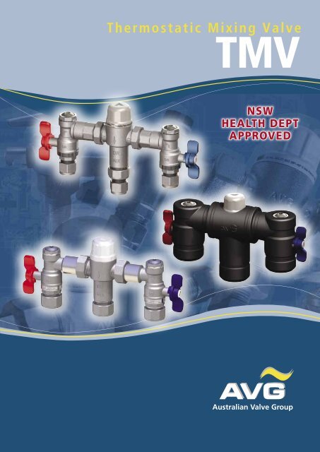
Thermostatic Mixing Valve<br />
<strong>TMV</strong><br />
NSW<br />
HEALTH DEPT<br />
APPROVED
Thermostatic Mixing Valve<br />
<strong>TMV</strong><br />
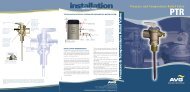
Thermostatic Mixing Valve is a high performance<br />
Thermostatic Mixing Valve suitable for a wide range of applications.<br />
The valve is designed to comply with Australian Standard<br />
AS4032.1 for Thermostatic Mixing Valves-Materials, Design<br />
and Performance Requirements and the NSW Health<br />
Department requirements.<br />
Features<br />
• Meets the requirements of AS4032.1Thermostatic Mixing Valves<br />
• Provides high stability of mixed water temperature even<br />
under changing inlet conditions<br />
• Ensures rapid shut down of mixed outlet flow in the event of hot,<br />
or cold water supply isolation<br />
• Easily serviced on site<br />
• Suitable for installation into AS3500 compliant systems with hot water<br />
temperature as low as 60°C<br />
• The adjustment mechanism can be locked to prevent tampering<br />
Recommended Pessures<br />
& Temperatures<br />
MIXED OUTLET TEMPERATURE<br />
Temperature Adjustment Range<br />
35°to 45°Celsius<br />
INLET TEMPERATURES<br />
Cold Supply 5°C - 25°C<br />
Hot Supply 60°C - 90°C<br />
Hot to Mix Temperature Differential<br />
for Stable operation Minimum 10°C<br />
Cold to Mix Temperature Differential<br />
for stable operation Minimum 5°C<br />
FLOW RATES<br />
To ensure stable outlet conditions<br />
Minimum 4 /minute<br />
<strong>TMV</strong> 20/15<br />
To ensure safety, the <strong>TMV</strong> must be installed<br />
and maintained strictly according to AVG’s<br />
installation instructions, Australian Standards<br />
and local regulatory requirements. AS3500<br />
now calls on all valves & pipe work to be<br />
insulated. AVG provide the insulation & cable<br />
ties with the mixing valves.<br />
WaterMark<br />
AS AS 4032.1 1357.2 Lic 20137 2639<br />
SAI Global<br />
TM<br />
DYNAMIC INLET PRESSURES<br />
Hot and Cold Inlet Pressures<br />
STATIC INLET PRESSURE<br />
Hot and Cold Inlet Pressures<br />
INLET PRESSURE RATIO<br />
Maximum inlet pressure ratio<br />
For stable operation<br />
(Hot: Cold or Cold:Hot)<br />
Minimum 20 kPa<br />
Maximum 500 kPa<br />
Maximum 1000kPa<br />
10:1 (either supply)<br />
<strong>TMV</strong> 20<br />
NOTE: For optimum operation it is recommended that the hot and cold water supply<br />
pressures be balanced to within +/- 10%.<br />
NOTE: Notwithstanding the above, compliance with AS3500 must be maintained.<br />
11
Suitable For Storage Hot Water Systems<br />
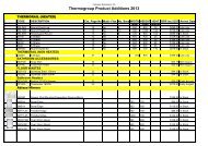
Valve Dimensions (Fig. 1)<br />
Valve Dimensions (Fig. 1)<br />
45.9<br />
<strong>TMV</strong> DIMENSION<br />
FLOW SIZING GRAPH<br />
The AVG Thermostatic Mixing Valve is suitable for many applications. The<br />
Headloss Characteristic for Mixed Outlet Flow rate verses Balanced Inlet<br />
Pressure is shown below in Graph 1. It is important that the valve<br />
is sized correctly.<br />
Note: To ensure optimum performance the minimum outlet flow of the mixing<br />
valve during operation should be at least 4 litres/minute.<br />
It is important that the valve and pipe work is sized such that they comply with<br />
those listed in AS3500.1.2. and -Appendix B to ensure the water velocity in the<br />
pipework is within the allowed limit.<br />
5. FLOW SIZING GRAPH<br />
If the valve is to be installed and operated under unequal inlet pressuresthe lower<br />
The AVG inlet pressure Thermostatic determines Mixing the Valve outlet is flow suitable rate. However, for many for applications. optimum performance The<br />
Headloss and stability Characteristic it recommended for Mixed that Outlet the valve Flowrate beinstalled verses with Balanced balanced Inlet dynamic<br />
Pressure inlet is pressures shown (+/- below 10%). in Graph 1. It is important that the valve is sized<br />
correctly.<br />
Graph 1<br />
60<br />
60<br />
56.8 54.5<br />
DR<br />
DR<br />
153.5<br />
153<br />
237.5<br />
222<br />
<strong>TMV</strong> STAINLESS STEEL bOx<br />
54<br />
5<br />
Note: To ensure optimum performance the minimum outlet flow of the<br />
mixing valve during operation should be at least 4 litres/minute.<br />
It is important that the valve and pipe work is sized such that they comply<br />
with those listed in AS3500.1.2. and -Appendix B to ensure the water<br />
velocity in the pipework is within the allowed limit.<br />
If the valve is to be installed and operated under unequal inlet pressures<br />
the lower inlet pressure determines the outlet flow rate. However, for<br />
optimum performance and stability it is recommended that the valve be<br />
installed with balanced dynamic inlet pressures (+/- 10%).<br />
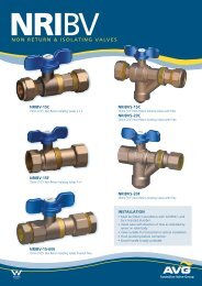
COLD SUPPLY<br />
A<br />
B<br />
C<br />
A B C D E F G F E D C B H<br />
PIPEWORK<br />
PRESSURE LIMITING VALVE (IF REQUIRED)<br />
ISOLATING VALVE<br />
J<br />
MIXED OUTLET<br />
F<br />
G<br />
H<br />
NON RETURN VALVE<br />
J<br />
THERMOSTAIC MIXING VALVE<br />
TEMPERATURE LIMITING VALE (IF REQUIRED)<br />
7<br />
HOT SUPPLY<br />
Schematic Installation Diagram (Fig. 2)<br />
D<br />
LINE STRAINER<br />
J<br />
RIGHT ANGLE BALL VALVE ASSEMBLY<br />
E<br />
COLD WATER TEST POINT
installation<br />
INSTRUCTIONS<br />
INSTALLATION<br />
The AVG Thermostatic Mixing Valve should be installed as per the<br />
appropriate Standard, Code of Practice and legislation applicable to<br />
each state and any local requirements and details outlined in this<br />
section.<br />
The AVG Thermostat Mixing Valve must be installed by a licensed<br />
plumber, or where applicable, a licensed plumber who has undertaken<br />
T.A.F.E. training in Thermostatic Mixing Valves.<br />
NOTE: To effectively control microbial hazards during system design,<br />
installation, commissioning and maintenance, it is important to adhere<br />
to the requirements outlined in AS/NZS3666 and local legislation.<br />
Inlets and outlet connections of the valve are clearly marked. The<br />
letters H and C cast into the valve body indicates the Hot and Cold inlet<br />
respectively. An arrow cast into the body of the valve identifies the valve<br />
outlet direction.<br />
If the valve is not installed correctly then the warranty will be void.<br />
Please note that the user may be in danger if the valve malfunctions.<br />
Check to ensure that the system operating conditions fall within the<br />
recommended operating range of the AVG Thermostatic Mixing Valve<br />
as detailed in Section 4. If the hot water supply temperature is greater<br />
than 90°C the valve may be damaged. A suitable temperature limiting<br />
valve must be fitted to the hot water supply, prior to the inlet fittings,<br />
if the temperature of the hot water will rise above 90°C. It is also<br />
important that both of the inlet dynamic supply pressures are 500kPa<br />
or less. If either supply pressure exceeds 500kPa then a suitable<br />
pressure reducing valve must be fitted prior to the inlet control valve to<br />
reduce the pressure to an acceptable limit. In order to achieve optimum<br />
performance from the valve it is recommended that the inlet pressures<br />
are balanced to within 10% of each other.<br />
The water quality conditions should comply and not exceed the limits as<br />
listed in AS3500.4, Appendix B.<br />
It may be necessary to install a water softener or water treatment<br />
device.<br />
NOTE: In some installations, flick mixers and solenoid valves are used.<br />
The water pressure may be seen to spike outside that recommended<br />
for the valve, during rapid shut off conditions. Even if the spike only<br />
lasts for a split second it is still considered to be outside the operating<br />
conditions and may cause the valve to operate incorrectly.<br />
If this does occur, then measures must be taken to control the spike,<br />
such as inline pressure reducing valves directly before the valve inlets.<br />
Thoroughly flush the pipe work with clean water to remove any<br />
swarf or debris before the valve is installed. Care should be taken to<br />
prevent water damage occurring during this procedure.<br />
It is required by AS3500.4 section 3.3 that “Each thermostatic mixing<br />
valve shall have an isolating stop tap/valve, line strainer and non-return<br />
valve fitted to the hot and cold water supply lines”. The inlet fittings<br />
supplied with each <strong>TMV</strong> will ensure this requirement is met. If the AVG<br />
Thermostatic Mixing Valve is installed without the supplied inlet control<br />
valves then it will be necessary to install a separate isolating valve for<br />
ease of servicing, a non-return valve to prevent cross –connection and a<br />
strainer to both inlets to the valve.<br />
Ensure that the test plugs in the top of the inlet fittings are water tight.<br />
Install the valve so that it can be accessed easily for maintenance or<br />
servicing. The valve can be installed in a wall cavity, under a basin or on<br />
a wall, however it is essential that the mixing valve and inlet fittings are<br />
easily accessible for servicing.<br />
During installation or servicing heat must not be applied near the mixing<br />
valve or inlet fittings, as this will damage the valve and inlet fitting<br />
internals.<br />
Note: The AVG Thermostatic Mixing Valve is intended mainly for use in<br />
applications with set temperatures of 45°C. or below. When installed at<br />
higher set temperature, the performance may be less than specified in<br />
AS4032.1.<br />
If the set temperature required is higher, then an AVG Tempering Valve<br />
approved to AS4032.2 would provide a greater margin for safety in reducing<br />
scalding accidents..<br />
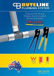
TEMPERATURE ADJUSTMENT<br />
1. Using a small flat bladed screw driver lever the protective cap off the<br />
valve.<br />
2. Fit the cap over the adjusting spindle.<br />
To increase the mixed outlet temperature, rotate the spindle anticlockwise.<br />
To decrease the mixed outlet temperature, rotate the<br />
spindle Valve clockwise. Adjustment Adjustment (Fig. 3)<br />
3. Allow the mixed outlet temperature to stabilize ADJUSTMENT for TOOL 60 seconds and<br />
MOULDED INTO CAP<br />
once again take a temperature reading. Repeat the procedure until the<br />
desired temperature has been reached.<br />
REMOVE<br />
4. Tighten the lock nut and push the protective cap firmly on to the top of<br />
TO ADJUST<br />
CAP<br />
the valve until it ‘snaps’ back into place.<br />
5. Check that the outlet temperature is stable over the full range offlow<br />
rates and that the flow rate is adequate for the application.<br />
6. Close the outlet.<br />
7. The mixing valve is now set and locked.<br />
Valve Adjustment Adjustment (Fig. 3)<br />
14<br />
FIT & ROTATE CAP ANTI-CLOCKWISE<br />
TO INCREASE TEMPERATURESETTING<br />
ADJUSTMENT TOOL<br />
MOULDED INTO CAP<br />
REMOVE CAP<br />
TO ADJUST<br />
FIT & ROTATE CAP ANTI-CLOCKWISE<br />
TO INCREASE TEMPERATURESETTING<br />
14<br />
Australian Valve Group (Head Office)<br />
Unit 2, 9-11 Noble St, Kewdale, Perth, Western Australia 6105<br />
Fax: +61 8 9353 2689 Tel: 1800 AVG AUS (284 287)<br />
FOR MORE INFORMATION VISIT OUR WEBSITE AT WWW.AVG.NET.AU