➊ millimeters precisely before
Siemens VDO - Vehicle Controls
Siemens VDO - Vehicle Controls

Create successful ePaper yourself
Turn your PDF publications into a flip-book with our unique Google optimized e-Paper software.
&<br />
!<br />
!-"%"]]<br />
"%#&$]]<br />
-"%"]]<br />
! !&<br />
-"%&]]<br />
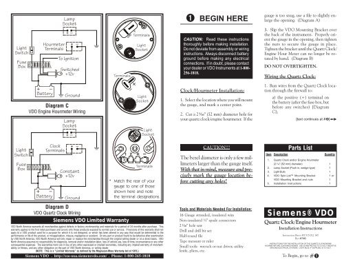
➋ CONTINUE HERE<br />
this positive power source MUST<br />
BE UNSWITCHED, but should<br />
be protected with a fuse);<br />
b) the light switch (also after the<br />
fuse in the fuse box); and<br />
c) a good ground location (i.e.,<br />
anywhere you can conveniently<br />
bolt the wire to the chassis of the<br />
vehicle).<br />
2. Connect the appropriate positive (+)<br />
and ground (negative [–]) wires to the<br />
clock and clock lamp socket as shown in<br />
Diagram D.<br />
Wiring the Engine Hour Meter<br />
1. Run wires from the Engine Hour Meter<br />
location through the firewall to:<br />
a) the positive (+) terminal on<br />
the ignition switch (after the fuse<br />
box);<br />
b) the light switch (also after the<br />
fuse in the fuse box); and<br />
c) a good ground location (i.e.,<br />
anywhere you can conveniently<br />
bolt the wire to the chassis of the<br />
vehicle).<br />
2. Connect the appropriate positive (+)<br />
and ground (negative [–]) wires to the<br />
Engine Hourmeter and Hourmeter lamp<br />
socket as shown in Diagram C.<br />
At this point, the installation and wiring<br />
of your new VDO Quartz Clock/Engine<br />
Hour Meter is complete. Turn on the ignition<br />
and the lights in the car and check to<br />
see that the clock/hourmeter and light are<br />
working properly. If they are not, recheck<br />
your wiring.<br />
]Qh (" ]]<br />
-"%&]]<br />
Mounting hole dimension = 2¹⁄₁₆" (52 mm)<br />
Diagram A<br />
Gauge dimensions<br />
-"%"]]<br />
! !&<br />
#((]]<br />
DO NOT OVERTIGHTEN!<br />
Mounting Nut direction<br />
depends on panel width<br />
A: 0 – .4" (0 – 10 mm)<br />
B: .4" – .8" (10 – 20 mm)<br />
é<br />
TOP:<br />
VDO’s Spin-Lok ä<br />
Mounting Clamp<br />
LEFT:<br />
ç VDO Mounting Bracket<br />
Diagram B<br />
Mounting using VDO Mounting Bracket or VDO Spin-Lok ä Clamp
9W^YdY_^CgYdSXUT!"f<br />
➋ CONTINUE HERE<br />
c) the positive (+) terminal on<br />
the ignition switch.<br />
2. Connect the wires from the alternator,<br />
starter and ignition to the terminals on the<br />
back of the ammeter as shown in Diagram<br />
C.<br />
3. Connect the wire from the light switch<br />
(after the fuse box) and from a ground location<br />
to the ammeter light switch terminals,<br />
also as shown in Diagram C.<br />
At this point, the installation and wiring<br />
of your ammeter is complete. Turn on the<br />
ignition and start the engine to be sure the<br />
ammeter is working properly. If it isn’t, recheck<br />
your wiring.<br />
<br />
<br />
PP<br />
<br />
PP<br />
é PP<br />
PD[ PP<br />
PP<br />
Diagram A<br />
Gauge dimensions<br />
Diagram B<br />
Proper mounting of the VDO Ammeter
Light<br />
Switch<br />
Light<br />
Switch<br />
Fuse<br />
Box<br />
Fuse<br />
Box<br />
Light<br />
Switch<br />
Fuse<br />
Box<br />
Battery<br />
Battery<br />
Hour Meter<br />
Terminal<br />
Hour Meter<br />
Terminals<br />
Optional<br />
Illumination<br />
( )<br />
Clock<br />
Terminals<br />
Optional<br />
Illumination<br />
( )<br />
+<br />
+<br />
Ground<br />
Diagram B Clock Wiring Diagram<br />
Battery<br />
+<br />
Constant<br />
+12v<br />
Ground<br />
+–<br />
Optional<br />
( Illumination )<br />
+ –<br />
Optional<br />
( Pressure Switch)<br />
+ –<br />
Option 1 - Diagram C Engine Hourmeter Wiring Diagram<br />
Option 2 - Diagram C<br />
Engine Hourmeter Wiring Diagram<br />
DO NOT OVERTIGHTEN!<br />
SiemensVDO Limited Warranty<br />
Siemens VDO warrants all merchandise against defects in factory workmanship and materials for a period of 24 months after purchase. This<br />
warranty applies to the first retail purchaser and covers only those products exposed to normal use or service. Provisions of this warranty shall not<br />
apply to a Siemens VDO product used for a purpose for which it is not designed, or which has been altered in any way that would be detrimental<br />
to the performance or life of the product, or misapplication, misuse, negligence or accident. On any part or product found to be defective after<br />
examination by SiemensVDO , Siemens VDO will only repair or replace the merchandise through the original selling dealer or on a direct basis.<br />
Siemens VDO assumes no responsibility for diagnosis, removal and/or installation labor, loss of vehicle use, loss of time, inconvenience or any other<br />
consequential expenses. The warranties herin are in lieu of any other expressed or implied warranties, including any implied warranty of merchantability<br />
or fitness, and any other obligation on the part of Siemens VDO, or selling dealer.<br />
Siemens VDO . http://sso-usa.siemensvdo.com/ . Phone: 1-800-265-1818<br />
Siemens VDO ®<br />
Clock/Engine Hourmeter<br />
Installation Instructions<br />
Instruction Sheet # 0 515 012 157<br />
Rev. 10/03<br />
-<br />
!"f<br />
Illumination<br />
C A UT ION: R ea d these ins tructions<br />
thoroughly <strong>before</strong> making installation.<br />
Do not deviate from assembly or wiring<br />
instructions.<br />
Mounting Nut direction<br />
depends on panel w idt h<br />
A: 0 – .4" (0 – 10 mm)<br />
CAUTION: B: Read .4" – .8 " (10 these – 20 mm) instructions<br />
t<br />
ç<br />
TOP:<br />
VDO’s Spin-Lok ä<br />
Mounting Clamp<br />
LEFT:<br />
VDO Mounting Bracket<br />
Diagram A - Mounting using optional<br />
VDO Mounting Bracket or VDO Spin-Lok Clamp<br />
<br />
é<br />
Instrument Mounting Diagram A:<br />
1. Prior to any work on vehicle's wiring<br />
system, removing the (-) negative battery<br />
cable from the battery to disable battery<br />
power.<br />
2. Find a suitable location to mount the<br />
instrument where there is ample depth to<br />
secure and wire instrument.<br />
3. Cut a 2 1/16" (52 mm) diameter hole<br />
in the location selected. Instrument should<br />
fit into hole easily without forcing. Forcing<br />
it may cause damage to housing of<br />
instrument.<br />
4. Secure 'Spin Lok' clamp (Diagram A)<br />
on to instrument. (Note) the 'Spin Lok'<br />
clamp is designed to work in thin panels<br />
as well as panels up to .8" (20 mm)<br />
in thickness. Consequently, if 'Spin Lok'<br />
clamp is installed and will not securely<br />
fasten instrument, remove, reverse and<br />
re-install.<br />
5. If you are using optional metal mounting<br />
bracket, install with mounting nuts,<br />
For thicker panels it may be necessary to<br />
trim legs accordingly.<br />
Clock Wiring Digram C:<br />
1. Wire + terminal to a fused 12 v battery<br />
source that is not switched off when<br />
vehicle ignition is off.<br />
2. Wire - terminal to a good ground<br />
location.<br />
3. If the instrument you have purcased<br />
has an illumination terminal K, wire to<br />
the light switch of the vehicle so that the<br />
instrument light turns off and on when the<br />
switch is operated.<br />
4. Reconnect battery ground cable and<br />
test for operation.<br />
CAUTION!!!<br />
Secured with Spin- Lok or metal<br />
braket tight enough to prevent rotation<br />
of instrument.<br />
DO NOT OVER TIGHTEN<br />
INSTRUMENT OR DAMAGE<br />
WILL OCCURE TO HOUSING<br />
AND BEZEL.<br />
Hour Meter Wiring<br />
Option 1- Digram C:<br />
1. Wire + terminal to a fused 12/24v<br />
battery source that is switched off when<br />
vehicle is not in operation.<br />
2. Wire - terminal to a good ground<br />
location.<br />
3. If the instrument you have purcased<br />
has an illumination terminal K, wire to<br />
the light switch of the vehicle so that the<br />
instrument light turns off and on when the<br />
switch is operated.<br />
4. Reconnect battery ground cable and<br />
test for operation.<br />
(Note) Since the hourmeter registers<br />
in 10 th of hours, it will take 6 minutes<br />
<strong>before</strong> hourmeter will show movement.<br />
Hour Meter Wiring<br />
Option 2 - Digram C:<br />
1. Wire + terminal to a fused 12/24v<br />
battery source that remains on even<br />
vehicle igniton is off.<br />
2. Wire - terminal directly to a normally<br />
open engine oil pressure switch.<br />
When engine is started and oil pressure<br />
CAUTIO<br />
rises the pressue switch will close and CAUTION<br />
the hour meter will begin to operate.<br />
3. If the instrument you have purchased<br />
has an illumination terminal K, wire to<br />
the light switch of the vehicle so that the<br />
instrument light turns off and on when the<br />
switch is operated.<br />
4. Reconnect battery ground cable and<br />
start vehicle. When oil pressure present<br />
observe operation of instrument.<br />
(Note) Since the hourmeter registers<br />
in 10 th of hours, it will take 6 minutes<br />
<strong>before</strong> hourmeter will show movement.<br />
Clock Setting<br />
1. Button on bottom left of clock face<br />
will set counter clock wise<br />
2. Button on bottom right of clock face<br />
will set clock wise<br />
3. By hold left or right button down<br />
will make the clock set faster