0 511 012 428 -- Dual Shift Point Eliminator Tach ... - Vehicle Controls
0 511 012 428 -- Dual Shift Point Eliminator Tach ... - Vehicle Controls
0 511 012 428 -- Dual Shift Point Eliminator Tach ... - Vehicle Controls
- No tags were found...

You also want an ePaper? Increase the reach of your titles
YUMPU automatically turns print PDFs into web optimized ePapers that Google loves.
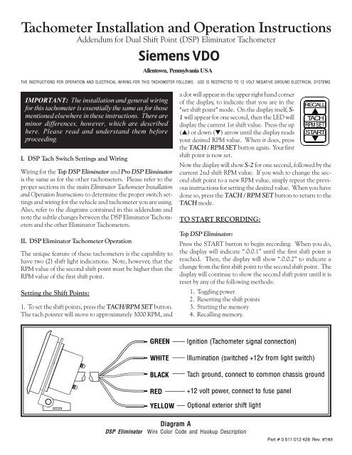
<strong>Tach</strong>ometer Installation and Operation Instructions<br />
Addendum for <strong>Dual</strong> <strong>Shift</strong> <strong>Point</strong> (DSP) <strong>Eliminator</strong> <strong>Tach</strong>ometer<br />
Siemens VDO<br />
Allentown, Pennsylvania USA<br />
THE INSTRUCTIONS FOR OPERATION AND ELECTRICAL WIRING FOR THIS TACHOMETER FOLLOWS. USE IS RESTRICTED TO 12 VOLT NEGATIVE GROUND ELECTRICAL SYSTEMS.<br />
IMPORTANT: The installation and general wiring<br />
for this tachometer is essentially the same as for those<br />
mentioned elsewhere in these instructions. There are<br />
minor differences, however, which are described<br />
here. Please read and understand them before<br />
proceeding.<br />
I. DSP <strong>Tach</strong> Switch Settings and Wiring<br />
Wiring for the Top DSP <strong>Eliminator</strong> and Pro DSP <strong>Eliminator</strong><br />
is the same as for the other tachometers. Please refer to the<br />
proper sections in the main <strong>Eliminator</strong> <strong>Tach</strong>ometer Installation<br />
and Operation Instructions to determine the proper switch settings<br />
and wiring for the vehicle and tachometer you are using.<br />
Also, refer to the diagrams contained in this addendum and<br />
note the subtle changes between the DSP <strong>Eliminator</strong> <strong>Tach</strong>ometers<br />
and the other <strong>Eliminator</strong> <strong>Tach</strong>ometers.<br />
II. DSP <strong>Eliminator</strong> <strong>Tach</strong>ometer Operation<br />
The unique feature of these tachometers is the capability to<br />
have two (2) shift light indications. Note, however, that the<br />
RPM value of the second shift point must be higher than the<br />
RPM value of the first shift point.<br />
Setting the <strong>Shift</strong> <strong>Point</strong>s:<br />
1. To set the shift points, press the TACH/RPM SET button.<br />
The tach pointer will move to approximately 3000 RPM, and<br />
a dot will appear in the upper right hand corner<br />
of the display, to indicate that you are in the RECALL<br />
“set shift point” mode. On the display itself, S- ▲<br />
1 will appear for one second, then the LED will TACH<br />
display the current 1st shift value. Press the up<br />
(▲) or down (▼) arrow until the display reads START<br />
your desired RPM value. When it does, press ▼<br />
the TACH / RPM SET button again. Your first<br />
shift point is now set.<br />
Now the display will show S-2 for one second, followed by the<br />
current 2nd shift RPM value. If you wish to change the second<br />
shift point to a new RPM value, simply repeat the previous<br />
instructions for setting the desired value. When you have<br />
done so, press the TACH / RPM SET button to return to the<br />
TACH mode.<br />
TO START RECORDING:<br />
Top DSP <strong>Eliminator</strong>:<br />
Press the START button to begin recording. When you do,<br />
the display will indicate “.0.0.1” until the first shift point is<br />
reached. Then, the display will show “.0.0.2” to indicate a<br />
change from the first shift point to the second shift point. The<br />
display will continue to show the second shift point until it is<br />
reset by any of the following methods:<br />
1. Toggling power<br />
2. Resetting the shift points<br />
3. Starting the memory<br />
4. Recalling memory.<br />
*5((1<br />
:+,7(<br />
%/$&.<br />
5('<br />
Pro DSP <strong>Eliminator</strong>:<br />
Setting shift points for the Pro DSP <strong>Eliminator</strong> is the same as<br />
for setting shift points for the Top DSP <strong>Eliminator</strong>, except for<br />
the following:<br />
When you press the clear button, the display will flash “0.00”<br />
twice, followed by the 1st shift point value. After the 1st shift<br />
point value is reached, the 2nd shift point value is displayed<br />
until reset as described previously.<br />
RECALL:<br />
To recall your recording, follow the procedures outlined for all<br />
<strong>Eliminator</strong> <strong>Tach</strong>ometers in the main Installation and Operating<br />
Instructions.<br />
Diagram B<br />
DSP <strong>Eliminator</strong> Dimensions and Switch Settings
ON
Siemens VDO http://sso-usa.siemensvdo.com/ Phone: 1-800-265-1818
PP<br />
Performance <strong>Shift</strong> Light <strong>Tach</strong>ometer<br />
Performance <strong>Tach</strong>ometer<br />
Installation and Operation Instructions<br />
Siemens VDO<br />
Allentown, Pennsylvania USA<br />
THE INSTRUCTIONS FOR INSTALLATION AND ELECTRICAL WIRING FOR THESE TACHOMETERS FOLLOW. USE IS RESTRICTED TO 12 VOLT NEGATIVE GROUND ELECTRICAL SYSTEMS.<br />
Parts List<br />
Item Description Quantity<br />
1. <strong>Tach</strong>ometer 1<br />
2. Decals, 2” x 4” (not contingency decals) 2<br />
3. Green Lamp Cover 2<br />
4. Red Lamp Cover 2<br />
CAUTION: Read these instructions thoroughly before making installation.<br />
Always wear safety glasses, and always disconnect the battery<br />
ground before making any electrical connections. If in doubt,<br />
please contact your dealer or VDO Instruments at 1-800-265-1818.<br />
<strong>Tach</strong>ometer Installation<br />
1. Cylinder Selection<br />
Your tachometer is factory programmed for an eight cylinder<br />
engine. For other applications the selector switches must<br />
be set according to Diagram A.<br />
· Remove the 3 Philips head screws from the rear cover.<br />
· Remove the rear cover.<br />
· Find your application in Diagram A and set the<br />
switches accordingly.<br />
· Replace the rear cover and three screws.<br />
DO NOT OVERTIGHTEN!<br />
<br />
PP<br />
<br />
3 2 1<br />
OFF<br />
ON<br />
6HOHFWRU<br />
6ZLWFKHV<br />
3 2 1<br />
OFF<br />
ON<br />
/DPS<br />
$VVHPEOLHV<br />
6(/(&7256:,7&+6(77,1*6<br />
&
2. Colored Illumination<br />
You may use the colored lamp covers to customize your<br />
tachometer’s illumination.<br />
· Remove the 3 Phillips head screws from the rear cover.<br />
· Remove the rear cover.<br />
· Using long nose pliers, gently grip one of the lamp<br />
assemblies and give it about a quarter-turn counterclockwise.<br />
· Lift the lamp assembly straight out.<br />
· Slide the colored lamp cover of your choice over the<br />
bulb section of the lamp assembly.<br />
· Reinsert the lamp assembly, and lock it into position<br />
with about a quarter-turn clockwise.<br />
· Repeat this procedure for the second lamp assembly.<br />
· Replace the rear cover and the three screws.<br />
DO NOT OVERTIGHTEN!<br />
3. Mounting the <strong>Tach</strong>ometer<br />
Determine the mounting position for your <strong>Tach</strong>ometer that<br />
is best for you. The mounting bracket may be bent to adjust<br />
the viewing angle of your <strong>Tach</strong>ometer’s face.<br />
· Recommended installation is on the steering column<br />
using a band clamp (available at a local auto parts<br />
store).<br />
· Dash mounting uses the two holes provided in the base<br />
of the mounting bracket to secure the tachometer to<br />
the dash.<br />
4. Wiring the <strong>Tach</strong>ometer<br />
· Turn off the ignition and disconnect the negative<br />
terminal from the battery post if you haven’t already<br />
done so.<br />
· Wire the tachometer to the vehicle as shown in<br />
Diagram A.<br />
** Refer to your vehicle’s owner/service manual or the<br />
aftermarket ignition manufacturer’s instructions for<br />
the recommended place to tap the signal. Typical<br />
examples are shown in the table at upper right.<br />
· Reconnect the battery and start your vehicle to test.<br />
IGNITION TYPE CONNECTIONS<br />
Standard points/ breakerless negative terminal on<br />
coil<br />
CD points points connection to<br />
CD box<br />
breakerless<br />
positive terminal on<br />
coil<br />
Electronic MSD, ACCEL, <strong>Tach</strong> output terminal<br />
MALLORY, DDIS on ignition box, or<br />
(distributorless), points connection to<br />
etc.<br />
ignition box, or<br />
negative coil<br />
5. <strong>Shift</strong> Light Operation<br />
(Performance <strong>Shift</strong> Light <strong>Tach</strong>ometers Only)<br />
The RED <strong>Shift</strong> Light on your <strong>Tach</strong>ometer’s face (refer to<br />
Diagram A) will light up whenever your engine is running at<br />
or above your pre-set <strong>Shift</strong> <strong>Point</strong> RPM.<br />
1. Setting the <strong>Shift</strong> <strong>Point</strong>:<br />
· Turn ON the ignition. The engine MAY be running.<br />
· Push in the <strong>Shift</strong> Light Control Knob (Diagram A).<br />
· The RED <strong>Shift</strong> Light will turn on and the tachometer<br />
pointer will show the current <strong>Shift</strong> <strong>Point</strong> RPM.<br />
· While holding in the Control Knob, slowly turn it until<br />
the tachometer pointer indicates your desired <strong>Shift</strong><br />
<strong>Point</strong> RPM.<br />
· Release the Control Knob. The <strong>Shift</strong> Light will turn<br />
OFF and your <strong>Shift</strong> <strong>Point</strong> RPM is set.<br />
2. Checking the <strong>Shift</strong> <strong>Point</strong>:<br />
You can quickly check your <strong>Shift</strong> <strong>Point</strong> RPM at any time,<br />
even while the engine is RUNNING:<br />
· Turn ON the ignition. The engine MAY be running.<br />
· Push in the <strong>Shift</strong> Light Control Knob.<br />
· The RED <strong>Shift</strong> Light will turn on and the tachometer<br />
pointer will show the current <strong>Shift</strong> <strong>Point</strong> RPM.<br />
VDO North America, LLC. warrants all merchandise against defects in factory workmanship<br />
and materials for a period of 24 months after purchase. This warranty<br />
applies to the first retail purchaser and covers only those products exposed to<br />
normal use or service. Provisions of this warranty shall not apply to a VDO product<br />
used for a purpose for which it is not designed, or which has been altered in any<br />
way that would be detrimental to the performance or life of the product, or misapplication,<br />
misuse, negligence or accident. On any part or product found to be<br />
defective after examination by VDO North America, VDO North America will only<br />
Siemens VDO Limited Warranty<br />
repair or replace the merchandise through the original selling dealer or on a direct<br />
basis. VDO North America assumes no responsibility for diagnosis, removal and/<br />
or installation labor, loss of vehicle use, loss of time, inconvenience or any other<br />
consequential expenses. The warranties herin are in lieu of any other expressed or<br />
implied warranties, including any implied warranty of merchantability or fitness,<br />
and any other obligation on the part of VDO North America, or selling dealer.<br />
(NOTE: This is a “Limited Warranty” as defined by the Magnuson-Moss Warranty<br />
Act of 1975.)<br />
Siemens VDO Instruments . http://sso-usa.siemensvdo.com/ . Phone: 1-800-265-1818