Tachometer
0 515 010 561 -- PRT Tachometer.p65 - Vehicle Controls
0 515 010 561 -- PRT Tachometer.p65 - Vehicle Controls
- No tags were found...

Create successful ePaper yourself
Turn your PDF publications into a flip-book with our unique Google optimized e-Paper software.
THE INSTRUCTIONS FOR INSTALLATION AND ELECTRICAL WIRING FOR THESE TACHOMETERS FOLLOW. USE IS RESTRICTED TO 12 VOLT NEGATIVE GROUND ELECTRICAL SYSTEMS.<br />
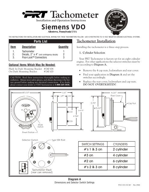
Parts List<br />
Item Description Quantity<br />
1. <strong>Tachometer</strong> 1<br />
2. Decals, 2” x 4” (not contingency decals) 2<br />
3. Posi-Lock Connectors 3<br />
Optional Items Which May Be Needed:<br />
Flush In-Dash Mounting Bracket #240 104<br />
On-Dash Mounting Bracket #240 103<br />
CAUTION: Read these instructions thoroughly before making installation.<br />
Always wear safety glasses, and always disconnect the battery<br />
ground before making any electrical connections. If in doubt,<br />
please contact your dealer or VDO Instruments at 1-800-265-1818.<br />
<strong>Tachometer</strong><br />
Installation and Operation Instructions<br />
Siemens<br />
Allentown, Pennsylvania USA<br />
VDO<br />
<strong>Tachometer</strong> Installation<br />
Installing the tachometer is a three-step process.<br />
1. Cylinder Selection<br />
Your PRT <strong>Tachometer</strong> is factory set for an eight cylinder<br />
engine. For other applications the selector switches must be<br />
set according to Diagram A.<br />
· Remove the 4 cap nuts, lockwashers and rear cover.<br />
· Find your application in Diagram A and set the<br />
switches accordingly.<br />
· Replace the rear cover, lockwashers and cap nuts.<br />
DO NOT OVERTIGHTEN!<br />
% <br />
#"%<br />
'% !&# ((<br />
$ <br />
BUQb3_fUb<br />
%'%<br />
3Q`>ed<br />
$'%<br />
% <br />
#!(<br />
=_TU<br />
CgYdSX<br />
BUcUd2edd_^<br />
CU\USd_bCgYdSX<br />
Di`U!)$2e\R<br />
·V RQ<br />
F\OLQGHU<br />
1<br />
<br />
2<br />
RQ<br />
F\OLQGHU<br />
RQ<br />
F\OLQGHU<br />
1<br />
<br />
2<br />
DQSX_]UdUb2QS[<br />
bUQbSQ^bU]_fUT<br />
·V RQ<br />
F\OLQGHU<br />
Diagram A<br />
Dimensions and Selector Switch Settings<br />
P/N 0 515 010 561 Rev. 07/03
&ROXPQ0RXQW<br />
2Q'DVK<br />
9^4QcX<br />
8QGHU'DVK<br />
5ROO%DU<br />
0RXQW<br />
Diagram B<br />
Possible mounting locations for the Extreme <strong>Tachometer</strong><br />
2. Mounting the <strong>Tachometer</strong><br />
Your PRT tachometer can be mounted almost anywhere.<br />
Several suggestions are illustrated in Diagram B. Some<br />
installation techniques may require optional accessories,<br />
cutting, or drilling new holes.<br />
MOUNTING NOTES:<br />
· The most common mounting location is on the steering<br />
column or roll cage using a band clamp and the<br />
included short mounting bracket.<br />
· For mounting in the dash, optional flush mounting<br />
bracket [P/N 240 104] is recommended. The rear<br />
cover may also be used as a mounting clamp for in<br />
dash mounting.<br />
· For mounting on top of the dash, optional longer<br />
mounting bracket [P/N 240 103] is recommended.<br />
MOUNTING CAUTIONS:<br />
· Make sure your PRT <strong>Tachometer</strong> does not rest against<br />
any glass, windshield A pillars, or any roll cage tubes.<br />
· VDO does not recommend mounting your PRT<br />
<strong>Tachometer</strong> close to other electrical components or<br />
their associated wiring. For example, the ignition<br />
system box, the ignition coil, electric fuel pump, etc.<br />
IGNITION<br />
Standard<br />
CD<br />
Electronic<br />
TYPE<br />
points/ breakerless<br />
points<br />
breakerless<br />
MSD, ACCEL,<br />
MALLORY, DDIS<br />
(distributorless),etc.<br />
CONNECTIONS<br />
negative terminal on coil<br />
points connection to CD box<br />
positive terminal on coil<br />
Tach output terminal on ignition<br />
box, or points connection to<br />
ignition box, or negative coil<br />
· Be sure to connect the tachometer using the supplied<br />
Posi-Lock Connectors. Use them as shown in the<br />
following illustration:<br />
¯<br />
°<br />
CdbY`gYbUU^TcQR_ed<br />
9^cUbdUQSXgYbUY^d_Q]Q\UU^T<br />
Uh`_cY^W_^\iRQbUgYbU<br />
3. Wiring the <strong>Tachometer</strong><br />
· Turn off the ignition and disconnect the negative<br />
terminal from the battery post if you haven’t already<br />
done so.<br />
· Wire the tachometer to the vehicle as shown in<br />
Diagram C *.<br />
±<br />
8Q^TdYWXdU^]Q\UU^Tc<br />
Y^d_U^Tc_VRQbbU\<br />
* Refer to your vehicle’s owner/service manual or the<br />
aftermarket ignition manufacturer’s instructions for<br />
a recommended place to tap the signal. Typical<br />
examples are shown in the table to the right.<br />
· Reconnect the battery and start your vehicle to test<br />
the installation.
5('<br />
%/$&.<br />
*5((1<br />
YROWSRZHUDQGLOOXPLQDWLRQFRQQHFWWRIXVHSDQHO<br />
7DFKJURXQGFRQQHFWWRFRPPRQFKDVVLVJURXQG<br />
,JQLWLRQ7DFKRPHWHUVLJQDOFRQQHFWLRQ<br />
Diagram C<br />
General Wiring Information<br />
PRT <strong>Tachometer</strong> Operation<br />
For normal operation and display of current engine speed,<br />
rotate the Mode Switch to the TACH position.<br />
=_TU<br />
CgYdSX<br />
High RPM Recall Operation<br />
²DQSX³<br />
@_cYdY_^<br />
The PRT will store and display the highest engine speed<br />
achieved during a race. The high RPM recall is displayed by<br />
the tachometer pointer when in “RECALL” mode.<br />
1. Display high RPM memory.<br />
· Turn the igniton ON. The engine MAY be running.<br />
· Rotate the Mode Switch to the “RECALL” position.<br />
=_TU<br />
CgYdSX<br />
²BUSQ\\³<br />
@_cYdY_^<br />
· The pointer will move to indicate the high RPM stored<br />
by the tachometer.<br />
· Rotate the Mode Switch to the “TACH” position to<br />
return to normal tachometer operation.<br />
2. Resetting the memory.<br />
· Turn the ignition ON. The engine MAY be running.<br />
· Rotate the Mode Switch to the “RECALL” position.<br />
NOTE: The PRT memory cannot be RESET if<br />
the Mode Switch is not in the “RECALL”<br />
position.<br />
· The pointer will move to indicate the high RPM stored<br />
by the tachometer.<br />
· Press the RESET button.<br />
BUcUd<br />
2edd_^<br />
=_TU<br />
CgYdSX<br />
=ecd2U<br />
Y^dXU<br />
²BUSQ\\³<br />
@_cYdY_^<br />
· The pointer will drop to zero. (If the engine is running,<br />
the pointer will drop to the current engine speed.)<br />
· Rotate the Mode Switch to the “TACH” position to<br />
return to normal tachometer operation.<br />
VDO North America, LLC. warrants all merchandise against defects in factory workmanship<br />
and materials for a period of 24 months after purchase. This warranty<br />
applies to the first retail purchaser and covers only those products exposed to<br />
normal use or service. Provisions of this warranty shall not apply to a VDO product<br />
used for a purpose for which it is not designed, or which has been altered in any<br />
way that would be detrimental to the performance or life of the product, or misapplication,<br />
misuse, negligence or accident. On any part or product found to be<br />
defective after examination by VDO North America, VDO North America will only<br />
Siemens VDO Limited Warranty<br />
repair or replace the merchandise through the original selling dealer or on a direct<br />
basis. VDO North America assumes no responsibility for diagnosis, removal and/<br />
or installation labor, loss of vehicle use, loss of time, inconvenience or any other<br />
consequential expenses. The warranties herin are in lieu of any other expressed or<br />
implied warranties, including any implied warranty of merchantability or fitness,<br />
and any other obligation on the part of VDO North America, or selling dealer.<br />
(NOTE: This is a “Limited Warranty” as defined by the Magnuson-Moss Warranty<br />
Act of 1975.)<br />
Siemens VDO . http://sso-usa.siemensvdo.com/ . Phone: 1-800-265-1818
PP<br />
<br />
3DQHO<br />
*DXJH<br />
➊ BEGIN HERE<br />
CAUTION: Read these instructions thoroughly<br />
before making installation. Do not deviate from<br />
assembly or wiring instructions. Always<br />
disconnect battery ground before making any<br />
electrical connections. If in doubt, please<br />
contact your dealer or VDO Instruments at 1-800-<br />
265-1818.<br />
General Information:<br />
Your VDO mechanical temperature gauge<br />
features the latest illumination technology<br />
and a rugged design to insure years of durable<br />
and reliable operation. This instrument<br />
may require additional adapters to<br />
complete installation with various engines.<br />
You may purchase these adapters from your<br />
VDO dealer.<br />
Gauge Installation:<br />
1. Select the location where you will mount<br />
the gauge, and mark a center point for a<br />
hole (or use a VDO Mounting Accessory<br />
[1,2, & 3 hole chrome and black] or a VDO<br />
Mounting Cup [chrome or black]).<br />
2. Cut a 2⁵⁄₈" (65 mm) diameter hole for<br />
the temperature gauge. Place the instrument<br />
into the hole. If the gauge is too snug,<br />
use a file to slightly enlarge the opening<br />
until the gauge fits properly. (Diagram A)<br />
4. Slip the mounting bracket over the<br />
mounting bolts on the back of the gauge.<br />
Screw on the accompanying nuts. Tighten<br />
the nuts until the gauge can no longer be<br />
rotated by hand. DO NOT OVER-<br />
TIGHTEN!<br />
Diagram A<br />
Gauge Dimensions<br />
0RXQWLQJ<br />
%UDFNHW<br />
Parts List<br />
Item Description Quantity<br />
1. Temperature Gauge (2⁵⁄₈" [65 mm] diameter) 1<br />
2. ½" Adapter 1<br />
3. Lamp Socket 1<br />
4. Light Bulb 1<br />
5. VDO Mounting Bracket and nuts 1<br />
6. Installation Instructions 1<br />
CAUTION!!!<br />
The bezel diameter is only a few millimeters<br />
larger than the gauge itself.<br />
With that in mind, measure and precisely<br />
mark the gauge location before<br />
cutting any holes!<br />
Siemens VDO Limited Warranty<br />
VDO North America warrants all merchandise against defects in factory workmanship and materials for a period of 24 months after purchase. This<br />
warranty applies to the first retail purchaser and covers only those products exposed to normal use or service. Provisions of this warranty shall not<br />
apply to a VDO product used for a purpose for which it is not designed, or which has been altered in any way that would be detrimental to the<br />
performance or life of the product, or misapplication, misuse, negligence or accident. On any part or product found to be defective after examination<br />
by VDO North America, VDO North America will only repair or replace the merchandise through the original selling dealer or on a direct basis. VDO<br />
North America assumes no responsibility for diagnosis, removal and/or installation labor, loss of vehicle use, loss of time, inconvenience or any other<br />
consequential expenses. The warranties herein are in lieu of any other expressed or implied warranties, including any implied warranty of merchantability<br />
or fitness, and any other obligation on the part of VDO North America, or selling dealer.<br />
(NOTE: This is a “Limited Warranty” as defined by the Magnuson-Moss Warranty Act of 1975.)<br />
Siemens VDO . http://sso-usa.siemensvdo.com/ . Phone: 1-800-265-1818<br />
Siemens® VDO<br />
Tools and Materials Needed For Installation:<br />
16 Gauge stranded, insulated wire<br />
Insulated ¼" spade connectors<br />
2⁵⁄₈" hole saw<br />
Drill and drill bit set<br />
Instruction Sheet #0 515 011 805<br />
Half-round file<br />
Rev. 07/03<br />
Tape measure or ruler<br />
Small tools: wrench or nut driver, utility<br />
knife, pliers, etc.<br />
Various engine adapters To Begin, go to #➊<br />
Mechanical Temperature Gauge<br />
Installation Instructions<br />
INSTRUCTIONS FOR THE INSTALLATION OF THE MECHANICAL TEMPERATURE<br />
GAUGE ARE CONTAINED HEREIN. USE IS RESTRICTED TO 12-VOLT NEGATIVE<br />
GROUND ELECTRICAL SYSTEMS. LIGHT BULB, IF SUPPLIED, IS 12 VOLTS.
➋ CONTINUE HERE<br />
Gauge Hookup and Lamp Wiring:<br />
1. Drill a ⁷⁄₈" hole in the firewall. Route<br />
the capillary tube from the gauge through<br />
the hole in the firewall to the engine. DO<br />
NOT CRIMP the tubing closed during<br />
routing. A rubber grommet is recommended<br />
around the tubing where it passes<br />
through the firewall.<br />
2. Determine whether you will need the<br />
supplied ½" adapter to connect the capillary<br />
tube to the engine. (See Diagram B)<br />
3. If you do not need any adapters, attach<br />
the tubing to the engine using the ¼" selfsealing<br />
nut. If you need the ½" adapter,<br />
install it in the engine port. Then insert<br />
the heat sensing bulb and sealing nut into<br />
the ½" adapter and carefully tighten the<br />
sealing nut. (See a VDO catalog if a different<br />
type of adapter is necessary.)<br />
DO NOT OVERTIGHTEN THE SEAL-<br />
ING NUTS OR YOU WILL DAMAGE<br />
THE TUBING!<br />
4. Run the wire from the gauge lamp socket<br />
to the lighting circuit (a +12 volt source,<br />
usually after the light switch fuse in the fuse<br />
box). See Diagram B.<br />
At this point, installation is complete.<br />
Recheck the routing of the tube from the<br />
gauge to the engine.<br />
CAUTION:<br />
Make sure the tube is absolutely<br />
free from moving and/or hot<br />
engine components, and that it<br />
is totally free of kinks.<br />
Start the engine and turn on the lights to<br />
make sure the gauge illumination functions<br />
properly. If it doesn't, recheck your connections<br />
and your wiring. Make sure the<br />
housing of the gauge is grounded. Check<br />
all tubing connections for leaks.<br />
/DPS6RFNHW<br />
6HOIJURXQGHGWR<br />
LQVWUXPHQWKRXVLQJ<br />
*URXQGWR<br />
LQVWUXPHQW<br />
KRXVLQJ<br />
)XVH<br />
%R[<br />
%HVXUHKRXVLQJ<br />
LVJURXQGHG<br />
&DSLOODU\7XELQJ<br />
è$GDSWRU<br />
/LJKW<br />
6ZLWFK<br />
%DWWHU\<br />
*URXQG<br />
6HDOLQJ<br />
$GDSWRU<br />
1XW<br />
+HDW<br />
6HQVLQJ<br />
%XOE<br />
Diagram B<br />
Gauge hookup and lamp wiring information