HANDLING & INSTALLATION OPERATION & MAINTENANCE INSTRUCTIONS
Handling/Install Operating Manuals - CRECO, Inc.
Handling/Install Operating Manuals - CRECO, Inc.
- No tags were found...

You also want an ePaper? Increase the reach of your titles
YUMPU automatically turns print PDFs into web optimized ePapers that Google loves.
<strong>HANDLING</strong> & <strong>INSTALLATION</strong><br />
<strong>OPERATION</strong> & <strong>MAINTENANCE</strong><br />
<strong>INSTRUCTIONS</strong><br />
200 N. GOODING STREET - P.O. BOX 160 – BELDING, MI 48809-0160<br />
TELEPHONE: (616) 794-1130 TOLL FREE: (800) 253-4252 FAX: (616) 794-3666<br />
E-MAIL: bttsales@beldingtank.com WEBSITE: www.beldingtank.com
TABLE OF CONTENTS<br />
<strong>HANDLING</strong> AND <strong>INSTALLATION</strong> <strong>INSTRUCTIONS</strong><br />
ABOVE GROUND STORAGE TANKS Page 2<br />
INSPECTION Page 2<br />
<strong>HANDLING</strong> Page 3<br />
Flat Bottom Page 4<br />
Dished or Cone Bottom Page 5<br />
Horizontal Page 5<br />
<strong>INSTALLATION</strong> Page 6<br />
Tank Bottom Support Pad Page 6<br />
Bottom Buffer Pad Page 6<br />
Pipe Connections Page 6<br />
Water Fill Test Page 6<br />
Side Bottom Flange Pad Cut Out Page 7<br />
Hold Down Lugs<br />
Standard Lugs Page 8<br />
Anchor Dogs / Load Ledge Page 9<br />
Dished or Cone Bottom Tank Page 10<br />
Horizontal Tank Page 11<br />
<strong>OPERATION</strong> AND <strong>MAINTENANCE</strong> <strong>INSTRUCTIONS</strong><br />
GENERAL Page 12<br />
TANK CLEANING Page 12<br />
AIR LOADING Page 13<br />
MANWAY AND FLANGE BOLTING Page 14<br />
FLANGE LOADS Page 15<br />
TANK USAGE Page 16<br />
WARRANTY STATEMENT<br />
Page 1
<strong>HANDLING</strong> AND <strong>INSTALLATION</strong> <strong>INSTRUCTIONS</strong><br />
ABOVE GROUND STORAGE TANKS<br />
The following handling and installation instructions are intended to help customers install<br />
tanks properly and efficiently.<br />
Handling and installation instructions are only recommendations. They do not relieve the<br />
purchaser from full responsibility for proper inspection, handling and installation. Improper<br />
handling or installation, which results in damage or tank failure, is the sole responsibility of<br />
the purchaser. Failure by the customer to comply with the handling or installation<br />
instructions will void the tank warranty. Unknown situations or conditions are also the<br />
burden of the purchaser.<br />
The presence of BELDING TANK TECHNOLOGIES personnel or an authorized<br />
representative at the installation site does not relieve the purchaser of their responsibilities.<br />
INSPECTION<br />
At the time of delivery the customer shall be responsible for inspecting the tank for damage<br />
during transit. Both the inside and the outside of the tank must be inspected. If damage has<br />
occurred it should be noted on the delivery receipt prior to signing acceptance, whether it be<br />
a BELDING TANK TECHNOLOGIES truck or common carrier. In the case of a common<br />
carrier, claim should be immediately filed by the customer with the delivering carrier. If<br />
delivery is made by a BELDING TANK TECHNOLOGIES truck, the factory should be<br />
immediately contacted prior to unloading or acceptance. The customer accepts all future<br />
responsibility for a damaged tank if the procedures set forth are not followed.<br />
Minor damage can be repaired at the delivery site.<br />
Page 2
<strong>HANDLING</strong> AND <strong>INSTALLATION</strong> <strong>INSTRUCTIONS</strong><br />
BELDING TANK TECHNOLOGIES tanks are designed to withstand normal handling. Note<br />
the following handling precautions.<br />
1. NEVER roll or slide a tank. Lift the tank using a crane or other approved method.<br />
2. Operators of hoist equipment should follow proper rigging procedures at all times.<br />
NEVER allow tank to swing out of control.<br />
3. Do not drop or allow hard impact from tools, spreader bars, etc.<br />
4. Avoid the use of equipment inside the tank that could scratch or damage the inner<br />
corrosion barrier<br />
5. NEVER use cables or chains around tank.<br />
6. NEVER lift tank by using fittings. Use designated lifting lugs.<br />
7. If tanks are being stored prior to installation, be sure to lay on padded surface and tie<br />
down securely.<br />
<strong>HANDLING</strong> TANKS SHIPPED<br />
HORIZONTALLY<br />
Small tanks shipped by common carrier are<br />
palletized to facilitate handling by forklift. To<br />
remove tank, pull on the bottom of the skid. DO<br />
NOT PULL ON THE TANK.<br />
LIFTING / <strong>HANDLING</strong> LUGS<br />
The lugs are designed for equal load on both ear<br />
tabs of the lug. BELDING TANK<br />
TECHNOLOGIES recommends using a pipe<br />
spacer between the ear tabs to achieve equal load.<br />
Page 3
<strong>HANDLING</strong> AND <strong>INSTALLATION</strong> <strong>INSTRUCTIONS</strong><br />
FLAT BOTTOM TANKS<br />
Larger tanks shipped by BELDING TANK TECHNOLOGIES truck and special built<br />
trailers, require a spreader bar and slings attached to the appropriate lifting lugs to unload<br />
tanks. Use a guide line to keep the load under control.<br />
Large tanks should be stood up by hoisting with spreader bar and lines to lifting lugs,<br />
adequate padding is necessary to protect the pivot point. Control the tank with guide lines to<br />
insure tank is gently set on its base.<br />
Use a spreader bar and lines attached to appropriate lifting lugs to move tank when in upright<br />
position.<br />
Page 4
<strong>HANDLING</strong> AND <strong>INSTALLATION</strong> <strong>INSTRUCTIONS</strong><br />
DISHED OR CONE BOTTOM TANKS<br />
NOTE: When standing a tank with legs, DO NOT pivot tank on legs. Lift the entire tank.<br />
Rotate to a vertical position. Set straight down on all legs.<br />
Proper<br />
Improper<br />
HORIZONTAL TANKS<br />
Proper See Installation Page 10<br />
Page 5
<strong>HANDLING</strong> AND <strong>INSTALLATION</strong> <strong>INSTRUCTIONS</strong><br />
TANK BOTTOM SUPPORT PAD<br />
BELDING TANK flat bottom and slope bottom tanks require continuous bottom support.<br />
The most common support pad is a concrete slab. However, any other support structure with<br />
sufficient strength to support the combined weight of the tank and its contents, with a<br />
reasonable factor of safety, is acceptable. Design for bearing strength of support pad is the<br />
responsibility of the purchaser. The support pad must exceed tank diameter by 6" minimum,<br />
and be flat within +/- 1/16".<br />
<strong>INSTALLATION</strong> NOTE: Support pad must be clean and free of all foreign objects prior to<br />
settling tank in place.<br />
TANK BOTTOM BUFFER PAD<br />
Liquid grout such as concrete, epoxy, etc., MUST NOT be used under standard flat bottoms.<br />
BELDING TANK recommends using two layers of 30 pound roofing felt as a buffer between<br />
tank support and tank bottom. When applying the roofing felt, be sure there are no overlaps<br />
or wrinkles causing ridges under the bottom. It is the responsibility of the purchaser to see<br />
that tanks are properly installed. Any deviation from the above outlined procedure must be<br />
approved by BELDING TANK TECHNOLOGIES or it will void your warranty.<br />
PIPE CONNECTIONS<br />
Flexible pipe connections should be used wherever possible. If rigid piping must be used, be<br />
certain it is self-supporting. If rigid piping is used and is not self-supporting, and results in<br />
damage to a tank fitting, your warranty will be void. CAUTION: METALLIC FITTINGS<br />
MUST NOT BE USED ON FRP NIPPLES OR COUPLINGS.<br />
WATER FILL TESTING<br />
BELDING TANK recommends that each tank be water filled (hydro tested) for a 24 hour period after the<br />
tank is installed, and prior to use.<br />
Page 6
<strong>HANDLING</strong> AND <strong>INSTALLATION</strong> <strong>INSTRUCTIONS</strong><br />
SIDE BOTTOM FLANGE PAD CUT OUT:<br />
CAUTION: When installing any BELDING TANK TECHNOLOGIES tank with a side<br />
bottom flange, your pad cut-out dimensions must conform to the specifications as detailed<br />
below. Any deviation without the written consent of BELDING TANK TECHNOLOGIES<br />
may cause serious damage and will void warranty.<br />
Consult the factory if you have any questions. 1-800-253-4252.<br />
Drain Size A B C<br />
2" 9 8 3-1/4<br />
3" 10 8 3-3/4<br />
4" 11 8 4-3/4<br />
6" 13 8 5-3/4<br />
8" 15 8 6-3/4<br />
10" 18 8 8-1/2<br />
12" 21 8 10<br />
Page 7
<strong>HANDLING</strong> AND <strong>INSTALLATION</strong> <strong>INSTRUCTIONS</strong><br />
HOLD DOWN LUGS - Standard<br />
The required hold down lugs are supplied as standard equipment on all BELDING TANK<br />
TECHNOLOGIES tanks. Anchor bolts and hold down hardware are supplied by the<br />
customer.<br />
Preferred Method of Anchor Installation:<br />
Customer Supplied<br />
Anchoring System<br />
Customer Supplied<br />
Pipe Sleeve<br />
Expansion anchor or resin capsule anchor.<br />
Belding Tank recommends the use of two nuts on the top of the lug. When the tank is<br />
EMPTY, hand tighten the first nut onto the top of the lug. Hand tighten the second<br />
(jam nut) nut onto the top of the bottom nut. Then, using two wrenches, HOLD the<br />
bottom nut and tighten the jam nut onto the bottom nut.<br />
Do not over tighten hold down lugs.<br />
<strong>INSTALLATION</strong> NOTE: Do not locate or pre-set anchor holes/bolts in the tank pad before<br />
receipt of tank. BELDING TANK will not be responsible for pre-set anchor holes/bolts.<br />
Page 8
<strong>HANDLING</strong> AND <strong>INSTALLATION</strong> <strong>INSTRUCTIONS</strong><br />
HOLD DOWN LUGS – Anchor “DOG” / Load Ledge<br />
1. Position & set Anchors -- See Tank Drawing for position.<br />
2. Minimum height of anchors above tank base = height of “DOG” + top plate + height of<br />
(2) nuts + ½” minimum.<br />
3. Position anchor “DOGS” over anchor bolts; locate dog ledge ¼” away from sidewall<br />
and on top of load ledge & level “DOGS”; -- shim if needed.<br />
4. When tank is empty fill anchor “DOG” box with non-shrink grout.<br />
5. Put cover plate over anchor “DOG” box and hand- tighten bottom nut.<br />
6. Hand tighten second “JAM” top nut onto bottom nut.<br />
7. Lock bottom nut onto top nut. Do not adjust after tank is filled.<br />
HAND TIGHTEN, LOCK WITH<br />
JAM NUT PER <strong>INSTRUCTIONS</strong><br />
ABOVE.<br />
DOG LEDGE<br />
CUSTOMER SUPPLIED<br />
ANCHOR BOLTS<br />
1/4 CLEARANCE<br />
TANK LOAD LEDGE<br />
TO SUIT LG.<br />
ISO VIEW<br />
1/2 CLEARANCE<br />
SHIM PER <strong>INSTRUCTIONS</strong> ABOVE.<br />
Page 9
<strong>HANDLING</strong> AND <strong>INSTALLATION</strong> <strong>INSTRUCTIONS</strong><br />
DISHED BOTTOM TANKS<br />
The pad surface must be smooth and level. Consideration must be given to the concentrated<br />
nature (4-10 points) of the loading, the magnitude of which could require footings beneath<br />
each leg to spread the load over a larger area. The design of footings is the responsibility of<br />
the purchaser.<br />
The tank is designed to rely upon firm even support at each of its legs. In order to allow for<br />
uneven pads, floors, and legs, the floor pads on each leg may require shims to insure uniform<br />
support.<br />
Consult factory if you have any questions. (1-800-253-4252)<br />
Page 10
<strong>HANDLING</strong> AND <strong>INSTALLATION</strong> <strong>INSTRUCTIONS</strong><br />
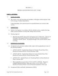
HORIZONTAL TANK <strong>INSTALLATION</strong><br />
Installation of horizontal tanks is much the same as the dished bottom. Tanks are supplied<br />
with the required number of steel support saddles. These saddles are to be placed under the<br />
designated support rings. The saddles must be centered on the support ring and through the<br />
centerline of the tank. Caution must be taken to insure that the tank support ring is in contact<br />
with each saddle.<br />
SUPPORT RING<br />
SADDLE<br />
150°<br />
SADDLE<br />
CONTACT<br />
AREA<br />
Caution: Modification of saddles in any way voids your warranty.<br />
Page 11
<strong>OPERATION</strong> AND <strong>MAINTENANCE</strong> <strong>INSTRUCTIONS</strong><br />
Because of FIBERGLASS REINFORCED PLASTIC tanks unique, physical and structural characteristics;<br />
they are flexible, lightweight, corrosion resistant, and stronger than tanks made of other plastic materials.<br />
Care, however, should be taken to follow the Handling and Installation instructions. Once the tank has been<br />
properly installed and placed in service, BTT recommends regular routine inspections as a part of your<br />
preventative maintenance program.<br />
The care and operation of FRP vessels rely mostly on common sense. To maximize trouble free service,<br />
Belding Tank recommends:<br />
1. Inspect your vessel thoroughly upon receipt.<br />
2. Follow the Handling and Installation instruction.<br />
3. Wash your vessel thoroughly w/detergent and rinse before putting in service (see FDA Requirements)<br />
AFTER THE TANK IS PUT IN SERVICE:<br />
1. Keep the vessel clean.<br />
a. It will remain more aesthetically pleasing.<br />
b. If the tank is ever damaged, it will be evident.<br />
2. Make a visual tank inspection inside and outside the tank every 6-12 months.<br />
TANKS FOR FOOD APPLICATION:<br />
BELDING TANK TECHNOLOGIES tanks will comply with U.S. Food, Drug and Cosmetic Act, as<br />
amended, and applicable FDA regulations (21 cfr 177.2420). These tanks may be used as components<br />
intended for repeated use in contact with food, subject to certain limitations described in that regulation.<br />
BELDING TANK TECHNOLOGIES tanks are chemically acceptable in processing or storage areas for<br />
contact with meat or poultry food products prepared under federal inspection and used at temperatures below<br />
250° F. This acceptance has been given by the United States Department of Agriculture.<br />
Prior to shipping your tank, B.T.T. applies a (4) hour heat cure followed by a hot water wash to the tank<br />
interior.<br />
After installation and before your tank is put into service, attention to the following procedures is important<br />
to achieve FDA compliance:<br />
1. After tank installation, steam-treat or steep tank with hot water for 8-16 hours at 160° – 180° F. This<br />
should remove all residual styrene from the laminate surface.<br />
2. Wash the tank thoroughly with detergent and rinse it thoroughly.<br />
3. Check state and local regulations for required compliance in addition to the above recommendations.<br />
Page 12
AIR LOADING<br />
<strong>OPERATION</strong> AND <strong>MAINTENANCE</strong> <strong>INSTRUCTIONS</strong><br />
“Tanks are often filled with liquids from tanker trucks by pressurizing the headspace above the liquid within<br />
the tanker with compressed air to force tanker contents into the receiving tank. This is most typically done<br />
when the liquid being transferred is a corrosive chemical, which could damage a pump. Although such a<br />
procedure eliminates the need for a pump, a possibility does exist that the pressurized air within the tanker<br />
will follow the liquid into the receiving tank, and destroy the tank, due to excessive pressure.<br />
Generally speaking, the tanker is connected to the receiving tank by a hose. The compressed air pushing<br />
down on the liquid forces the liquid through the hose and into the receiving tank. The frictional resistance<br />
offered by the hose and the fitting limits the maximum velocity of the liquid moving through the hose to a<br />
reasonable value. The air displaced by the liquid entering the tank escapes through the normal vent provided<br />
on the tank.<br />
However, when the last of the liquid passes through the hose, the compressed air within the tanker rushes<br />
through the hose at an extremely high velocity, because this air does not meet significant frictional resistance<br />
in the hose, as the liquid does. This air enters the headspace in the receiving tank and expands with almost<br />
explosive speed and force. The conventional tank vent cannot relive this excessive pressure within the tank.<br />
When the pressure within the receiving tank exceeds that for which the tank is designed, either the tank head<br />
blows off or some other portion of the tank ruptures.<br />
Preferably, the person operating the tanker will interrupt the liquid flow before the last of the liquid leaves<br />
the tanker, preventing the compressed air from entering the tank. However, through inattention or<br />
carelessness, the operator will occasionally forget to interrupt the liquid at the "appropriate<br />
time"…RESULT…POSSIBLE TANK FAILURE.”<br />
The quoted description above is the possible occurrence when the tank is air loaded…IMPROPERLY;<br />
proper procedure requires that the operator interrupt the liquid at the appropriate time. PROPER<br />
PROCEDURE WILL NOT CAUSE TANK FAILURE.<br />
To guard against tank failure when the tank is air loaded, opening the manhole cover is suggested. This<br />
precaution, if the tank is air loaded improperly, does NOT eliminate the possibility of tank failure…but it<br />
may lessen the possibility.<br />
TO ELIMINATE TANK FAILURE DUE TO IMPROPER AIR LOADING:<br />
A. BUILD A PRESSURE VESSEL, OR<br />
B. ELIMINATE THE POSSIBILITY OF THE AIR PAD PRESSURE IN THE TANKER FROM<br />
REACHING THE TANK EXTERIOR BY:<br />
1. Suspending the fill line above the manway (i.e. line is not to enter tank), OR…<br />
2. Monitoring a flow meter to determine when the tanker will be empty, OR…<br />
3. Install a "No-Flow" switch in tandem with a control valve.<br />
Note: B.T.T. recommends consulting with a reputable firm in reference to flow meters and no flow switches.<br />
If you have any questions or special circumstances that require discussion, please feel free to contact us at…<br />
1-800-253-4252.<br />
Page 13
<strong>OPERATION</strong> AND <strong>MAINTENANCE</strong> <strong>INSTRUCTIONS</strong><br />
BOLTING SEQUENCE<br />
Maximum Manhole Bolt Torque = 60 ft. lbs.<br />
Drawings not to scale<br />
Flanged Nozzle Maximum Bolt Torque<br />
Nozzle Size<br />
Bolt Torque<br />
1" - 12" 25 ft. lbs. max<br />
14" - 16" 30 ft. lbs. max.<br />
18" - 20" 35 ft. lbs. max<br />
24" 40 ft. lbs. max.<br />
Page 14
<strong>OPERATION</strong> AND <strong>MAINTENANCE</strong> <strong>INSTRUCTIONS</strong><br />
Flanged Nozzle Allowable Loads Without Gussets<br />
Size A B C<br />
1 30 LBS. 50 FT./LBS. 30 LBS.<br />
1-1/2 50 LBS. 50 FT./LBS. 50 LBS.<br />
2 50 LBS. 50 FT./LBS. 50 LBS.<br />
3 50 LBS. 50 FT./LBS. 50 LBS.<br />
4 50 LBS. 50 FT./LBS. 50 LBS.<br />
6 50 LBS. 50 FT./LBS. 50 LBS.<br />
8 100 LBS. 50 FT./LBS. 100 LBS.<br />
10 100 LBS. 50 FT./LBS. 100 LBS.<br />
12 100 LBS. 50 FT./LBS. 100 LBS.<br />
Page 15
<strong>OPERATION</strong> AND <strong>MAINTENANCE</strong> <strong>INSTRUCTIONS</strong><br />
TANK USAGE<br />
This tank has been sold for a specific chemical storage application. Before changing the<br />
chemical environment, consult with BELDING TANK TECHNOLOGIES (your warranty<br />
may be void without written authorization from B.T.T.)<br />
BELDING TANK standard tanks are NOT designed for pressure or vacuum other than liquid<br />
head. Be sure tanks are properly vented to avoid accidental pressure or vacuum.<br />
Page 16
STATEMENT OF WARRANTY<br />
Belding Tank Technologies, Inc. warrants its manufactured products against<br />
any defects in the material and workmanship only for a period of (12) months<br />
from shipment.<br />
In the event that the purchaser asserts and Belding Tank Technologies, Inc.<br />
agrees that the product is defective per this warranty, Belding Tank<br />
Technologies, Inc. may, at its election replace, repair or credit the customer,<br />
on the condition that the product is in possession of the original purchaser<br />
and the product has been used for its originally intended purpose and design.<br />
Any component parts that are on products manufactured and designed by<br />
Belding Tank, are warranted only to the extent of the manufacturer of each<br />
component part and to the extent as is enforceable by Belding Tank<br />
Technologies, Inc.<br />
Any alterations, modifications, or changes to any products manufactured or<br />
supplied by Belding Tank Technologies, Inc., automatically voids this<br />
warranty.<br />
No warranty, either expressed or implied, is made by Belding Tank<br />
Technologies, Inc. as to the fitness, merchantability, condition, capacity, or<br />
efficiency of any products or goods sold, and no claims for labor or for<br />
consequential damages will be allowed.<br />
If purchaser attempts to repair product or take any other action, prior to<br />
giving prompt notice and providing a reasonable opportunity for Belding<br />
Tank Technologies, Inc. to inspect and correct said product, as deemed<br />
necessary by the manufacturer, Belding Tank Technologies, Inc. shall not be<br />
held liable for any expenses incurred by the purchaser.<br />
No product may be returned for credit or replacement unless first authorized<br />
by Belding Tank Technologies, Inc.<br />
Belding Tank Technologies, Inc.’s liability and the purchaser’s exclusive<br />
remedies are limited to those set forth in this warranty, to the exclusion of all<br />
others.