Short and long-range visual navigation using warped panoramic ...
Short and long-range visual navigation using warped panoramic ...
Short and long-range visual navigation using warped panoramic ...

You also want an ePaper? Increase the reach of your titles
YUMPU automatically turns print PDFs into web optimized ePapers that Google loves.
sh<br />
sv<br />
3<br />
0<br />
-3<br />
0<br />
1<br />
0<br />
-1<br />
0<br />
90<br />
90<br />
180<br />
Column index<br />
Fig. 6. The functions used for the horizontal (top) <strong>and</strong> vertical<br />
(bottom) shifts of positions to obtain the top of the boundary used<br />
by the warping to simulate the forward translation. For the bottom<br />
part of the boundary, the same functions were used but inverting<br />
the column index.<br />
180<br />
Forward translation<br />
Right translation<br />
Fig. 7. The boundaries used by the warping to simulate the translations<br />
(solid) that map onto the image (dashed)<br />
Fig. 8. A pair of images used to determine the parameters of the<br />
warping <strong>and</strong> the result of the warping: Ic (top), Iδx (middle) <strong>and</strong> the<br />
simulation I ′ δx of Iδx (bottom). Vertical lines show the alignment of<br />
several features.<br />
of the gradient wrong, especially near the minimum of the<br />
distance between current <strong>and</strong> target images, leading to the<br />
systematic offset reported in (Binding <strong>and</strong> Labrosse, 2006).<br />
Figure 6 shows the resulting functions that were used to<br />
shift the boundary points. The sideways translation functions<br />
are the same as for the forward translation but shifted<br />
column-wise by 90 columns. Figure 7 shows the resulting<br />
boundaries used by the warping.<br />
Figure 8 shows an example of an image pair used to determine<br />
the warping parameters a<strong>long</strong> with the result of the<br />
warping of the first image of the pair. Vertical lines show<br />
the alignment of <strong>visual</strong> features of the images. This clearly<br />
shows that the pixels of the real <strong>and</strong> simulated translations<br />
align properly. Note that because the vertical shift is only<br />
of 1.2 pixels, the effect of this shift is only barely visible<br />
on Figure 7 <strong>and</strong> especially Figure 8. This has however a<br />
definitive impact on the computed gradient.<br />
270<br />
270<br />
360<br />
360<br />
5<br />
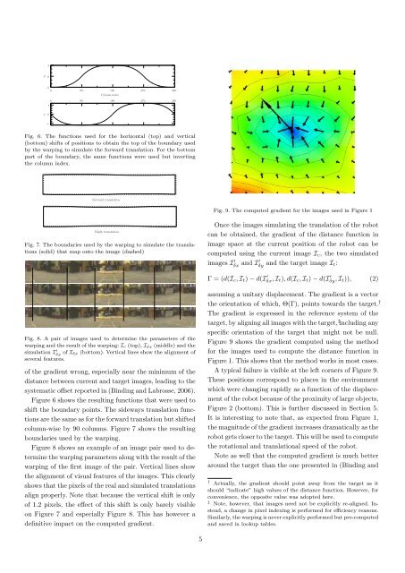
Fig. 9. The computed gradient for the images used in Figure 1<br />
Once the images simulating the translation of the robot<br />
can be obtained, the gradient of the distance function in<br />
image space at the current position of the robot can be<br />
computed <strong>using</strong> the current image Ic, the two simulated<br />
images I ′ δx <strong>and</strong> I′ δy <strong>and</strong> the target image It:<br />
Γ = (d(Ic, It) − d(I ′ δx, It), d(Ic, It) − d(I ′ δy, It)), (2)<br />
assuming a unitary displacement. The gradient is a vector<br />
the orientation of which, Θ(Γ), points towards the target. †<br />
The gradient is expressed in the reference system of the<br />
target, by aligning all images with the target, ‡ including any<br />
specific orientation of the target that might not be null.<br />
Figure 9 shows the gradient computed <strong>using</strong> the method<br />
for the images used to compute the distance function in<br />
Figure 1. This shows that the method works in most cases.<br />
A typical failure is visible at the left corners of Figure 9.<br />
These positions correspond to places in the environment<br />
which were changing rapidly as a function of the displacement<br />
of the robot because of the proximity of large objects,<br />
Figure 2 (bottom). This is further discussed in Section 5.<br />
It is interesting to note that, as expected from Figure 1,<br />
the magnitude of the gradient increases dramatically as the<br />
robot gets closer to the target. This will be used to compute<br />
the rotational <strong>and</strong> translational speed of the robot.<br />
Note as well that the computed gradient is much better<br />
around the target than the one presented in (Binding <strong>and</strong><br />
† Actually, the gradient should point away from the target as it<br />
should “indicate” high values of the distance function. However, for<br />
convenience, the opposite value was adopted here.<br />
‡ Note, however, that images need not be explicitly re-aligned. Instead,<br />
a change in pixel indexing is performed for efficiency reasons.<br />
Similarly, the warping is never explicitly performed but pre-computed<br />
<strong>and</strong> saved in lookup tables.