dBi Series ( )
SECOND EDITION - Pulsar Process Measurement
SECOND EDITION - Pulsar Process Measurement
- No tags were found...

Create successful ePaper yourself
Turn your PDF publications into a flip-book with our unique Google optimized e-Paper software.
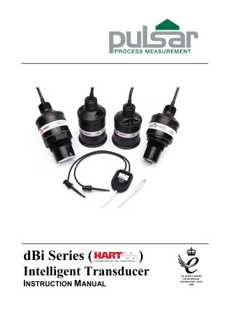
<strong>dBi</strong> <strong>Series</strong> ( )<br />
Intelligent Transducer<br />
INSTRUCTION MANUAL
<strong>dBi</strong> SERIES (HART) INTELLIGENT TRANSDUCER (FIRST EDITION REV 1)<br />
September 2012<br />
Part Number M-<strong>dBi</strong>-H-001-1P<br />
COPYRIGHT<br />
© Pulsar Process Measurement Limited, 2012. All rights reserved. No part of this publication may be<br />
reproduced, transmitted, transcribed, stored in a retrieval system, or translated into any language in<br />
any form without the written permission of Pulsar Process Measurement Limited.<br />
WARRANTY AND LIABILITY<br />
Pulsar Process Measurement Limited guarantee for a period of 2 years from the date of delivery that it<br />
will either exchange or repair any part of this product returned to Pulsar Process Measurement<br />
Limited if it is found to be defective in material or workmanship, subject to the defect not being due to<br />
unfair wear and tear, misuse, modification or alteration, accident, misapplication or negligence.<br />
DISCLAIMER<br />
Pulsar Process Measurement Limited gives nor implies any process guarantee for this product, and<br />
shall have no liability in respect of any loss, injury or damage whatsoever arising out of the<br />
application or use of any product or circuit described herein.<br />
Every effort has been made to ensure accuracy of this documentation, but Pulsar Process<br />
Measurement Limited cannot be held liable for any errors.<br />
Pulsar Process Measurement Limited operates a policy of constant development and improvement and<br />
reserves the right to amend technical details as necessary.<br />
TECHNICAL ENQUIRIES<br />
Please contact Pulsar Process Measurement Limited for technical support.<br />
COMMENTS AND SUGGESTIONS<br />
If you have any comments or suggestions about this product, then please contact:<br />
Pulsar Process Measurement Limited<br />
Cardinal Building<br />
Enigma Commercial Centre<br />
Sandy’s Road<br />
Malvern<br />
Worcestershire<br />
WR14 1JJ<br />
United Kingdom<br />
Tel: + 44 (0) 1684 891371<br />
Fax: + 44 (0) 1684 575985<br />
Web Site: http://www.pulsar-pm.com<br />
e-mail: info@pulsar-pm.com (general<br />
information)<br />
e-mail: support@ pulsar-pm.com (product<br />
support)<br />
Pulsar Process Measurement Inc.<br />
PO Box 5177<br />
Niceville<br />
FL 32578-5177<br />
USA<br />
Tel: + 1 850 279 4882<br />
Fax: + 1 850 279 4886<br />
Web Site: http://www.pulsar-pm.com<br />
e-mail: info.usa@pulsar-us.com (general<br />
information)<br />
e-mail: support.usa@ pulsar-pm.com (product<br />
support)
Contents<br />
Chapter 1 Start Here… ......................................................................................................................................... 1<br />
About this Manual ........................................................................................................................................... 1<br />
About the <strong>dBi</strong> <strong>Series</strong> (HART) Intelligent Transducer ................................................................................... 2<br />
Functional Description ............................................................................................................................ 2<br />
Product Specification....................................................................................................................................... 4<br />
Physical .................................................................................................................................................... 4<br />
Environmental.......................................................................................................................................... 4<br />
Performance ............................................................................................................................................. 5<br />
Communications Protocol ....................................................................................................................... 5<br />
PC interface .............................................................................................................................................. 5<br />
Chapter 2 Installation............................................................................................................................................ 9<br />
Power Supply Requirements ........................................................................................................................... 9<br />
Dimensions .................................................................................................................................................... 10<br />
The dimensions of the <strong>dBi</strong> <strong>Series</strong> Intelligent Transducer are as shown below. .......................................... 10<br />
Rear Thread Mount ............................................................................................................................... 10<br />
Front Thread Mount .............................................................................................................................. 11<br />
Outdoor and Open Vessel Installation .......................................................................................................... 12<br />
Closed Vessel Installation ............................................................................................................................. 13<br />
Stand Pipe Installations ......................................................................................................................... 13<br />
Cable .............................................................................................................................................................. 14<br />
Typical wiring for a Non-Hazardous location .............................................................................................. 15<br />
................................................................................................................................................................ 15<br />
Loop Resistance ..................................................................................................................................... 15<br />
Preparation for Operation .............................................................................................................................. 16<br />
Maintenance ................................................................................................................................................... 17<br />
Hazardous Area Installation .......................................................................................................................... 17<br />
Information specific to Hazardous Area Installation............................................................................ 17<br />
Hazardous Area specific Power Supply and barrier Requirements .................................................... 18<br />
Chapter 3 How To Use Your <strong>dBi</strong> <strong>Series</strong> Intelligent Transducer ..................................................................... 23<br />
4 – 20 mA Device .......................................................................................................................................... 23<br />
Accessing Parameters .................................................................................................................................... 24<br />
Hart Commands............................................................................................................................................. 24<br />
Universal ................................................................................................................................................ 24<br />
Common practice .................................................................................................................................. 24<br />
<strong>dBi</strong> Hart PC Lite ............................................................................................................................................ 24<br />
Connection ............................................................................................................................................. 26<br />
Configuration ......................................................................................................................................... 28<br />
Communication Port Configuration ..................................................................................................... 29<br />
Parameter Defaults ........................................................................................................................................ 30<br />
Factory Defaults ..................................................................................................................................... 30<br />
Chapter 4 Getting Results With Your <strong>dBi</strong> <strong>Series</strong> Intelligent Transducer ....................................................... 31<br />
Setting up Your Application ......................................................................................................................... 31<br />
Empty Distance...................................................................................................................................... 31<br />
Span ........................................................................................................................................................ 31<br />
Near and Far Blanking .......................................................................................................................... 31<br />
Using the 4-20 mA Output ............................................................................................................................ 31<br />
Setting Security Passcodes ............................................................................................................................ 32<br />
Changing The Passcode ........................................................................................................................ 32<br />
Resetting Factory Defaults ............................................................................................................................ 32<br />
Checking the Information Specific to your <strong>dBi</strong> <strong>Series</strong> Intelligent Transducer ........................................... 33
Checking the Software Revision and Serial Number .......................................................................... 33<br />
Chapter 5 Parameter Guide ................................................................................................................................ 35<br />
Parameter Listing ........................................................................................................................................... 35<br />
Application..................................................................................................................................................... 35<br />
Operation ................................................................................................................................................ 35<br />
P100 Mode of Operation ....................................................................................................................... 35<br />
P102 Material ......................................................................................................................................... 35<br />
Distances ................................................................................................................................................ 36<br />
P104 Measurement Units ...................................................................................................................... 36<br />
P105 Empty Level ................................................................................................................................. 36<br />
P106 Span .............................................................................................................................................. 36<br />
P107 Near Blanking Distance ............................................................................................................... 36<br />
P108 Far Blanking Distance ................................................................................................................. 37<br />
Data Logs ....................................................................................................................................................... 37<br />
Temperature ........................................................................................................................................... 37<br />
P580 Minimum Temperature ................................................................................................................ 37<br />
P581 Minimum Temperature Date ....................................................................................................... 37<br />
P582 Minimum Temperature Time ...................................................................................................... 37<br />
P583 Maximum Temperature ............................................................................................................... 37<br />
P584 Maximum Temperature Date ...................................................................................................... 37<br />
P585 Maximum Temperature Time ..................................................................................................... 37<br />
P586 Current Temperature .................................................................................................................... 38<br />
Transducer Power Information ............................................................................................................. 38<br />
P940 Number of Starts .......................................................................................................................... 38<br />
P941 Last Power Off Date .................................................................................................................... 38<br />
P942 Last Power Off Time ................................................................................................................... 38<br />
P943 Last Run Time (minutes) ............................................................................................................. 38<br />
P944 Last Run Time (hours) ................................................................................................................. 38<br />
P945 Total Runtime (hours) .................................................................................................................. 38<br />
Volume........................................................................................................................................................... 39<br />
Conversion ............................................................................................................................................. 39<br />
P600 Vessel Shape ................................................................................................................................ 39<br />
P601-P603 Vessel Dimensions ............................................................................................................. 41<br />
P604 Calculated Volume....................................................................................................................... 41<br />
P605 Volume Units ............................................................................................................................... 42<br />
P606 Correction Factor ......................................................................................................................... 42<br />
P607 Max Volume ................................................................................................................................ 42<br />
Breakpoints ............................................................................................................................................ 43<br />
P610-P641 Level/Volume Breakpoints ................................................................................................ 43<br />
P696 Reset Breakpoints ........................................................................................................................ 44<br />
P697 Number of Breakpoints Set ........................................................................................................ 44<br />
mA Output ..................................................................................................................................................... 45<br />
P834 mA Low Level ............................................................................................................................. 45<br />
P835 mA High Level ............................................................................................................................ 45<br />
P838 mA Low Trim .............................................................................................................................. 45<br />
P839 mA High Trim .............................................................................................................................. 45<br />
P808 Fail-safe Mode ............................................................................................................................. 45<br />
P809 Fail-safe Time .............................................................................................................................. 46<br />
Compensation ................................................................................................................................................ 46<br />
P851 Measurement Offset ..................................................................................................................... 46<br />
P852 Temperature Source ..................................................................................................................... 46<br />
P854 Fixed Temperature ....................................................................................................................... 46<br />
P860 Sound Velocity ............................................................................................................................. 47<br />
P645 Vapour Temperature Compensation ........................................................................................... 47<br />
Stability .......................................................................................................................................................... 48<br />
Damping................................................................................................................................................. 48
P870 Fill Damping ................................................................................................................................ 48<br />
P871 Empty Damping ........................................................................................................................... 48<br />
Filters ...................................................................................................................................................... 48<br />
P881 Fixed Distance .............................................................................................................................. 48<br />
P884 Peak Percentage ........................................................................................................................... 48<br />
System ............................................................................................................................................................ 48<br />
Password ................................................................................................................................................ 49<br />
P921 Enable Code ................................................................................................................................. 49<br />
P922 Passcode ....................................................................................................................................... 49<br />
System Information ............................................................................................................................... 49<br />
P926 Software Revision ........................................................................................................................ 49<br />
P927 Hardware Revision....................................................................................................................... 49<br />
P928 Serial Number .............................................................................................................................. 49<br />
P930 Factory Defaults ........................................................................................................................... 49<br />
Date & Time .......................................................................................................................................... 49<br />
P931 Date ............................................................................................................................................... 49<br />
P932 Time .............................................................................................................................................. 49<br />
LOE Save Trace .................................................................................................................................... 50<br />
P950 Save DATEM Trace on LOE ...................................................................................................... 50<br />
DATEM ......................................................................................................................................................... 50<br />
P020 Set DATEM ................................................................................................................................. 50<br />
P021 Set Dist ......................................................................................................................................... 50<br />
P905 Peak Clearance ............................................................................................................................. 51<br />
P906 Side Clearance .............................................................................................................................. 51<br />
Chapter 6 Troubleshooting ................................................................................................................................ 53<br />
Parameter Record ................................................................................................................................................. 54
Chapter 1<br />
Start Here…<br />
Congratulations on your purchase of a Pulsar <strong>dBi</strong> <strong>Series</strong> Intelligent<br />
Transducer Level Monitoring System. This quality system has been<br />
developed over many years and represents the latest in high technology<br />
ultrasonic level measurement and control. It has been designed to give you<br />
years of trouble-free performance, and a few minutes spent reading this<br />
operating manual will ensure that your installation is as simple as possible.<br />
About this Manual<br />
It is important that this manual is referred to for correct installation and<br />
operation.<br />
There are various parts of the manual that offer additional help or<br />
information as shown:<br />
TIP<br />
Tips<br />
At various parts of this manual you will find tips to<br />
help you.<br />
Additional Information<br />
Additional Information<br />
At various parts of the manual, you will find sections<br />
like this that explain specific items in more detail.<br />
Page1
About the <strong>dBi</strong> <strong>Series</strong> (HART) Intelligent Transducer<br />
Functional Description<br />
The <strong>dBi</strong> <strong>Series</strong> Intelligent Transducer is a highly developed ultrasonic<br />
level measurement system which provides non-contacting level<br />
measurement for a wide variety of applications in both liquids and solids. Its<br />
unique design gives unrivalled performance in echo discrimination and<br />
accuracy in a loop powered device.<br />
Easy calibration and maintenance free “fit and forget” performance mean<br />
that you can install the <strong>dBi</strong> <strong>Series</strong> Intelligent Transducer Level<br />
Monitoring System rapidly and with confidence, with calibration being<br />
achieved either by the use of a HART programmer/calibrator or via a PC<br />
utilising the Pulsar interface and software.<br />
Page 2
The <strong>dBi</strong> <strong>Series</strong> Intelligent Transducer operates on the principle of timing<br />
the echo received from a measured pulse of sound transmitted in air and<br />
utilises “state of the art” echo extraction technology.<br />
<strong>dBi</strong> <strong>Series</strong> Intelligent Transducer comes in four models:<br />
<strong>dBi</strong> 3 with a range from 0.125m (0.41 feet) to 3.00m (9.84 feet), <strong>dBi</strong> 6 with<br />
a range of 0.3m (0.98 feet) to 6.00m (19.69 feet), and <strong>dBi</strong> 10 with a range of<br />
0.3m (0.98 feet) to 10.00m (32.81 feet) and <strong>dBi</strong> 15 with a range of 0.5m<br />
(1.64 feet) to 15.00m (49.213 feet).<br />
All models can be mounted via a rear, 1” BSP/NPT, thread (Standard) with<br />
a model with alternative front thread mounting being available, in addition<br />
flange mount and PVDF options are also available. See Chapter 2<br />
Installation for further details.<br />
All model types are available for use in hazardous area installations with<br />
either Ex mb or Ex ia ATEX certification.<br />
The <strong>dBi</strong> <strong>Series</strong> Intelligent Transducer has a 4 to 20mA output which can<br />
be programmed to give an output proportional to level, space, distance or<br />
volume, dependant on the measurement mode selected and provides a ‘fault<br />
condition’ alarm of either 3.8mA or 22mA.<br />
Page3
Product Specification<br />
Physical<br />
Model<br />
Housing<br />
Material<br />
Mounting<br />
Connection<br />
Overall<br />
Diameter<br />
Overall<br />
Height<br />
Nominal<br />
Weight<br />
<strong>dBi</strong> 3 metre Valox<br />
357 PBT<br />
Rear<br />
1″ BSP or NPT<br />
<strong>dBi</strong> 6 metre Valox Rear<br />
357 PBT 1″ BSP or NPT<br />
<strong>dBi</strong> 10 metre Valox Rear<br />
357 PBT 1″ BSP or NPT<br />
<strong>dBi</strong> 15 metre Valox Rear<br />
357 PBT 1″ BSP or NPT<br />
<strong>dBi</strong> 3 metre Valox Front<br />
357 PBT 1½″ Thread<br />
<strong>dBi</strong> 6 metre Valox Front<br />
357 PBT 1½″ Thread<br />
<strong>dBi</strong> 10 metre Valox Front<br />
357 PBT 2″ Thread<br />
<strong>dBi</strong> 3 metre PVDF Rear<br />
1″ BSP or NPT<br />
<strong>dBi</strong> 6 metre PVDF Rear<br />
1″ BSP or NPT<br />
<strong>dBi</strong> 10 metre PVDF Rear<br />
1″ BSP or NPT<br />
<strong>dBi</strong> 15 metre PVDF Rear<br />
1″ BSP or NPT<br />
<strong>dBi</strong> 3 metre PVDF Front<br />
1½″ Thread<br />
<strong>dBi</strong> 6 metre PVDF Front<br />
1½″ Thread<br />
<strong>dBi</strong> 10 metre PVDF Front<br />
2″ Thread<br />
77 mm<br />
(3 inches)<br />
86 mm<br />
(3.4 inches)<br />
86 mm<br />
(3.4 inches)<br />
86mm<br />
(3.4 inches)<br />
77mm<br />
(3 inches)<br />
77mm<br />
(3 inches)<br />
77mm<br />
(3 inches)<br />
77 mm<br />
(3 inches)<br />
86 mm<br />
(3.4 inches)<br />
86 mm<br />
(3.4 inches)<br />
86mm<br />
(3.4 inches)<br />
77mm<br />
(3 inches)<br />
77mm<br />
(3 inches)<br />
77mm<br />
(3 inches)<br />
134 mm<br />
(5.3 inches)<br />
121 mm<br />
(4.8 inches)<br />
121 mm<br />
(4.8 inches)<br />
135mm<br />
(5.3 inches)<br />
160mm<br />
(6.3 inches)<br />
160mm<br />
(6.3 inches)<br />
160mm<br />
(6.3 inches)<br />
134 mm<br />
(5.3 inches)<br />
121 mm<br />
(4.8 inches)<br />
121 mm<br />
(4.8 inches)<br />
135mm<br />
(5.3 inches)<br />
160mm<br />
(6.3 inches)<br />
160mm<br />
(6.3 inches)<br />
160mm<br />
(6.3 inches)<br />
1.0Kg<br />
1.2Kg<br />
1.3Kg<br />
1.4Kg<br />
1.0Kg<br />
1.2Kg<br />
1.3Kg<br />
1.0Kg<br />
1.2Kg<br />
1.3Kg<br />
1.4Kg<br />
1.0Kg<br />
1.2Kg<br />
1.3Kg<br />
Environmental<br />
o Temperature range -40 to +80°C. Ambient Electronics<br />
o Temperature range -40 to +80°C. Transducer in process<br />
o IP rating IP68<br />
Page 4
Performance<br />
o Digital signal processing<br />
o Input Voltage range 10-28volts DC.<br />
o Frequencey<br />
<strong>dBi</strong> 3 125KHz<br />
<strong>dBi</strong> 6 75Khz<br />
<strong>dBi</strong> 10 50Khz<br />
<strong>dBi</strong> 15 41Khz<br />
o Beam Angle<br />
<strong>dBi</strong> 3, 6and 10
We, the undersigned:<br />
EC DECLARATION OF CONFORMITY<br />
Declaration No. 001001<br />
Name of Manufacturer<br />
/ Authorised<br />
representative<br />
Address:<br />
Country:<br />
Pulsar Process Measurement Ltd.<br />
Pulsar Process Measurement Ltd<br />
Cardinal Building<br />
Enigma Commercial Centre<br />
Sandy's Road<br />
Malvern<br />
Worcestershire<br />
WR14 1JJ<br />
England<br />
Declare under our sole responsibility that the following apparatus:<br />
Product description:<br />
Model or Type No.:<br />
Brand name:<br />
Ultrasonic Transducers, HART <strong>dBi</strong> range<br />
<strong>dBi</strong> 3, <strong>dBi</strong> 6, <strong>dBi</strong> 10 & <strong>dBi</strong> 15 Ex ia & Ex mb versions<br />
HART <strong>dBi</strong> range<br />
Are in conformity with the following relevant EC legislation:<br />
ATEX directive 94/9/EC<br />
EMC directive 2004/108/EC<br />
Based on the following harmonised standards:<br />
EN60079-0:2009<br />
EN60079-18:2009 (Ex mb)<br />
EN60079-11:2012 (Ex ia)<br />
EN60079-26:2007 (Ex ia)<br />
EN61326-1:2006<br />
EN55011 Class B<br />
radiated emissions<br />
EN61000-4-2 Level 4 Immunity to static discharge<br />
EN61000-4-3 Immunity to radiated fields EN61000-4-5 Level 4<br />
immunity to surges<br />
EN61000-4-6 Level 4 immunity to conducted interference<br />
Page 6
And therefore complies with all of the relevant essential requirements of<br />
those other directives.<br />
The following Notified Body has been involved in the conformity<br />
assessment process:<br />
Notified Body TRaC Global Ltd<br />
Notified Body No. 0891<br />
Role:<br />
Issue of ATEX EC Type Examination certificate<br />
Certificate No. TRaC12ATEX0022X (Ex ia) & TRaC12ATEX0023X (Ex<br />
mb)<br />
(Additional information:<br />
ATEX coding<br />
II 1 G Ex ia IIC T4 Ga & II 1 D Ex ia IIIC T130°C Da<br />
Tamb -40°C to +80°C<br />
II 2 G Ex mb IIC T4 Gb & II 2 D Ex mb IIIC T130°C Db<br />
Tamb -40°C to +80°C<br />
Limitations on use 1. The <strong>dBi</strong> transducers must be routinely inspected to avoid<br />
the build up of dust layers when installed in a Zone 21 &<br />
22.<br />
2. Electrostatic hazard – The <strong>dBi</strong> transducers must only be<br />
wiped with a damp or antistatic cloth<br />
3. Only the fuses listed on drawing D-0804-0978-A are<br />
permitted to be used with the Ex approved <strong>dBi</strong> transducers.<br />
Name and position of person binding the manufacturer or authorised<br />
representative:<br />
Signature<br />
Name<br />
Steve Lycett<br />
Function<br />
Authorised Person<br />
Location<br />
Pulsar Process Measurement Ltd, WR14 1JJ<br />
Date of issue 2012-11-09<br />
Page7
Page 8<br />
This page left blank intentionally
Chapter 2<br />
Installation<br />
Power Supply Requirements<br />
The <strong>dBi</strong> <strong>Series</strong> Intelligent Transducer operates from a DC supply of 10 to<br />
28V and will typically draw less than 22mA.<br />
All electronic products are susceptible to electrostatic<br />
shock, so follow proper grounding procedures during<br />
installation.<br />
The compact one-piece construction of the <strong>dBi</strong> <strong>Series</strong> Intelligent<br />
Transducer can be mounted easily using either the 1″BSP/NPT rear<br />
mounting thread or the integral 1.5" or 2" BSP/ NPT, nose thread, dependent<br />
on model.<br />
When choosing a location to mount the <strong>dBi</strong> <strong>Series</strong> Intelligent Transducer,<br />
bear in mind the following:<br />
The ultrasonic signal path should be free of falling material and<br />
obstructions such as pipes, beams etc.<br />
The <strong>dBi</strong> 3 should be mounted at least 12.5cm (0.41 feet) above the<br />
maximum level of the material and be perpendicular to the surface.<br />
While the <strong>dBi</strong> 6 and 10 should be mounted at least 30cm (0.98 feet)<br />
above the maximum level of the material and be perpendicular to<br />
the surface. And the <strong>dBi</strong> 15 should be mounted at least 50cm (1.64<br />
feet) above the maximum level of the material and again should be<br />
perpendicular to the surface<br />
The ambient temperature is between -40ºC and 80ºC.<br />
There should be no high voltage cables or electrical inverter wiring<br />
in close proximity to the transducer cabling.<br />
Page9
Dimensions<br />
The dimensions of the <strong>dBi</strong> <strong>Series</strong> Intelligent Transducer are as shown below.<br />
Rear Thread Mount<br />
<strong>dBi</strong> 3 <strong>dBi</strong> 6 & 10<br />
<strong>dBi</strong> 15<br />
Page 10
Front Thread Mount<br />
<strong>dBi</strong> 3 & 6 <strong>dBi</strong> 10<br />
Page11
Outdoor and Open Vessel Installation<br />
The <strong>dBi</strong> <strong>Series</strong> Intelligent Transducer can be simply mounted on a<br />
bracket, suitable for the application and secured using either the 1"<br />
BSP/NPT rear thread or via the 1½″ or 2″ front thread, dependant on model.<br />
Care should be taken to ensure that the <strong>dBi</strong> <strong>Series</strong> Intelligent Transducer<br />
is not installed in direct sunlight, in order to avoid errors in the measurement<br />
of ambient temperature.<br />
Attention should also be taken, when mounting the unit, to ensure that<br />
strong windy conditions are avoided, wherever possible, to prevent<br />
abnormal operation.<br />
<strong>dBi</strong> Model Range L = Blanking<br />
<strong>dBi</strong> 3 3 metres (9.84 feet) 125mm (0.41 feet)<br />
<strong>dBi</strong> 6 6 metres (19.69 feet) 300mm (0.98 feet)<br />
<strong>dBi</strong> 10 10 metres (32.18 feet) 300mm (0.98 feet)<br />
<strong>dBi</strong> 15 15 metres (49.21 feet) 500mm (1.64 feet)<br />
‘L’ (Blanking) should as a minimum be at least that as detailed in the<br />
table above, but can be greater if required.<br />
Mounted via Rear 1″BSP?NPT<br />
Thread<br />
Mounted via optional Front Thread<br />
Page 12
Closed Vessel Installation<br />
“L” should as a minimum be at least that as detailed in the table above, but<br />
can be greater if required. The <strong>dBi</strong> <strong>Series</strong> Intelligent Transducer can be<br />
simply screwed into a flange and secured using the rear 1" BSP/NPT rear<br />
thread or via the 1½″ or 2″ front thread, dependant on model.<br />
Where possible use a flange made of a synthetic material such as PVC, in<br />
cases where a metal flange is used it is advisable to fit a suitable gasket<br />
between the flange of the <strong>dBi</strong> <strong>Series</strong> Intelligent Transducer and the<br />
connection to the vessel.<br />
Stand Pipe Installations<br />
When mounting the <strong>dBi</strong> <strong>Series</strong> Intelligent Transducer to a standpipe care<br />
should be taken to ensure that the standpipe is of sufficient diameter with<br />
reference to its length, see the table below for details:<br />
Dia. (D)<br />
Max Length (L)<br />
mm inches mm inches<br />
80 3 220 8<br />
100 4 300 12<br />
150 6 420 16<br />
200 8 560 22<br />
<strong>dBi</strong> Flange mounted via Front Thread<br />
Optional Flange Mounted <strong>dBi</strong><br />
Page13
When using a standpipe, fixed to the top of a vessel, ensure that the open<br />
end of the standpipe is clear of any obstructions such as weld seams, gaskets<br />
etc. in order to avoid unwanted signal returns.<br />
If using standpipes which extend in to the vessel, beyond the blanking<br />
distance, but not as far as the empty level, then the open end of the standpipe<br />
should be cut to an angle of 45 o .<br />
The maximum<br />
level (100% of<br />
Span) is inside the<br />
Blanking Distance<br />
Pipe should be free<br />
of obstructions<br />
such as weld seams<br />
Correct<br />
standpipe<br />
installation<br />
Cable<br />
When using the <strong>dBi</strong> <strong>Series</strong> Intelligent Transducer to measure ‘aggressive,<br />
materials such as ‘alkaline’ and ‘acids’ it is recommended that either a<br />
PVDF or an optional PTFE faced Flanged Transducer is used. Please<br />
consult Pulsar for full availability of options.<br />
The <strong>dBi</strong> <strong>Series</strong> Intelligent Transducer comes with a fitted integral cable, if<br />
this cable is extended then the total capacitance must not exceed the limits<br />
for the voltage applied.<br />
Important Information<br />
In the case of the Ex mb version the cable is fitted with an over<br />
current protection device in the form of a fuse, please note that<br />
under no circumstances should this fuse be removed. The fuse<br />
must be fitted in the non-hazardous area,<br />
Page 14
Typical wiring for a Non-Hazardous location<br />
The HART modem and PC or HART programmer are used to set up the operation<br />
parameters for the <strong>dBi</strong> transducer. The output can either be as a 4-20mA current<br />
giving level or distance or as a digital signal via a HART master.<br />
The <strong>dBi</strong> transducers cable is a twisted pair with overall cable screen. The twisted<br />
pair are red and black, connect the red to +ve and the black to –ve. The screen<br />
should go to signal ground.<br />
Loop Resistance<br />
For two wire operation the maximum cable resistance allowable can be calculated<br />
from the graph below. For example if an <strong>dBi</strong> <strong>Series</strong> Intelligent Transducer was<br />
supplied from 24V, the maximum total cable resistance is 600 ohms, for a typical<br />
77 ohm /km cable this would mean a maximum cable length of 600/77 = 7.8km,<br />
remember this total cable resistance, so this figure has to be divided by 2 to give<br />
3.9km max distance.<br />
Page15
Maximum cable resistance vs supply voltage.<br />
Important Information<br />
If the equipment is installed or used in a manner not specified in this<br />
manual, then the protection provided by the equipment may be impaired.<br />
Preparation for Operation<br />
Before switching on, check the following:<br />
The <strong>dBi</strong> <strong>Series</strong> Intelligent Transducer is mounted correctly.<br />
The power supply is correctly installed.<br />
Page 16
Maintenance<br />
There is no user serviceable parts inside your <strong>dBi</strong> <strong>Series</strong> Intelligent<br />
Transducer, if you experience any problems with the unit, then please<br />
contact Pulsar Process Measurement for advice.<br />
To clean the equipment, wipe with a damp cloth. Do not use any solvents on<br />
the enclosure.<br />
Hazardous Area Installation<br />
Information specific to Hazardous Area Installation<br />
(Reference European ATEX Directive 94/9/EC, Annex II, 1.0.6.)<br />
The following instructions apply to equipment covered by certificate number<br />
TRAC 12ATEX0022X (Ex ia) & TRAC 12ATEX0023X (Ex mb)<br />
1. The equipment may be used with flammable gases and vapours with<br />
apparatus groups IIC, IIB, and IIA with temperature classes; T1, T2, T3,<br />
T4 maximum ambient temperature range -40 o C to +80 o C.<br />
2. The equipment is only certified for use in ambient temperatures in the<br />
range -40 o C to +80 o C and should not be used outside this range<br />
3. Installation shall be carried out in accordance with the applicable code of<br />
practice by suitably-trained personnel<br />
4. Repair of this equipment shall be carried out in accordance with the<br />
applicable code of practice.<br />
5. Certification marking as detailed in drawing number<br />
D-804-0957-B (Ex ia) & D-804-0994-A (Ex mb).<br />
6. If the equipment is likely to come into contact with aggressive<br />
substances, then it is the responsibility of the user to take suitable<br />
precautions that prevent it from being adversely affected, thus ensuring<br />
that the type of protection is not compromised.<br />
Aggressive Substances - e.g. acidic liquids or gases that may attack<br />
metals or solvents that may affect polymeric materials.<br />
Suitable Precautions - e.g. regular checks as part of routine inspections<br />
or establishing from the material’s data sheet that it is resistant to<br />
specific chemicals.<br />
Page17
7. The certificate number has an ‘X’ suffix that indicates that the following<br />
special condition of certification applies;<br />
In the case of <strong>dBi</strong> transducer range due to the housing and labels being<br />
non-conductive plastic care needs to be taken with regards electrostatic<br />
charge. The equipment shall not be installed if the conditions are<br />
conducive to the build up of electrostatic charge. Additionally the<br />
equipment should only be cleaned with a damp cloth.<br />
With the <strong>dBi</strong> Ex mb version a 100mA, 1500A breaking capacity fuse<br />
must be fitted in the positive lead of the cable. The product is shipped<br />
with this fuse in the cable, visible through the heat shrink at the wire end<br />
of the cable<br />
8. The manufacturer should note that, on being put into service, the<br />
equipment must be accompanied by a translation of the instructions in<br />
the language or languages of the country in which the equipment is to be<br />
used and by the instructions in the original language.<br />
Hazardous Area specific Power Supply and barrier Requirements<br />
The <strong>dBi</strong> transducer operates from a DC supply of 10 –28V and will typically<br />
draw less than 22mA.<br />
In the case of the Ex ia version the unit must be powered from an<br />
approved i.s. safety barrier or approved i.s. Power supply with the<br />
following limits:<br />
Uo
The <strong>dBi</strong> transducers cable is a twisted pair with overall cable screen. The<br />
twisted pair are red and black, connect the red to +ve and the black to –ve.<br />
The screen should go to signal ground.<br />
Typical wiring for the two types of <strong>dBi</strong> transducers:<br />
Page19
Page 20
Page21
Page 22
Chapter 3<br />
How To Use Your <strong>dBi</strong> <strong>Series</strong> Intelligent Transducer<br />
4 – 20 mA Device<br />
The <strong>dBi</strong> Hart Intelligent Transducer can be used as an ‘out of the box’ 4 –<br />
20mA device if this is the case then by default, when you switch the <strong>dBi</strong><br />
<strong>Series</strong> Intelligent Transducer on, the 4 – 20mA output will be proportional<br />
to the level being seen, with respect to the maximum range and span of the<br />
<strong>dBi</strong> model being used as detailed in the table below.<br />
4 mA (Empty)<br />
0% of Span<br />
Distance from <strong>dBi</strong><br />
Face in metres<br />
20 mA (Full)<br />
100% of Span<br />
Distance from <strong>dBi</strong><br />
Face in metres<br />
<strong>dBi</strong> 3 <strong>dBi</strong> 6 <strong>dBi</strong> 10 <strong>dBi</strong> 15<br />
3.000 6.000 10.000 15.000<br />
0.125 0.300 0.300 0.500<br />
Note<br />
Customised factory calibration of Span is available; please contact Pulsar for<br />
further details.<br />
Important Information<br />
When the <strong>dBi</strong> <strong>Series</strong> Intelligent Transducer is operated below 8mA then the<br />
speed of response will decrease. See the following table for cycle times:<br />
Page23
Time in seconds between firing<br />
For example – if using a <strong>dBi</strong> 6 and the target is causing a current draw of<br />
5mA then the cycle time (the time between measurements is 2 seconds.<br />
Any transducer drawing 9mA or above will have a cycle time of 1 second.<br />
Accessing Parameters<br />
In order to view or change parameters values one of the following methods<br />
must be used:<br />
Hart Commands<br />
If familiar with the use of HART protocol and the <strong>dBi</strong> <strong>Series</strong> Intelligent<br />
Transducer is connected to a HART modem then it can be programmed<br />
following normal HART procedures.<br />
Commands implemented by the <strong>dBi</strong> <strong>Series</strong> Intelligent Transducer are as<br />
follows:<br />
Universal<br />
0, 1, 2, 3, 6, 7, 8, 9, 11, 12, 13, 14, 15, 16, 17, 18, 19, 20, 21, 22, 38 and 48.<br />
Common practice<br />
33, 34, 35, 40, 41, 42, 45, 46, 47, 83, 89, 90, 111, 112 and 122.<br />
<strong>dBi</strong> Hart PC Lite<br />
Your <strong>dBi</strong> <strong>Series</strong> Intelligent Transducer comes complete with the dBI<br />
HART PC Lite software contained on CD, which, when used with a HART<br />
Modem, see Chapter 2 Installation for full details on how to connect the<br />
modem, can be used to to carry out the programming of the <strong>dBi</strong> <strong>Series</strong><br />
Intelligent Transducer.<br />
Page 24
Insert the CD into the CD drive of the PC intended to be used to carry out<br />
the programming of the <strong>dBi</strong> <strong>Series</strong> Intelligent Transducer and install the<br />
software, following the on screen instructions.<br />
Once the software is installed connect the computer via a convenient USB<br />
port to the HART Modem. Double click the ‘<strong>dBi</strong> HART PC Lite’ icon,<br />
installed on your desktop and the programme will open and you will see the<br />
following screen:<br />
Page25
To connect to the <strong>dBi</strong> <strong>Series</strong> Intelligent Transducer ‘click’ on the ‘Search’<br />
button which will then change to ‘Scanning’ and once a connection with a<br />
device has been established it will change to ‘Connected’ and the ‘Status’<br />
button will show ‘Connected’ and flash Green, if the <strong>dBi</strong> HART PC Lite<br />
fails to connect please check the Comport Configuration as detailed on page<br />
29. When using the <strong>dBi</strong> HART PC Lite software, keypad input can be<br />
achieved by using a ‘mouse’ or similar device to place the cursor over the<br />
relevant key followed by a ‘left’ click, with numeric detail being entered<br />
directly from the PC keyboard.<br />
Once <strong>dBi</strong> HART PC Lite has successfully connected you will see the<br />
following display:<br />
Connection<br />
Page 26
On the opening screen the following Information is available:<br />
Live List<br />
Gives details of all devices connected, if more than one device is present the<br />
‘Live List’ will become a drop down box and the required device selected.<br />
Poll Address<br />
Gives the Poll Address of the selected Device.<br />
Level<br />
Gives value of the Level in the vessel in Measurement Units (P104)<br />
mA %<br />
Gives current value of the mA Output and how full the vessel is in<br />
percentage.<br />
Set Empty Distance<br />
Allows the Empty Distance to be set.<br />
Set Span<br />
Allows the Span to be set which will determine the range of the 4 to 20mA<br />
output, with 4mA representing 0% (empty) and 20mA representing 100%<br />
(full).<br />
Range<br />
Shows the maximum range that can be measured, by the <strong>dBi</strong> <strong>Series</strong><br />
Intelligent Transducer, that is currently connected.<br />
Bar Graph Display<br />
Gives a graphical indication of the Empty Distance (P105) and Maximum<br />
Span (P106) along with current level being measured.<br />
Page27
Configuration<br />
Parameter Get/Set<br />
Get:<br />
Will read and display the current value of the parameter selected along with<br />
the ‘units’ of measurement, where used, and the description of the parameter<br />
selected. Select the desired parameter form the drop down ‘Parameter’ box<br />
and ‘click’ ‘Get’<br />
Page 28
Set:<br />
Allows the value of the selected parameter to be changed. Select the desired<br />
parameter form the drop down ‘Parameter’ box enter required value in the<br />
‘Value’ box and ‘click’ ‘Set’<br />
For a full list of available parameters see Chapter 5 Parameter Guide.<br />
4 – 20mA Trim<br />
If the device connected to the mA output is out of calibration, and cannot be<br />
calibrated, then the low and high current levels can be trimmed by altering<br />
Set 4mA (P838Low Trim) and Set 20mA (P839 High Trim). To do this,<br />
simply enter the value that ensures that 4 mA or 20 mA respectively are<br />
shown on the remote device.<br />
Communication Port Configuration<br />
If the <strong>dBi</strong> HART PC Lite fails to connect to the <strong>dBi</strong> <strong>Series</strong> Intelligent<br />
Transducer you may need to change the communications port that is being<br />
used, to do this ‘click’ on the ‘Comport’ menu in the top menu bar and the<br />
‘Comm Port Setup’ window will appear, select the appropriate<br />
communications port and then close the window.<br />
Page29
Parameter Defaults<br />
Factory Defaults<br />
Factory Defaults<br />
When first installing the <strong>dBi</strong> <strong>Series</strong> Intelligent Transducer, or subsequently<br />
moving or using the unit on a new application, before proceeding to program<br />
the unit for its intended application it is recommended that you ensure that all<br />
parameters are at their default values by completing a Factory Defaults<br />
P930, as described in Chapter 5 Parameter Guide.<br />
Once you are satisfied with the installation, and the <strong>dBi</strong> <strong>Series</strong> Intelligent<br />
Transducer is reading what you would expect in terms of distance from the<br />
face of the transducer to the material level, then you can proceed with any<br />
programming, required for the intended application. It is sensible to program<br />
all of the required parameters at the same time. The system will be then setup.<br />
Page 30
Chapter 4<br />
Getting Results With Your <strong>dBi</strong> <strong>Series</strong> Intelligent<br />
Transducer<br />
This chapter explains how to undertake the various functions of your <strong>dBi</strong><br />
<strong>Series</strong> Intelligent Transducer. Where specific parameters are used, consult<br />
Parameter Guide in Chapter 5.<br />
Setting up Your Application<br />
Empty Distance<br />
Empty Distance (P105) is the distance from the face of the transducer to<br />
the material at the bottom of the vessel.<br />
Span<br />
Span (P106) is the distance from the empty level (0% full) to span (100%<br />
full).<br />
Near and Far Blanking<br />
Near blanking (P107) is the distance from the face of the transducer that<br />
the <strong>dBi</strong> <strong>Series</strong> Intelligent Transducer will not record a level nearer than. A<br />
typical reason to increase this from the default value would be if you wish to<br />
ignore close in obstructions.<br />
Far blanking (P108) is the distance (as a percentage of empty level) beyond<br />
the empty level that the <strong>dBi</strong> <strong>Series</strong> Intelligent Transducer will read, the<br />
default is plus 20% of empty level. If you wish to monitor further than the<br />
empty level, then increase this figure, so that the empty level plus the far<br />
blanking figure (as % of empty level) is greater than the surface being<br />
measured, within the capability of the transducer being used.<br />
Using the 4-20 mA Output<br />
The mA output can be used to monitor remotely what the <strong>dBi</strong> <strong>Series</strong><br />
Intelligent Transducer is measuring, so it can be displayed remotely,<br />
integrated into a PLC, or used to generate a record using a chart recorder or<br />
similar.<br />
By default, the <strong>dBi</strong> <strong>Series</strong> Intelligent Transducer will provide a 4-20 mA<br />
output that is proportional to level and can be overwritten as follows.<br />
Page31
By default, the 4-20 mA will represent the operational span of the <strong>dBi</strong><br />
model in use, with empty (0% full) = 4mA and full (100% of the operational<br />
span) = 20mA, but you may wish to only represent a section of the<br />
operational span. For example, the application may have an operational span<br />
of 6 metres, but you may only wish to represent empty level to 5 metres. If<br />
so, change P834 (Low Value) to 0, and P835 (High Value) to 5.0.<br />
If the device connected to the mA output is out of calibration, and cannot be<br />
calibrated, then the low and high current levels can be trimmed by altering<br />
P838 (Low Trim) and P839 (High Trim). To do this, simply enter the<br />
value that ensures that 4 mA or 20 mA respectively are shown on the remote<br />
device. You can use the left/right menu keys to alter the value until the<br />
correct reading is shown on the remote device, rather than typing in a value.<br />
Setting Security Passcodes<br />
A passcode is used to protect parameter entries and will be required when<br />
accessing parameters with certain PC Software’s.<br />
You can set a new passcode to prevent anyone changing any of your settings<br />
within your <strong>dBi</strong> <strong>Series</strong> Intelligent Transducer. The default passcode is<br />
1997, but this may be changed as follows.<br />
Additional Information<br />
The passcode is also used for remote access using certain PC Software’s, so<br />
if this is being used, be sure to ensure any additional equipment using this<br />
feature is changed accordingly.<br />
Changing The Passcode<br />
You can set the passcode to any number from 0000 to 9999. To do this,<br />
select P922 which is the Passcode parameter which can be changed as<br />
required.<br />
Resetting Factory Defaults<br />
Page 32<br />
If you need to restore parameters to their original factory settings, then<br />
access parameter P930, which is the factory defaults parameter, change the<br />
value to 1 and ENTER, all parameters, with the exception of the mA trims,<br />
will be restored to the factory settings (including the DATEM trace) and on<br />
completion.
Checking the Information Specific to your <strong>dBi</strong> <strong>Series</strong> Intelligent<br />
Transducer<br />
There are some parameters dedicated to each individual <strong>dBi</strong> <strong>Series</strong><br />
Intelligent Transducer, such as the software revision and the units serial<br />
number.<br />
Checking the Software Revision and Serial Number<br />
If you need to identify the serial number of the unit or the current level of<br />
software in your <strong>dBi</strong> <strong>Series</strong> Intelligent Transducer, the following<br />
parameters can be used. Select parameter P926 to view the identity of the<br />
current software revision or P928 for the serial number of the unit.<br />
Page33
Page 34
Chapter 5<br />
Parameter Guide<br />
Parameter Listing<br />
This chapter describes all of the parameters contained within the <strong>dBi</strong><br />
(HART) <strong>Series</strong> Intelligent Transducer.<br />
Application<br />
Operation<br />
P100 Mode of Operation<br />
This parameter sets the mode of operation, when in run mode, and can be set<br />
to one of the following:<br />
Option<br />
Description<br />
1= Distance Display shows the distance from the<br />
transducer face to the surface.<br />
2= Level (Default) Display shows how full the vessel is.<br />
3= Space Display shows how empty a vessel is.<br />
4= Volume Display shows volume of material in the<br />
vessel<br />
P102 Material<br />
This parameter should be set to the type of material being monitored.<br />
Option<br />
Description<br />
1 = Liquid (Default) Use for liquids and flat solid materials<br />
2 = Solid Solid material that is heaped or at an angle<br />
3 = Closed Tank Use for closed tanks or domed roofs.<br />
Page35
Distances<br />
P104 Measurement Units<br />
This parameter sets the units you want to use for programming and display<br />
Option<br />
Description<br />
1 = metres All units of measure are METRES<br />
2 = cm All units of measure are CENTIMETRES<br />
3 = mm All units of measure are MILLIMETRES<br />
4 = feet All units of measure are FEET<br />
5 = inches All units of measure are INCHES<br />
P105 Empty Level<br />
This parameter is to be set to the maximum distance from the face of the<br />
transducer to the empty point, in P104 Measurement Units. Note this value<br />
affects span as well, so should be set before span. Default: dBI 3 = 3.00m<br />
(9.84 feet), <strong>dBi</strong> 6 = 6.00m (19.69 feet), <strong>dBi</strong> 10 = 10.00m (32.81 feet) and<br />
<strong>dBi</strong> 15 = 15.00m (49.21 feet).<br />
P106 Span<br />
This parameter should be set to the maximum distance from the Empty<br />
Level (P105) to the maximum material level. It is automatically set to be<br />
equal to the Empty Level (P105) less the Near Blanking distance (P107),<br />
when you set the empty level. Default <strong>dBi</strong> 3 = 2.80m (9.19 feet), <strong>dBi</strong> 6 =<br />
5.70m (18.70 feet), <strong>dBi</strong> 10 = 9.70m (31.82 feet)and <strong>dBi</strong> 15 = 14.5m (47.57)<br />
P107 Near Blanking Distance<br />
This parameter is the distance from the face of the transducer that is not<br />
measurable, and is pre-set to the minimum value dependant on the version<br />
of <strong>dBi</strong> <strong>Series</strong> Intelligent Transducer being used. It should not be set to less<br />
than this figure, but can be increased.<br />
<strong>dBi</strong> Version<br />
<strong>dBi</strong> 3 metre<br />
<strong>dBi</strong> 6 metre<br />
<strong>dBi</strong> 10 metre<br />
<strong>dBi</strong> 15 metre<br />
Near Blanking Distance<br />
Default Blanking Distance = 0.125m (0.66 feet)<br />
Default Blanking Distance = 0.3m (0.98 feet)<br />
Default Blanking Distance = 0.3m (0.98 feet)<br />
Default Blanking Distance = 0.5m (1.64 feet)<br />
Page 36
P108 Far Blanking Distance<br />
This is the distance (as a percentage of empty level) beyond the empty<br />
point that the unit will be able to measure, and the default is pre-set to 10%<br />
of the empty level.<br />
If the surface being monitored can extend beyond the Empty Level (P105)<br />
then the far blanking distance can be increased to a maximum of 100% of<br />
empty level.<br />
This parameter is always entered as a % of empty level.<br />
Data Logs<br />
The data log parameters contains the following information.<br />
Temperature<br />
The following parameters give information on temperature conditions seen<br />
by the Temperature source (P852) in ºC. All of these parameters are read<br />
only and cannot be changed, though if P852 is changed they will be reset.<br />
P580 Minimum Temperature<br />
This parameter displays the minimum temperature recorded.<br />
P581 Minimum Temperature Date<br />
This parameter displays the date when the minimum temperature was<br />
recorded.<br />
P582 Minimum Temperature Time<br />
This parameter displays the time when the minimum temperature was<br />
recorded.<br />
P583 Maximum Temperature<br />
This parameter displays the maximum temperature recorded.<br />
P584 Maximum Temperature Date<br />
This parameter displays the date when the maximum temperature was<br />
recorded.<br />
P585 Maximum Temperature Time<br />
This parameter displays the time when the maximum temperature was<br />
recorded.<br />
Page37
P586 Current Temperature<br />
This parameter displays the current temperature.<br />
Transducer Power Information<br />
The following parameters provide information on when the <strong>dBi</strong> <strong>Series</strong><br />
Intelligent Transducer was last powered down and how long it had run for.<br />
P940 Number of Starts<br />
This parameter displays the number of times that the unit has been powered<br />
since leaving the factory.<br />
P941 Last Power Off Date<br />
This parameter displays the last date on which the power was removed from<br />
the unit.<br />
P942 Last Power Off Time<br />
This parameter displays the last time on which the power was removed from<br />
the unit.<br />
P943 Last Run Time (minutes)<br />
This parameter displays how long the unit had been running, in minutes,<br />
prior to the last power down.<br />
P944 Last Run Time (hours)<br />
This parameter displays how long the unit had been running, in hours, prior<br />
to the last power down.<br />
P945 Total Runtime (hours)<br />
This parameter displays the accumulated total number of hours that the unit<br />
has been in operation (powered up) since leaving the factory.<br />
Page 38
Volume<br />
Conversion<br />
P600 Vessel Shape<br />
This parameter determines which vessel shape is used when utilising<br />
“Volume Conversion”.<br />
The choices are as shown in the table below, along with the dimensions that<br />
are required to be entered (P601-P603).<br />
Vessel Shape<br />
P600 Value<br />
P600=0 Cylindrical<br />
Flat base (Default)<br />
Dimensions<br />
Required<br />
Cylinder diameter<br />
P600=1=Rectangular<br />
Flat base<br />
Width and Breadth<br />
P600=2 Cylindrical<br />
Cone base<br />
Cylinder diameter<br />
and height of<br />
bottom<br />
P600=3 Rectangular<br />
Pyramid base<br />
P600=4 Cylindrical<br />
Parabola base<br />
Width and Breadth<br />
of rectangular<br />
section and height<br />
of bottom<br />
Cylinder diameter<br />
and height of<br />
bottom<br />
P600=5 Cylindrical<br />
Half-sphere base<br />
Cylinder Diameter<br />
Page39
Vessel Shape<br />
P600 Value<br />
P600=6 Cylindrical<br />
Flat sloped base<br />
Dimensions<br />
Required<br />
Cylinder diameter<br />
and height of<br />
bottom<br />
P600=7 Rectangular<br />
Flat sloped base<br />
Width and Breadth<br />
of rectangular<br />
section and height<br />
of bottom<br />
P600=8 Horizontal<br />
cylinder with flat ends<br />
Cylinder diameter<br />
and tank length<br />
P600=9 Horizontal Cylinder diameter,<br />
cylinder with length of one end<br />
parabolic ends section, and tank<br />
length<br />
P600=10 Sphere Sphere diameter<br />
P600=11 Universal<br />
Linear<br />
No dimensions<br />
required, level and<br />
volume breakpoints<br />
used.<br />
P600=12 Universal<br />
Curved<br />
No dimensions<br />
required, level and<br />
volume breakpoints<br />
used.<br />
Page 40
P601-P603 Vessel Dimensions<br />
These three parameters are used to enter the dimension required to calculate<br />
the volume. The dimensions required are as shown below.<br />
Vessel Shape P601 P602 P603<br />
P600=0<br />
Cylindrical Flat base<br />
P600=1<br />
Rectangular Flat base<br />
P600=2<br />
Cylindrical Cone base<br />
P600=3<br />
Rectangular Pyramid base<br />
P600=4<br />
Cylindrical Parabola base<br />
P600=5<br />
Cylindrical Half-sphere base<br />
P600=6<br />
Cylindrical Flat sloped base<br />
P600=7<br />
Rectangular Flat sloped base<br />
P600=8<br />
Horizontal cylinder with flat<br />
ends<br />
P600=9<br />
Horizontal cylinder with<br />
parabolic ends<br />
P600=10<br />
Sphere<br />
Cylinder<br />
Diameter<br />
Height of<br />
base<br />
Height of<br />
base<br />
Height of<br />
base<br />
Cylinder<br />
Diameter<br />
Height of<br />
base<br />
Height of<br />
base<br />
Length of<br />
Cylinder<br />
Length of<br />
Cylinder<br />
Sphere<br />
Diameter<br />
Width of<br />
rectangle<br />
Cylinder<br />
Diameter<br />
Width of<br />
rectangle<br />
Cylinder<br />
Diameter<br />
Cylinder<br />
Diameter<br />
Width of<br />
rectangle<br />
Cylinder<br />
Diameter<br />
Cylinder<br />
Diameter<br />
Breadth of<br />
rectangle<br />
Breadth of<br />
rectangle<br />
Breadth of<br />
rectangle<br />
Length of<br />
one end<br />
section<br />
P604 Calculated Volume<br />
This parameter displays the maximum volume that has been calculated by<br />
the <strong>dBi</strong> <strong>Series</strong> Intelligent Transducer and is a Read Only parameter. The<br />
volume displayed will be shown in cubic meters and is the total volume<br />
available between empty level (P105) and 100% of span (P106).<br />
Page41
P605 Volume Units<br />
This parameter determines the units that will be used in calculating volume<br />
conversion. It is used in conjunction with P607 (maximum volume), please<br />
note that there is no provision for the volume units descriptor to be shown<br />
on the display.<br />
The choices are:<br />
Option<br />
Description<br />
0 = No Units Volume will be totalised with no units<br />
1 = Tons Volume will be totalised in Tons<br />
2 = Tonnes Volume will be totalised in Tonnes<br />
3 = Cubic metres Volume will be totalised in cubic metres<br />
4 = Litres Volume will be totalised in litres<br />
5 = UK Gallons Volume will be totalised in UK Gallons<br />
6 = US Gallons Volume will be totalised in US Gallons<br />
7 = Cubic feet Volume will be totalised in cubic feet<br />
8 = Barrels Volume will be totalised in barrels<br />
P606 Correction Factor<br />
This parameter is used to enter a correction factor, when required, such as<br />
the specific gravity of the material so that the volume calculated is relative<br />
to the actual amount of material that can be contained between empty level<br />
(P105) and 100% of span (P106). Default = 1<br />
P607 Max Volume<br />
This parameter displays the actual maximum volume that has been<br />
calculated by the <strong>dBi</strong> <strong>Series</strong> Intelligent Transducer, i.e. P604 Calculated<br />
Volume x P606 Correction Factor, and is a Read Only parameter. The<br />
volume displayed will be shown in P605 Volume Units and is the total<br />
volume available between empty level (P105) and 100% of span (P106).<br />
Page 42
Volume<br />
Breakpoints<br />
P610-P641 Level/Volume Breakpoints<br />
These parameters are used to create a profile of the vessel when P600=11<br />
(universal linear) or P600=12 (universal curved). You should enter<br />
breakpoints in pairs, a reading for level and its corresponding volume. The<br />
more pairs you enter, the more accurate the profile will be. In the case of<br />
universal linear, then enter the level/volume at each of the points where the<br />
vessel changes shape. In the case of the universal curved, enter values<br />
around each arc tangent, as well as at the top and bottom.<br />
You must enter at least two pairs, and you can enter up to 16 pairs.<br />
Universal Linear (P600=11)<br />
This volume calculation creates a linear approximation of the level/volume<br />
relationship, and works best if the vessel has sharp angles between each<br />
section.<br />
Level<br />
You should enter a level/volume breakpoint for each place where the vessel<br />
changes direction, and numerous where the section is slightly curved<br />
(mostly linear, but has got a small arc). You can enter any number of pairs<br />
between 2 and 16.<br />
Page43
Volume<br />
Universal Curved (P600=12)<br />
This volume calculation creates a curved approximation of the level/volume<br />
relationship, and works best if the vessel is non-linear, and there are no<br />
sharp angles.<br />
Level<br />
You should enter 2 level/volume breakpoints at the minimum and maximum<br />
levels, and several for each place where the vessel has got an arc. You can<br />
enter any number of pairs between 2 and 16.<br />
P696 Reset Breakpoints<br />
This parameter allows the resetting, to the default value, of all previously set<br />
breakpoints (P610-673), without having to access them individually. When<br />
it is necessary to reset or amend particular breakpoints this can be achieved<br />
by directly accessing the desired parameter (P610-673) and changing as<br />
required.<br />
P697 Number of Breakpoints Set<br />
This parameter allows you to review the number of breakpoints that have<br />
been set, without the need to access each individual one in turn, this is a<br />
“Read Only “ parameter and no values can be entered.<br />
Page 44
mA Output<br />
P834 mA Low Level<br />
This parameter sets, in Measurement Units (P104), the value of ‘level’,<br />
‘distance’ or ‘space’, depending on the selected Mode of Operation (P100),<br />
at which 4mA will occur.<br />
P835 mA High Level<br />
This parameter sets, in Measurement Units (P104), the value of ‘level’,<br />
‘distance’ or ‘space’, depending on the selected Mode of Operation<br />
(P100), at which 20 mA output will occur.<br />
P838 mA Low Trim<br />
If the device you are connected to is not calibrated, and not showing the low<br />
value, then you can trim it using this parameter. You can either type in the<br />
offset directly, or use the arrow keys to move the output up and down until<br />
you get the expected result on the device that is connected.<br />
P839 mA High Trim<br />
If the device you are connected to is not calibrated, and not showing the<br />
high value, then you can trim it using this parameter. You can either type in<br />
the offset directly, or use the arrow keys to move the output up and down<br />
until you get the expected result on the device that is connected.<br />
P808 Fail-safe Mode<br />
By default, if a fail-safe condition occurs, then the display, relays and the<br />
mA output are held at their last known values until a valid reading is<br />
obtained.<br />
If required, then you can change this so that the unit goes to high (100% of<br />
span), or low (empty) as follows:<br />
Option<br />
Description<br />
1 = Known (Default) Remain at the last known value<br />
2 = High Will fail to the high value (100% of Span).<br />
3= Low Will fail to the low value (empty)<br />
4 = Very High Will fail to an output value of 22mA<br />
5 = Very Low Will fail to an output value of 3.75mA<br />
Page45
P809 Fail-safe Time<br />
In the event of a fail-safe condition occurring the fail safe timer determines<br />
the time before fail-safe mode is activated. Default = 2.00 mins<br />
If the timer activates, the unit goes into fail-safe, as determined by P808,<br />
(Display and P840 (mA Output). When this happens, you will see the<br />
message “LOE!” on the display.<br />
When a valid measurement is obtained then the display, relays and mA<br />
output will be restored and the timer is reset.<br />
Compensation<br />
P851 Measurement Offset<br />
The value of this parameter is added to the measured distance, in<br />
Measurement Units (P104).<br />
This Offset will be added to the level, as derived from the transducer, and<br />
will affect everything including the reading on the display, the relay<br />
setpoints and the mA output.<br />
P852 Temperature Source<br />
Default = 1<br />
This parameter determines the source of the temperature measurement. By<br />
default it is set to internal (transducer) (P852=1), which will automatically<br />
detect the temperature from the transducer. If for any reason, no temperature<br />
input is received, then the Fixed Temp value is used, as set by P854.<br />
The temperature source can be specifically set as follows:<br />
Option<br />
Description<br />
1 = Internal (Default) Always uses temperature reading from<br />
transducer.<br />
3 = Fixed Always uses fixed temperature (P854)<br />
P854 Fixed Temperature<br />
This parameter sets the temperature, in degrees centigrade to be used if<br />
P852 (Temperature Source) =3. Default = 20 o C<br />
Page 46
P860 Sound Velocity<br />
This option allows for the velocity of sound to be changed according to the<br />
atmosphere the transducer is operating in. By default the velocity is set for<br />
342.72m/sec which is the speed of sound travelling in air at a temperature of<br />
20 o C.<br />
The table below gives details of the velocity of sound in various gaseous<br />
atmospheres In all cases the velocity indicated is that in a 100% gaseous<br />
atmosphere at 0 o C. In atmospheres less than 100% it may be necessary to<br />
check the level indicated at near empty and near full and compare with the<br />
actual level, several times, then adjust the Sound Velocity accordingly to<br />
obtain an accurately displayed reading.<br />
Gas<br />
Chlorine<br />
Argon<br />
Oxygen<br />
Air<br />
Ammonia<br />
Methane<br />
Helium<br />
Neon<br />
Sound Velocity<br />
206 m/sec<br />
308 m/sec<br />
316 m/sec<br />
331.5 m/sec<br />
415 m/sec<br />
430 m/sec<br />
435 m/sec<br />
965 m/sec<br />
P645 Vapour Temperature Compensation<br />
The sound velocity in air increases or decreases at a uniform rate of<br />
60cm/sec. per o C, however in atmospheres other than air it will change at a<br />
different rate.<br />
This option allows the rate of change in cm/sec. per o C to be set according to<br />
the atmosphere and temperature present. The level indicated, should be<br />
compared with the actual level, several times, then Vapour Temperature<br />
Compensation adjusted accordingly, to obtain an accurately displayed<br />
reading. Default = 60 cm/sec. per o C<br />
Page47
Stability<br />
Damping<br />
Damping is used to damp the display, to enable it to keep up with the<br />
process but ignore minor surface fluctuations.<br />
P870 Fill Damping<br />
This parameter determines the maximum rate at which the unit will respond<br />
to an increase in level. It should be set slightly higher than the maximum<br />
vessel fill rate. Default = 10.000 metres/minute (32.81 feet/minute)<br />
P871 Empty Damping<br />
This parameter determines the maximum rate at which the unit will respond<br />
to a decrease in level. It should be set slightly higher than the maximum<br />
vessel empty rate. Default = 10.000 metres/minute (32.81 feet/minute)<br />
Filters<br />
P881 Fixed Distance<br />
This parameter determines the width of gate to be used in tracking an echo<br />
and under normal circumstances will not require changing, but it can be<br />
increased in the cases where the surface is moving extremely fast (in excess<br />
of 10m/min) to ensure smooth processing of the changing level.<br />
P884 Peak Percentage<br />
When P102 = 2 (Solids), this parameter can be used to determine the point<br />
at which the the measurement is taken, within the established gate of the<br />
selected echo, in order to compensate for any error that maybe caused by<br />
“angles of repose” presented by the way the material settles. Please consult<br />
Pulsar, for further information and assistance on changing the value of this<br />
parameter.<br />
System<br />
The following three parameters do not affect how the unit performs, but details,<br />
contained in them, may be required, by Pulsar, when making technical<br />
enquiries.<br />
Page 48
Password<br />
P921 Enable Code<br />
Enables the passcode (P922), which means the passcode must be entered<br />
to go into program mode. If disabled (set to 0), then no passcode is<br />
required, and pressing ESC and ENTER button simultaneously will allow<br />
entry into the program mode.<br />
P922 Passcode<br />
This is the passcode that must be used to enter program mode. The default<br />
is 1997, but this can be changed to another value.<br />
System Information<br />
P926 Software Revision<br />
This parameter will display the current software revision.<br />
P927 Hardware Revision<br />
This parameter will display the current hardware revision. It is read only,<br />
and cannot be changed.<br />
P928 Serial Number<br />
This parameter will display the serial number of the unit.<br />
P930 Factory Defaults<br />
This parameter resets all parameter values to the original Factory Set values<br />
that were installed when the unit was tested, before despatch to you.<br />
To reset parameters, Set P930 to 1.<br />
Date & Time<br />
The date and time is used, to control specific relay functions and date stamp<br />
certain events that are contained in the Data Logs. It is also used in<br />
conjunction with the system watchdog that keeps an eye on the times the<br />
unit has started.<br />
P931 Date<br />
This parameter display the current date, in the format as set by P933 (Date<br />
Format), and can be reset if required.<br />
P932 Time<br />
This parameter displays the current time and can be reset if required, in the<br />
format HH:MM (24-hour format). This is set initially at the factory for UK<br />
time.<br />
Page49
LOE Save Trace<br />
P950 Save DATEM Trace on LOE<br />
When enabled this parameter will ensure that in the event of the unit going<br />
into a LOE situation a trace at the time of the LOE occurrence is saved for<br />
future reference.<br />
Option<br />
Description<br />
0 = Off Feature is disabled and in the event of LOE<br />
echo trace will NOT be saved.<br />
1 = Enable (Single Trace) In the event of a LOE situation an echo<br />
trace WILL be saved and stored for future<br />
reference. Once a LOE trace has been<br />
saved no further traces will be taken<br />
2 = Enable Overwrite In the event of an LOE event occurring any<br />
(Default)<br />
previous trace will be overwritten and the<br />
last LOE trace saved.<br />
DATEM<br />
P020 Set DATEM<br />
This parameter allows DATEM to be reset to its default value. To reset DATEM<br />
to its default value set parameter value to 1, the trace will then be set to its default<br />
value and then update as normal.<br />
P021 Set Dist<br />
Allows the user or service personnel to determine which echo is to be displayed.<br />
On start up, if the unit displays an incorrect reading then simply enter the distance<br />
from the transducer to the required level and, if an echo is present at this point,<br />
the Gate will establish itself around the chosen echo, DATEM will update in front<br />
of the Gate and reference out any other unwanted echoes.<br />
It should be noted that DATEM will reset to default values whilst performing this<br />
function, and reform itself once it has selected an echo.<br />
Enter distance from the face of transducer to the target in units of measurement<br />
P104<br />
Values: Min. 0.000, Max. 99.00<br />
Page 50
P905 Peak Clearance<br />
This parameter is used to set the “height” above which the DATEM trace<br />
will “stand off” from around unwanted echoes such as obstructions. Please<br />
consult Pulsar for further information and assistance on changing the value<br />
of this parameter.<br />
P906 Side Clearance<br />
This parameter is used to set the “distance” by which the DATEM trace will<br />
“stand off” from around unwanted echoes such as obstructions. Please<br />
consult Pulsar for further information and assistance on changing the value<br />
of this parameter.<br />
Page51
Page 52<br />
This page left blank intentionally
Chapter 6<br />
Troubleshooting<br />
This section describes many common symptoms, with suggestions as to<br />
what to do.<br />
Symptom<br />
Transducer not firing.<br />
Unit indicates a “L0E”<br />
situation.<br />
Incorrect reading being<br />
obtained for current level.<br />
What to Do<br />
Check power supply<br />
No valid echo being received and unit<br />
has gone into fault condition. Check<br />
material level is not out of range,<br />
sensor is perpendicular to material<br />
surface.<br />
Measure actual distance from<br />
transducer face to surface of material.<br />
Access P21, via PC Software type in<br />
the measured distance, and Set<br />
Parameter.<br />
4-20ma current fixed even<br />
though level is changing.<br />
Material level is consistently<br />
incorrect by the same amount.<br />
Poll address is above 0, and is in multi<br />
drop mode.<br />
Check empty level (P105) correctly<br />
entered.<br />
Page53
Parameter Record<br />
APPLICATION<br />
Parameter Details<br />
Entered Values<br />
No. Description Default 1 2 3 4 5<br />
P100 Mode 2 = Level<br />
P102 Material 1 = Liquid<br />
P104 Measurement Units<br />
Model Dependant<br />
P105 Empty Level<br />
Model Dependant<br />
P106 Span<br />
Model Dependant<br />
P107 Near Blanking<br />
Model Dependant<br />
P108 Far Blanking 20%<br />
DATA LOGS<br />
Temperature<br />
Parameter Details<br />
Entered Values<br />
No. Description Default 1 2 3 4 5<br />
P580 Minimum Temperature Read Only<br />
P581 Min Temperature Date Read Only<br />
P581<br />
P582 Min Temperature Time Read Only<br />
P583 Maximum Temperature Read Only<br />
P584 Max Temperature Date Read Only<br />
P585 Max Temperature Time Read Only<br />
P586 Current Temperature Read Only<br />
Transducer Power Information<br />
Parameter Details<br />
Entered Values<br />
No. Description Default 1 2 3 4 5<br />
P940 Number of Starts Read Only<br />
P941 Last Power Off Date Read Only<br />
P581<br />
P942 Last Power Off Time Read Only<br />
P943 Last Runtime Minutes Read Only<br />
P944 Total Runtime Hours Read Only<br />
Page 54
VOLUME<br />
Conversion<br />
Parameter Details<br />
Entered Values<br />
No. Description Default 1 2 3 4 5<br />
P600 Vessel Shape 0<br />
P601 Vessel Dimension 1 0.00<br />
P581 P602 Vessel Dimension 2 0.00<br />
P603 Vessel Dimension 3 0.00<br />
P604 Calculated Volume Read Only<br />
P605 Volume Units<br />
Model Dependant<br />
P606 Correction Factor 1<br />
P607 Max Volume Read Only<br />
Breakpoints<br />
Parameter Details<br />
Entered Values<br />
No. Description Default 1 2 3 4 5<br />
P610 Level Breakpoint 1 0.00<br />
P611 Volume Breakpoint 1 0.00<br />
P612 Level Breakpoint 2 0.00<br />
P613 Volume Breakpoint 2 0.00<br />
P614 Level Breakpoint 3 0.00<br />
P615 Volume Breakpoint 3 0.00<br />
P616 Level Breakpoint 4 0.00<br />
P617 Volume Breakpoint 4 0.00<br />
P618 Level Breakpoint 5 0.00<br />
P619 Volume Breakpoint 5 0.00<br />
P620 Level Breakpoint 6 0.00<br />
P621 Volume Breakpoint 6 0.00<br />
P622 Level Breakpoint 7 0.00<br />
P623 Volume Breakpoint 7 0.00<br />
P624 Level Breakpoint 8 0.00<br />
P625 Volume Breakpoint 8 0.00<br />
P626 Level Breakpoint 9 0.00<br />
P627 Volume Breakpoint 9 0.00<br />
P628 Level Breakpoint 10 0.00<br />
P629 Volume Breakpoint 10 0.00<br />
P630 Level Breakpoint 11 0.00<br />
P631 Volume Breakpoint 11 0.00<br />
P632 Level Breakpoint 12 0.00<br />
P633 Volume Breakpoint 12 0.00<br />
P634 Level Breakpoint 13 0.00<br />
Page55
P635 Volume Breakpoint 13 0.00<br />
P636 Level Breakpoint 14 0.00<br />
P637 Volume Breakpoint 14 0.00<br />
P638 Level Breakpoint 15 0.00<br />
P639 Volume Breakpoint 15 0.00<br />
P640 Level Breakpoint 16 0.00<br />
P641 Volume Breakpoint 16 0.00<br />
P696 Reset Breakpoints 0<br />
P697 Number of B’points Set Read Only<br />
mA OUTPUT<br />
Output<br />
Parameter Details<br />
Entered Values<br />
No. Description Default 1 2 3 4 5<br />
P834 Low Level 0.000<br />
P835 High Level<br />
Model Dependant<br />
P838 Low Trim 0.00 mA<br />
P581<br />
P839 High Trim<br />
0.00 mA<br />
P808 Fail Mode<br />
1 = Known<br />
P581<br />
P809 Fail Time 2.0 mins<br />
P581<br />
Fail Mode<br />
Parameter Details<br />
P808 Fail Mode<br />
1 = Known<br />
P809<br />
P581<br />
Fail Time 2.0 mins<br />
Entered Values<br />
COMPENSATION<br />
Parameter Details<br />
Entered Values<br />
No. Description Default 1 2 3 4 5<br />
P851 Measurement Offset 0.000<br />
P852 Temperature Source 1 = Automatic<br />
P854 Fixed Temperature 20.00 Deg. C<br />
P860 Sound Velocity 342.72 m/sec<br />
P645 Vapour Temp. Comp. 60cm/sec per o C<br />
Page 56
STABILITY<br />
Damping<br />
Parameter Details<br />
Entered Values<br />
No. Description Default 1 2 3 4 5<br />
P870 Fill Damping<br />
Model Dependant<br />
P871 Empty Damping<br />
Model Dependant<br />
Filters<br />
Parameter Details<br />
Entered Values<br />
No. Description Default 1 2 3 4 5<br />
P881 Fixed Distance 0.2 metre<br />
P884 Peak Percentage 50%<br />
SYSTEM<br />
Parameter Details<br />
Entered Values<br />
No. Description Default 1 2 3 4 5<br />
P921 Enable Code 1 = Yes<br />
P922 Passcode 1997<br />
P926 Software Revision Read Only<br />
P927 Hardware Revision Read Only<br />
P928 Serial Number Read Only<br />
P950 Save Trace on LOE 2<br />
DATEM<br />
Parameter Details<br />
Entered Values<br />
No. Description Default 1 2 3 4 5<br />
P905 Peak Clearance 80 millivolts<br />
P906 Side Clearance 0.0 6metres<br />
Page57