Level-Radar micropilot M FMR 230/231/240
Level-Radar micropilot M FMR 230/231/240 - from AoteWell
Level-Radar micropilot M FMR 230/231/240 - from AoteWell
- No tags were found...

You also want an ePaper? Increase the reach of your titles
YUMPU automatically turns print PDFs into web optimized ePapers that Google loves.
www.aotewell.com www.fa-market.com info@aotewell.com<br />
Technical Information<br />
TI 345F/00/en<br />
<strong>Level</strong>-<strong>Radar</strong><br />
<strong>micropilot</strong> M<br />
<strong>FMR</strong> <strong>230</strong>/<strong>231</strong>/<strong>240</strong><br />
Smart Transmitter for continuous and<br />
non-contact level measurement<br />
Cost-effective 4…20 mA 2-wire technology<br />
Suitable for hazardous locations<br />
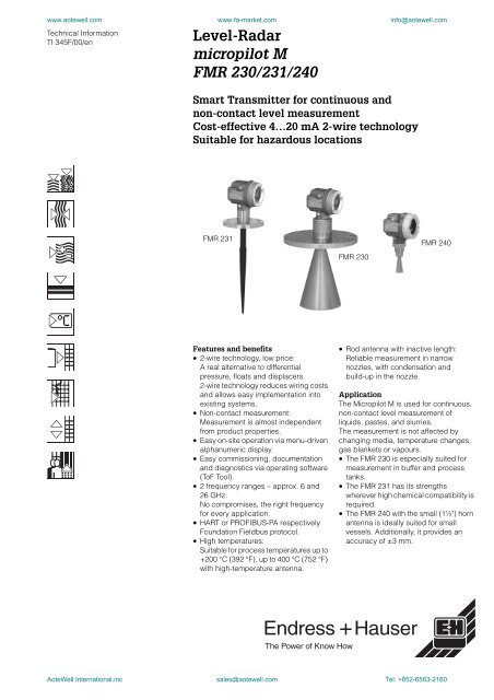
<strong>FMR</strong> <strong>231</strong><br />
<strong>FMR</strong> <strong>230</strong><br />
<strong>FMR</strong> <strong>240</strong><br />
Features and benefits<br />
• 2-wire technology, low price:<br />
A real alternative to differential<br />
pressure, floats and displacers.<br />
2-wire technology reduces wiring costs<br />
and allows easy implementation into<br />
existing systems.<br />
• Non-contact measurement:<br />
Measurement is almost independent<br />
from product properties.<br />
• Easy on-site operation via menu-driven<br />
alphanumeric display.<br />
• Easy commissioning, documentation<br />
and diagnostics via operating software<br />
(ToF Tool).<br />
• 2 frequency ranges – approx. 6 and<br />
26 GHz:<br />
No compromises, the right frequency<br />
for every application.<br />
• HART or PROFIBUS-PA respectively<br />
Foundation Fieldbus protocol.<br />
• High temperatures:<br />
Suitable for process temperatures up to<br />
+200 °C (392 °F), up to 400 °C (752 °F)<br />
with high-temperature antenna.<br />
• Rod antenna with inactive length:<br />
Reliable measurement in narrow<br />
nozzles, with condensation and<br />
build-up in the nozzle.<br />
Application<br />
The Micropilot M is used for continuous,<br />
non-contact level measurement of<br />
liquids, pastes, and slurries.<br />
The measurement is not affected by<br />
changing media, temperature changes,<br />
gas blankets or vapours.<br />
• The <strong>FMR</strong> <strong>230</strong> is especially suited for<br />
measurement in buffer and process<br />
tanks.<br />
• The <strong>FMR</strong> <strong>231</strong> has its strengths<br />
wherever high chemical compatibility is<br />
required.<br />
• The <strong>FMR</strong> <strong>240</strong> with the small (1½") horn<br />
antenna is ideally suited for small<br />
vessels. Additionally, it provides an<br />
accuracy of ±3 mm.<br />
AoteWell International.inc sales@aotewell.com Tel: +852-6563-2160
www.aotewell.com www.fa-market.com info@aotewell.com<br />
Micropilot M<br />
Function and system design<br />
Measuring principle<br />
The Micropilot is a "downward-looking" measuring system, operating based on the time-of-flight<br />
method. It measures the distance from the reference point (process connection) to the product<br />
surface. <strong>Radar</strong> impulses are emitted by an antenna, reflected off the product surface and<br />
received again by the radar system.<br />
L00-<strong>FMR</strong>2xxxx-15-00-00-en-001<br />
Input<br />
The reflected radar impulses are received by the antenna and transmitted into the electronics.<br />
A microprocessor evaluates the signal and identifies the level echo caused by the reflection of the<br />
radar impulse at the product surface. The unambiguous signal identification is accomplished by<br />
the PulseMaster software, based on many years of experience with time-of-flight technology.<br />
The mm-accuracy of the Micropilot S could be achieved with the patented algorithms of the<br />
PhaseMaster software.<br />
The distance D to the product surface is proportional to the time of flight t of the impulse:<br />
D = c · t/2,<br />
with c being the speed of light.<br />
Based on the known empty distance E, the level L is calculated:<br />
L = E – D<br />
Refer to the above figure for the reference point for "E".<br />
The Micropilot is equipped with functions to suppress interference echoes. The user can activate<br />
these functions. They ensure that interference echoes (i.e. from edges and weld seams) are not<br />
interpreted as level echo.<br />
Output<br />
The Micropilot is commissioned by entering an empty distance E (=zero), a full distance F (=span)<br />
and an application parameter. The application parameter automatically adapts the instrument to<br />
the measuring conditions. The data points “E” and “F” correspond with 4mA and 20mA for<br />
instruments with current output. They correspond with 0 % and 100 % for digital outputs and the<br />
display module.<br />
A linearization, based on a table entered either manually or semi-automatically, can be activated<br />
locally or remotely. This function provides a measurement in engineering units and a linear output<br />
signal for spheres, horizontal cylindrical tanks and vessels with conical outlet.<br />
2 Endress+Hauser<br />
AoteWell International.inc sales@aotewell.com Tel: +852-6563-2160
www.aotewell.com www.fa-market.com info@aotewell.com<br />
Micropilot M<br />
Equipment architecture<br />
Stand-alone<br />
The Micropilot M can be used for measurement in a stilling well / bypass as well as in free space.<br />
The instrument provides a 4…20 mA output with HART protocol, or PROFIBUS-PA respectively<br />
Foundation Fieldbus communication.<br />
4…20 mA output with HART protocol.<br />
The complete measuring system consists of:<br />
L00-<strong>FMR</strong>2xxxx-14-00-06-en-001<br />
On-site operation:<br />
• with display and operating module VU 331,<br />
• with a Personal Computer, FXA 193 and the operating software ToF Tool.<br />
The ToF Tool is a graphical operating software for instruments from Endress+Hauser that<br />
operate based on the time-of-flight principle (radar, ultrasonic, guided micro-impulse). It assists<br />
with commissioning, securing data, signal analysis and documentation of the measuring point.<br />
Remote operation:<br />
• with HART handheld DXR 275,<br />
• with a Personal Computer, Commubox FXA 191 and the operating software COMMUWIN II<br />
respectively ToF Tool.<br />
Endress+Hauser 3<br />
AoteWell International.inc sales@aotewell.com Tel: +852-6563-2160
www.aotewell.com www.fa-market.com info@aotewell.com<br />
Micropilot M<br />
System integration via PROFIBUS-PA<br />
A maximum of 32 transmitters (8 if mounted in an explosion hazardous location EEx ia IIC<br />
according to FISCO-model) can be connected to the bus. The segment coupler provides the<br />
operating voltage to the bus. Both on-site as well as remote operation are possible.<br />
The complete measuring system consists of:<br />
L00-<strong>FMR</strong>2xxxx-14-00-06-en-002<br />
System integration via Foundation Fieldbus<br />
A maximum of 32 transmitters (standard, EEx em or EEx d) can be connected to the bus. For<br />
protection class EEx ia IIC: the max. number of transmitters depends on the established rules and<br />
standards for intrinsically safe circuits (EN 60070-14), proof of intrinsically safety. Both on-site as<br />
well as remote operation are possible. The complete measuring system consists of:<br />
L00-<strong>FMR</strong>2xxxx-14-00-06-en-003<br />
4 Endress+Hauser<br />
AoteWell International.inc sales@aotewell.com Tel: +852-6563-2160
www.aotewell.com www.fa-market.com info@aotewell.com<br />
Micropilot M<br />
System integration via Rackbus<br />
Multiple transmitters Micropilot M (or other instruments) can be connected to a higher-level bus<br />
system via a Gateway ZA:<br />
• Every HART transmitter via one interface module FXN 672 each.<br />
• Gateways are available for MODBUS, FIP, PROFIBUS, INTERBUS etc.<br />
• Both on-site as well as remote operation are possible.<br />
L00-<strong>FMR</strong>2xxxx-14-00-06-en-006<br />
Endress+Hauser 5<br />
AoteWell International.inc sales@aotewell.com Tel: +852-6563-2160
www.aotewell.com www.fa-market.com info@aotewell.com<br />
Micropilot M<br />
Input<br />
Measured variable<br />
Measuring range<br />
The measured variable is the distance between a reference point (refer to fig. on page 2) and a<br />
reflective surface (i.e. medium surface).<br />
The level is calculated based on the tank height entered.<br />
The level can be converted into other units (volume, mass) by means of a linearization.<br />
The usable measuring range depends on the size of the antenna, the reflectivity of the medium,<br />
the mounting location and eventual interference reflections.<br />
The following tables describe the groups of media as well as the achievable measuring range as<br />
a function of application and media group. If the dielectric constant of a medium is unknown, it is<br />
recommended to assume media group B to ensure a reliable measurement.<br />
Product class DK (εr) Examples<br />
A 1.4 … 1.9 non-conducting liquids, e.g. liquefied gas 1)<br />
B 1.9 … 4 non-conducting liquids, e.g. benzene, oil, toluene, …<br />
C 4 … 10 e.g. concentrated acids, organic solvents, esters, aniline, alcohol,<br />
acetone, …<br />
D > 10 conducting liquids, e.g. aqueous solutions, dilute acids and alkalis<br />
1) Treat Ammonia NH3 as a medium of group A, i.e. always use a stilling well.<br />
Measuring range depending on vessel type, conditions and product for Micropilot M<br />
<strong>FMR</strong> <strong>230</strong> and <strong>FMR</strong> <strong>231</strong>:<br />
Product class<br />
Storage tank<br />
(scarce<br />
draining/filling)<br />
Buffer tank<br />
(continuous<br />
draining / filling)<br />
Tank with single stage<br />
propeller agitator<br />
Stilling well<br />
Bypass<br />
Measuring range Measuring range Measuring range<br />
Measuring<br />
range<br />
Measuring<br />
range<br />
<strong>FMR</strong> <strong>230</strong>:<br />
DN150<br />
6"<br />
DN200/250<br />
8" / 10"<br />
DN150<br />
6"<br />
DN200/250<br />
8" / 10"<br />
DN150<br />
6"<br />
DN200/250<br />
8" / 10"<br />
DN80…250<br />
3"…10"<br />
DN80…150<br />
3"…6"<br />
<strong>FMR</strong> <strong>231</strong>: Rod antenna — Rod antenna — Rod antenna — — —<br />
A DK(εr)=1.4…1.9 to use the stilling well (20 m / 67 ft) 20 m/67 ft<br />
B DK(εr)=1.9…4 10 m/33 ft 15 m/50 ft 5 m/16 ft 7.5 m/24 ft 4 m/13 ft 6 m/20 ft 20 m/67 ft<br />
2)<br />
2)<br />
C DK(εr)=4…10 15 m/50 ft 20 m/67 ft 7.5 m/24 ft 10 m/33 ft 6 m/20 ft 8 m/27 ft 20 m/67 ft 20 m/67 ft<br />
D DK(εr)>10 20 m/67 ft 20 m/67 ft 10 m/33 ft 12.5 m/42 ft 8 m/27 ft 10 m/33 ft 20 m/67 ft 20 m/67 ft<br />
2) possible, i.e. with stilling well in bypass.<br />
6 Endress+Hauser<br />
AoteWell International.inc sales@aotewell.com Tel: +852-6563-2160
www.aotewell.com www.fa-market.com info@aotewell.com<br />
Micropilot M<br />
Measuring range depending on vessel type, conditions, and product for Micropilot M<br />
<strong>FMR</strong> <strong>240</strong>:<br />
Product class<br />
Storage tank<br />
(scarce draining/filling)<br />
Buffer tank<br />
(continuous draining / filling)<br />
Tank with single stage propeller<br />
agitator<br />
Measuring range Measuring range Measuring range<br />
<strong>FMR</strong> <strong>240</strong>:<br />
1½"<br />
40mm<br />
DN50<br />
2"<br />
DN80<br />
3"<br />
DN100<br />
4"<br />
1½"<br />
40mm<br />
DN50<br />
2"<br />
DN80<br />
3"<br />
DN100<br />
4"<br />
1½"<br />
40mm<br />
DN50<br />
2"<br />
DN80<br />
3"<br />
DN100<br />
4"<br />
A DK(εr)=1.4…1.9 to use the stilling well (20 m / 67 ft)<br />
B<br />
DK(εr)=1.9…4<br />
3 m /<br />
10 ft<br />
5 m /<br />
16 ft<br />
10 m /<br />
33 ft<br />
15 m /<br />
50 ft<br />
2 m /<br />
7ft<br />
2.5 m /<br />
8ft<br />
5 m /<br />
16 ft<br />
7.5 m /<br />
25 ft<br />
1 m /<br />
3ft<br />
1 m /<br />
3ft<br />
2 m /<br />
7ft<br />
3 m /<br />
10 ft<br />
C<br />
DK(εr)=4…10<br />
6 m /<br />
20 ft<br />
10 m /<br />
33 ft<br />
15 m /<br />
50 ft<br />
20 m /<br />
67 ft<br />
3 m /<br />
10 ft<br />
5 m /<br />
16 ft<br />
7.5 m /<br />
25 ft<br />
10 m /<br />
33 ft<br />
1.5 m /<br />
5ft<br />
2 m /<br />
7ft<br />
3 m /<br />
10 ft<br />
5 m /<br />
16 ft<br />
D<br />
DK(εr)>10<br />
9 m /<br />
30 ft<br />
15 m /<br />
50 ft<br />
20 m /<br />
67 ft<br />
20 m /<br />
67 ft<br />
5 m /<br />
16 ft<br />
7.5 m /<br />
25 ft<br />
10 m /<br />
33 ft<br />
12.5 m<br />
/ 42 ft<br />
2 m /<br />
7ft<br />
3 m /<br />
10 ft<br />
5 m /<br />
16 ft<br />
7 m /<br />
23 ft<br />
Product class Stilling well Bypass Wave Guide antenna<br />
Measuring range Measuring range Measuring range<br />
<strong>FMR</strong> <strong>240</strong>:<br />
1½" / 40mm … DN100<br />
1½"…4"<br />
DN50…100<br />
2"…4"<br />
Wave Guide antenna<br />
A DK(εr)=1.4…1.9 20 m/ 67 ft<br />
see pipe antenna<br />
B DK(εr)=1.9…4 20 m/ 67 ft<br />
C DK(εr)=4…10 20 m/ 67 ft 20 m/ 67 ft<br />
depending<br />
on pipe length,<br />
max. 2.8 m (9.2 ft)<br />
D DK(εr)>10 20 m/ 67 ft 20 m/ 67 ft<br />
Endress+Hauser 7<br />
AoteWell International.inc sales@aotewell.com Tel: +852-6563-2160
www.aotewell.com www.fa-market.com info@aotewell.com<br />
Micropilot M<br />
Measuring conditions<br />
Note!<br />
Please use <strong>FMR</strong> <strong>230</strong> respectively <strong>FMR</strong> <strong>231</strong> for boiling surfaces or in case of a tendency for<br />
foaming.<br />
The maximum measuring range of the <strong>FMR</strong><strong>240</strong> may decrease in case of heavy steam<br />
development, depending on density, temperature and composition of the steam (-> please<br />
use <strong>FMR</strong> <strong>230</strong> respectively <strong>FMR</strong> <strong>231</strong>). Please use <strong>FMR</strong> <strong>230</strong> in stilling well for the<br />
measurement of ammonia NH 3 .<br />
• The measuring range begins, where the beam hits the tank bottom. Particularly with dish<br />
bottoms or conical outlets the level cannot be detected below this point.<br />
• In case of media with a low dielectric constant (groups A and B), the tank bottom can be visible<br />
through the medium at low levels. In order to guarantee the required accuracy in these cases,<br />
it is recommended to position the zero-point at a distance (C) above the tank bottom<br />
• In principle it is possible to measure up to the tip of the antenna. However, due to considerations<br />
regarding corrosion and build-up, the end of the measuring range should not be chosen any<br />
closer than 50 mm (2”) to the tip of the antenna.<br />
• The smallest possible measuring range (B) depends on the antenna version.<br />
• The tank diameter should be greater than (D), the tank height at least (H).<br />
• Depending on its consistence, foam can either absorb microwaves or reflect them off the foam<br />
surface. Measurement is possible under certain conditions.<br />
L00-<strong>FMR</strong>2xxxx-17-00-00-en-005<br />
B [m / inch] C [mm / inch] D [m / inch] H [m / ft]<br />
<strong>FMR</strong> <strong>230</strong> / <strong>231</strong> > 0.5 / > 20 150…300 / 6…12 > 1 / > 40 > 1.5 / > 5<br />
<strong>FMR</strong> <strong>240</strong> > 0.2 / > 8 50…150 / 2…6 > 0.2 / > 8 > 0.3 / > 1<br />
8 Endress+Hauser<br />
AoteWell International.inc sales@aotewell.com Tel: +852-6563-2160
www.aotewell.com www.fa-market.com info@aotewell.com<br />
Micropilot M<br />
Output<br />
Output signal<br />
Signal on alarm<br />
• 4…20 mA with HART protocol<br />
• PROFIBUS-PA<br />
• Foundation Fieldbus (FF)<br />
Error information can be accessed via the following interfaces:<br />
• Local display:<br />
– Error symbol (see page 27)<br />
– Plain text display<br />
• Current output<br />
• Digital interface<br />
Auxiliary energy<br />
Electrical connection<br />
Terminal compartment<br />
Two housings are available:<br />
• Housing F 12 with additionally sealed terminal compartment for standard or EEx ia<br />
• Housing T 12 with separate terminal compartment for standard, EEx e or EEx d.<br />
L00-<strong>FMR</strong>2xxxx-04-00-00-en-001<br />
Endress+Hauser 9<br />
AoteWell International.inc sales@aotewell.com Tel: +852-6563-2160
www.aotewell.com www.fa-market.com info@aotewell.com<br />
Micropilot M<br />
Terminal assignment 4…20 mA with HART<br />
The 2-wire cable is connected to the screw<br />
terminals (wire diameter 0.5…2.5mm) in the<br />
terminal compartment.<br />
Use 2-wire twisted pair cable with screen for<br />
the connection.<br />
Protective circuitry against reverse polarity,<br />
RFI, and over-voltage peaks is built into the<br />
device (refer to TI 241F »basics for EMCtests«).<br />
L00-<strong>FMR</strong>2xxxx-04-00-00-en-002<br />
Terminal assignment PROFIBUS-PA<br />
The digital communication signal is transmitted<br />
to the bus via a 2-wire connection. The bus also<br />
provides the auxiliary energy.<br />
Please use 2-wire twisted pair cable with<br />
screen.<br />
Hints regarding architecture and grounding of<br />
the network can be found in BA 198F<br />
»projecting hints PROFIBUS-PA« and the<br />
specification for PROFIBUS-PA.<br />
L00-<strong>FMR</strong>2xxxx-04-00-00-en-003<br />
Terminal assignment Foundation Fieldbus<br />
The digital communication signal is transmitted<br />
to the bus via a 2-wire connection. The bus<br />
also provides the auxiliary energy.<br />
Please use 2-wire twisted pair cable with<br />
screen. Further cable specifications can be<br />
found in the FF specification or the<br />
IEC 61158-2.<br />
Further hints regarding architecture and<br />
grounding of the network can be found at the<br />
Internet address »http://www.fieldbus.org«.<br />
L00-<strong>FMR</strong>2xxxx-04-00-00-en-007<br />
10 Endress+Hauser<br />
AoteWell International.inc sales@aotewell.com Tel: +852-6563-2160
www.aotewell.com www.fa-market.com info@aotewell.com<br />
Micropilot M<br />
Load HART<br />
Cable entry<br />
Supply voltage<br />
Minimum load for HART communication: 250 Ω<br />
Cable gland: M20x1.5 or Pg13.5<br />
Cable entry: G ½ or ½ NPT<br />
PROFIBUS-PA M12 plug<br />
Fieldbus Foundation 7/8" plug<br />
The following values are the voltages across the terminals directly at the instrument:<br />
.<br />
Communication<br />
Current<br />
consumption<br />
minimal<br />
Terminal voltage<br />
maximal<br />
HART<br />
standard<br />
EEx ia<br />
EEx em<br />
EEx d<br />
4 mA 16 V 36 V<br />
20 mA 7.5 V 36 V<br />
4 mA 16 V 30 V<br />
20 mA 7.5 V 30 V<br />
4 mA 16 V 30 V<br />
20 mA 11 V 30 V<br />
Fixed current<br />
(measured value<br />
transferred at HART)<br />
standard 11 mA 10 V 36 V<br />
EEx ia 11 mA 10 V 30 V<br />
Power consumption<br />
Normal operation: min. 60 mW, max. 900 mW<br />
Current consumption .<br />
Communication<br />
HART<br />
PROFIBUS-PA<br />
Foundation Fieldbus (FF)<br />
Current consumption<br />
3.6…22 mA<br />
ca. 13 mA<br />
ca. 15 mA<br />
Endress+Hauser 11<br />
AoteWell International.inc sales@aotewell.com Tel: +852-6563-2160
www.aotewell.com www.fa-market.com info@aotewell.com<br />
Micropilot M<br />
Performance characteristics<br />
Reference operating<br />
conditions<br />
Maximum measured error<br />
• temperature = +20 °C (68 °F) ±5 °C (9 °F)<br />
• pressure = 1013 mbar abs. (14.7 psia) ±20 mbar (0.3 psi)<br />
• relative humidity (air) = 65 % ±20%<br />
• ideal reflector<br />
• no major interference reflections inside the signal beam<br />
Typical statements for reference conditions, include linearity, repeatability, and hysteresis:<br />
.<br />
Type of device to 10 m ex 10 m<br />
<strong>FMR</strong> <strong>230</strong> ±10 mm ±0.1% of measuring range<br />
<strong>FMR</strong> <strong>231</strong> ±10 mm ±0.1% of measuring range<br />
<strong>FMR</strong> <strong>240</strong> ±3 mm ±0.03% of measuring range<br />
Resolution<br />
Reaction time<br />
Influence of ambiente<br />
temperature<br />
Digital / analog in % 4…20 mA<br />
• <strong>FMR</strong> <strong>230</strong>: 1mm / 0.1 % of measuring range<br />
• <strong>FMR</strong> <strong>231</strong>: 1mm / 0.1 % of measuring range<br />
• <strong>FMR</strong> <strong>240</strong>: 1mm / 0.1 % of measuring range<br />
The reaction time depends on the parameter settings (min. 1 s). In case of fast level changes, the<br />
instrument needs the reaction time to indicate the new value.<br />
0.006% / 10 K referring to max. measuring range<br />
12 Endress+Hauser<br />
AoteWell International.inc sales@aotewell.com Tel: +852-6563-2160
www.aotewell.com www.fa-market.com info@aotewell.com<br />
Micropilot M<br />
Operating conditions / Installation<br />
Installation instructions<br />
Orientation<br />
• Recommended distance (1) wall – outer<br />
edge of nozzle: ~1/6 of tank diameter<br />
(<strong>FMR</strong> <strong>230</strong>/<strong>231</strong>: min. 30 cm (12“),<br />
<strong>FMR</strong> <strong>240</strong>: min. 15 cm (6“)).<br />
• Not in the centre (3), interference can cause<br />
signal loss.<br />
• Not above the fill stream (4).<br />
• It is recommended to use a weather<br />
protection cover (2) in order to protect the<br />
transmitter from direct sun or rain. Assembly<br />
and disassembly is simply done by means of<br />
a tension clamp (see »Accessories« on<br />
page 39).<br />
L00-<strong>FMR</strong>2xxxx-17-00-00-xx-001<br />
Tank installations<br />
• Avoid any installations (1), like limit switches,<br />
temperature sensors, etc., inside the signal<br />
beam (refer to beam angle).<br />
• Symmetrical installations (2), i.e. vacuum<br />
rings, heating coils, baffles, etc., can also<br />
interfere with the measurement.<br />
Optimization options<br />
• Antenna size: the bigger the antenna, the<br />
smaller the beam angle, the less interference<br />
echoes.<br />
• Mapping: the measurement can be<br />
optimized by means of electronic<br />
suppression of interference echoes.<br />
• Antenna alignment: refer to "optimum<br />
mounting position"<br />
• Stilling well: a stilling well respectively a<br />
Wave Guide antenna can always be used to<br />
avoid interference.<br />
Please contact Endress+Hauser for further<br />
information.<br />
L00-<strong>FMR</strong>2xxxx-17-00-00-xx-002<br />
Beam angle<br />
The beam angle is defined as the angle α where the energy density of the radar waves reaches<br />
half the value of the maximum energy density (3dB-width). Microwaves are also emitted outside<br />
the signal beam and can be reflected off interfering installations.<br />
Beam angle in dependence of antenna type (diameter).<br />
Antenna size <strong>FMR</strong> <strong>230</strong> <strong>FMR</strong> <strong>231</strong> <strong>FMR</strong> <strong>240</strong><br />
DN150<br />
6"<br />
DN200<br />
8"<br />
DN250<br />
10"<br />
Rod 1½" / 40 mm DN50<br />
2"<br />
DN80<br />
3"<br />
Beam angle α 23° 19° 15° 30° 23° 18° 10° 8°<br />
DN100<br />
4"<br />
Endress+Hauser 13<br />
AoteWell International.inc sales@aotewell.com Tel: +852-6563-2160
www.aotewell.com www.fa-market.com info@aotewell.com<br />
Micropilot M<br />
Installation in tank<br />
(free space) <strong>FMR</strong> <strong>230</strong><br />
Optimum mounting position<br />
L00-<strong>FMR</strong><strong>230</strong>xx-17-00-00-en-001<br />
Standard installation<br />
• Observe installation instructions on page 13.<br />
• Marker is aligned towards tank wall.<br />
• The marker is always exactly in the middle<br />
between two bolt-holes in the flange.<br />
• After mounting, the housing can be turned<br />
350° in order to simplify access to the display<br />
and the terminal compartment.<br />
• The horn antenna must extend below the<br />
nozzle, otherwise use antenna extension<br />
FAR10.<br />
• Align horn antenna vertically.<br />
L00-<strong>FMR</strong><strong>230</strong>xx-17-00-00-en-002<br />
Antenna size 150 mm / 6" 200 mm / 8" 250 mm / 10"<br />
D [mm / inch] 146 / 5.8 191 / 7.5 241 / 9.5<br />
H [mm / inch] < 205 / < 8.1 < 290 / < 11.5 < 380 /
www.aotewell.com www.fa-market.com info@aotewell.com<br />
Micropilot M<br />
Antenna extension FAR 10<br />
• The antenna extension has to be selected<br />
such that the horn extends below the nozzle.<br />
• If the horn diameter is greater than the<br />
nominal width of the nozzle, the antenna<br />
including the extension is mounted from<br />
inside the vessel. The bolts are tightened<br />
from outside, with the instrument lifted up.<br />
The extension has to be selected such that<br />
the instrument can be lifted by at least<br />
100 mm (4”).<br />
L00-<strong>FMR</strong><strong>230</strong>xx-17-00-00-en-003<br />
Special extensions<br />
• If the antenna has to be mounted on a<br />
sloping or vertical vessel wall, an extension<br />
with a 45° respectively 90° bend is available.<br />
• The smallest possible radius R for the bend<br />
is 300 mm (12”).<br />
Please contact Endress+Hauser for further<br />
information.<br />
L00-<strong>FMR</strong><strong>230</strong>xx-17-00-00-yy-004<br />
Measurement from the outside through<br />
plastic walls<br />
• Medium with dielectric constant εr > 10.<br />
• Maximum level 15 cm (6”) below tank ceiling.<br />
• Distance H greater than 100 mm (4”).<br />
• Preferred mounting by means of stand-offs<br />
for adjustment of the ideal distance H.<br />
• If possible, avoid mounting location where<br />
condensation or build-up might occur. In<br />
case of outdoor mounting, the space<br />
between antenna and vessel has to be<br />
protected from the elements.<br />
• Optimum angle β between 15°…20°<br />
• Select vessel construction material with low<br />
dielectric constant and corresponding<br />
thickness. No conductive (black) plastics<br />
(refer to table).<br />
• If possible, use an antenna DN250 / 10".<br />
• Do not mount any potential reflectors (i.e.<br />
pipes) outside the tank in the signal beam.<br />
L00-<strong>FMR</strong><strong>230</strong>xx-17-00-00-en-005<br />
Penetrated material PE PTFE PP Perspex<br />
DK / εr 2.3 2.1 2.3 3.1<br />
Optimum thickness [mm / inch] 17.0 3) / 0.67 3) 18.0 3) / 0.71 3) 17.0 3) / 0.67 3) 14.4 3) / 0.57 3)<br />
3) Other possible values for the thickness are multiples of the values listed (i.e. E: 34 mm (1.34"),<br />
51 mm (2.01"), …)<br />
Endress+Hauser 15<br />
AoteWell International.inc sales@aotewell.com Tel: +852-6563-2160
www.aotewell.com www.fa-market.com info@aotewell.com<br />
Micropilot M<br />
Installation in tank<br />
(free space) <strong>FMR</strong> <strong>231</strong><br />
Optimum mounting position<br />
L00-<strong>FMR</strong><strong>231</strong>xx-17-00-00-en-001<br />
Standard installation<br />
• Observe installation instructions on page 13.<br />
• Marker is aligned towards tank wall.<br />
• The marker is always exactly in the middle between two bolt-holes in the flange.<br />
• After mounting, the housing can be turned 350° in order to simplify access to the display and<br />
the terminal compartment.<br />
• The inactive part of the rod antenna must extend below the nozzle.<br />
• The rod antenna must be aligned vertically.<br />
Material PPS PTFE<br />
Antenna length [mm / inch] 360 / 14 510 / 20 360 / 14 510 / 20<br />
H [mm / inch] < 100 / < 4 < 250 / < 10 < 100 / < 4 < 250 / < 10<br />
L00-<strong>FMR</strong><strong>231</strong>xx-17-00-00-en-002<br />
16 Endress+Hauser<br />
AoteWell International.inc sales@aotewell.com Tel: +852-6563-2160
www.aotewell.com www.fa-market.com info@aotewell.com<br />
Micropilot M<br />
Installation in tank<br />
(free space) <strong>FMR</strong> <strong>240</strong><br />
Optimum mounting position<br />
L00-<strong>FMR</strong><strong>240</strong>xx-17-00-00-en-001<br />
Standard installation<br />
• Observe installation instructions on page 13.<br />
• Marker is aligned towards tank wall.<br />
• The marker is always exactly in the middle<br />
between two bolt-holes in the flange.<br />
• After mounting, the housing can be turned<br />
350° in order to simplify access to the display<br />
and the terminal compartment.<br />
• The horn antenna should extend below the<br />
nozzle. If required, use version with 100 mm<br />
(4”) antenna extension (see page 25).<br />
• The horn antenna must be aligned vertically.<br />
L00-<strong>FMR</strong><strong>240</strong>xx-17-00-00-en-002<br />
Antenna size 1½" / 40 mm DN50 DN80 DN100<br />
D [mm / inch] 40 / 1.5 48 / 1.9 75 / 3 95 / 3.7<br />
H [mm / inch] < 85 / < 3.4 < 115 / < 4.5 < 210 / < 8.3 < 280 / < 11<br />
Endress+Hauser 17<br />
AoteWell International.inc sales@aotewell.com Tel: +852-6563-2160
www.aotewell.com www.fa-market.com info@aotewell.com<br />
Micropilot M<br />
Installation in stilling well<br />
<strong>FMR</strong> <strong>230</strong> / <strong>240</strong><br />
Optimum mounting position<br />
L00-<strong>FMR</strong><strong>230</strong>xx-17-00-00-en-006<br />
Standard installation<br />
• Observe installation instructions on page 13.<br />
• Marker is aligned toward slots.<br />
• The marker is always exactly in the middle between two bolt-holes in the flange.<br />
• After mounting, the housing can be turned 350° in order to simplify access to the display and<br />
the terminal compartment.<br />
• Measurements can be performed through an open ball valve without any problems.<br />
Recommendations for the stilling well<br />
• Metal (no enamel coating, plastic on request).<br />
• Constant diameter.<br />
• Weld seam as smooth as possible and on the same axis as the slots.<br />
• Slots offset 180° (not 90°).<br />
• Slot width respectively diameter of holes max. 1/10 of pipe diameter, de-burred. Length and<br />
number do not have any influence on the measurement.<br />
• Select horn antenna as big as possible. For intermediate sizes (i.e. 180 mm) select next larger<br />
antenna and adapt it mechanically.<br />
• At any transition (i.e. when using a ball valve or mending pipe segments), no gap may be<br />
created exceeding 0.1 mm.<br />
• The stilling well must be smooth on the inside (average roughness Rz ≤ 30). Use extruded or<br />
parallel welded stainless steel pipe. An extension of the pipe is possible with welded flanges or<br />
pipe sleeves. Flange and pipe have to be properly aligned at the inside.<br />
• Do not weld through the pipe wall. The inside of the stilling well must remain smooth. In case of<br />
unintentional welding through the pipe, the weld seam and any unevenness on the inside need<br />
to be carefully removed and smoothened. Otherwise, strong interference echoes will be<br />
generated and material build-up will be promoted.<br />
• Particularly on smaller nominal widths it needs to be observed that flanges are welded to the<br />
pipe such that they allow for a correct orientation (marker aligned toward slots).<br />
18 Endress+Hauser<br />
AoteWell International.inc sales@aotewell.com Tel: +852-6563-2160
www.aotewell.com www.fa-market.com info@aotewell.com<br />
Micropilot M<br />
Examples for the construction of stilling wells<br />
L00-<strong>FMR</strong>2xxxx-17-00-00-en-002<br />
Endress+Hauser 19<br />
AoteWell International.inc sales@aotewell.com Tel: +852-6563-2160
www.aotewell.com www.fa-market.com info@aotewell.com<br />
Micropilot M<br />
Installation in bypass<br />
<strong>FMR</strong> <strong>230</strong> / <strong>240</strong><br />
Optimum mounting position<br />
L00-<strong>FMR</strong><strong>230</strong>xx-17-00-00-en-007<br />
Standard installation<br />
• Observe installation instructions on page 13.<br />
• Marker is aligned perpendicular (90°) to tank connectors.<br />
• The marker is always exactly in the middle between two bolt-holes in the flange.<br />
• After mounting, the housing can be turned 350° in order to simplify access to the display and<br />
the terminal compartment.<br />
• The horn must be aligned vertically.<br />
• Measurements can be performed through an open ball valve without any problems.<br />
Recommendations for the bypass pipe<br />
• Metal (no plastic or enamel coating)<br />
• Constant diameter<br />
• Select horn antenna as big as possible. For<br />
intermediate sizes (i.e. 95 mm) select next<br />
larger antenna and adapt it mechanically.<br />
• At any transition (i.e. when using a ball valve<br />
or mending pipe segments), no gap may be<br />
created exceeding 0.1 mm.<br />
• When using a <strong>FMR</strong> <strong>230</strong>, a limited accuracy<br />
has to be expected in an area 20 cm (8“)<br />
below the upper connection pipe.<br />
L00-<strong>FMR</strong>2xxxx-17-00-00-en-004<br />
20 Endress+Hauser<br />
AoteWell International.inc sales@aotewell.com Tel: +852-6563-2160
www.aotewell.com www.fa-market.com info@aotewell.com<br />
Micropilot M<br />
Installation <strong>FMR</strong> <strong>240</strong><br />
with Wave Guide antenna<br />
Optimum mounting position<br />
L00-<strong>FMR</strong><strong>240</strong>xx-17-00-00-en-003<br />
Standard installation<br />
• Observe installation instructions on page 13.<br />
• Can be mounted in a tank or bypass.<br />
• No alignment is required.<br />
• After mounting, the housing can be turned 350° in order to simplify access to the display and<br />
the terminal compartment.<br />
• Only suitable for media with low viscosity, without the tendency for build-up in the Wave Guide<br />
antenna.<br />
Endress+Hauser 21<br />
AoteWell International.inc sales@aotewell.com Tel: +852-6563-2160
www.aotewell.com www.fa-market.com info@aotewell.com<br />
Micropilot M<br />
Operating conditions / Environment<br />
Ambient temperature<br />
range<br />
Storage temperature<br />
Climate class<br />
Ambient temperature for the transmitter:<br />
• for F12-housing: -40 °C … +80 °C (-40 °F … +176 °F)<br />
• for T12-housing: -40 °C … +80 °C (-40 °F … +176 °F)<br />
A weather protection cover should be used for outdoor operation if the instrument is exposed to<br />
direct sunlight.<br />
-40 °C … +80 °C (-40 °F … +176°F)<br />
DIN EN 60068-2-38 (test Z/AD)<br />
Degree of protection • housing: IP 65, NEMA 4X (open housing: IP20, NEMA 1)<br />
• antenna: IP 68 (NEMA 6P)<br />
Vibration resistance<br />
Cleaning of the antenna<br />
Electromagnetic<br />
compatibility<br />
DIN EN 60068-2-64 / IEC 68-2-64: 20…2000 Hz, 1 (m/s²)²/Hz<br />
The antenna can get contaminated, depending on the application. The emission and reception of<br />
microwaves can thus eventually be hindered. The degree of contamination leading to an error<br />
depends on the medium and the reflectivity, mainly determined by the dielectric constant er. If the<br />
medium tends to cause contamination and deposits, cleaning on a regular basis is<br />
recommended. Care has to be taken not to damage the antenna in the process of a mechanical<br />
or hose-down cleaning (eventually connection for cleaning liquid). The material compatibility has<br />
to be considered if cleaning agents are used!<br />
The maximum permitted temperature at the flange should not be exceeded.<br />
• emissions according to EN 61326; equipment class B<br />
• compatibility according to EN 61326; appendix A (industrial area, 10 V/m) and Namur<br />
recommendation EMC (NE 21).<br />
Operating conditions / Process<br />
Process temperature range See »Ordering information« on page 32 - 38.<br />
Process temperature limits See »Ordering information« on page 32 - 38.<br />
Process pressure limits See »Ordering information« on page 32 - 38.<br />
Dielectric constant • in a stilling well: εr ≥ 1.4<br />
• in free space: εr ≥ 1.9<br />
22 Endress+Hauser<br />
AoteWell International.inc sales@aotewell.com Tel: +852-6563-2160
www.aotewell.com www.fa-market.com info@aotewell.com<br />
Micropilot M<br />
Mechanical construction<br />
Design, dimensions Micropilot M <strong>FMR</strong> <strong>230</strong><br />
L00-<strong>FMR</strong><strong>230</strong>xx-06-00-00-en-001<br />
Endress+Hauser 23<br />
AoteWell International.inc sales@aotewell.com Tel: +852-6563-2160
www.aotewell.com www.fa-market.com info@aotewell.com<br />
Micropilot M<br />
Micropilot M <strong>FMR</strong> <strong>231</strong><br />
L00-<strong>FMR</strong><strong>231</strong>xx-06-00-00-en-001<br />
24 Endress+Hauser<br />
AoteWell International.inc sales@aotewell.com Tel: +852-6563-2160
www.aotewell.com www.fa-market.com info@aotewell.com<br />
Micropilot M<br />
Micropilot M <strong>FMR</strong> <strong>240</strong><br />
L00-<strong>FMR</strong><strong>240</strong>xx-06-00-00-en-001<br />
Endress+Hauser 25<br />
AoteWell International.inc sales@aotewell.com Tel: +852-6563-2160
www.aotewell.com www.fa-market.com info@aotewell.com<br />
Micropilot M<br />
Weight<br />
Micropilot M <strong>FMR</strong> <strong>230</strong> <strong>FMR</strong> <strong>231</strong> <strong>FMR</strong> <strong>240</strong><br />
Weight<br />
Approx. 6 kg<br />
+<br />
weight of flange<br />
Approx. 4 kg<br />
+<br />
weight of flange<br />
Approx. 4 kg<br />
+<br />
weight of flange<br />
Housing<br />
• Types of housings:<br />
– housing F12: with additionally sealed terminal compartment for standard or EEx ia<br />
– housing T12: separate terminal compartment for increased safety respectively explosion<br />
proof<br />
• Material: aluminium, seawater repellent, chromate, powder coated<br />
• Sight window: glass<br />
• Cable entry: M20x1.5; Pg 13.5 (gland included); ½ NPT; G ½ internal thread; PROFIBUS-PA<br />
M12-plug; Fieldbus Foundation 7/8"-plug<br />
Process connection See »Ordering information« on page 32 - 38.<br />
Seal See »Ordering information« on page 32 - 38.<br />
Antenna See »Ordering information« on page 32 - 38.<br />
26 Endress+Hauser<br />
AoteWell International.inc sales@aotewell.com Tel: +852-6563-2160
www.aotewell.com www.fa-market.com info@aotewell.com<br />
Micropilot M<br />
Human interface<br />
Operation concept<br />
Display elements<br />
The display of the process value and the configuration of the Micropilot occur locally by means of<br />
a large 4-line alphanumeric display with plain text information. The guided menu system with<br />
integrated help texts ensures a quick and safe commissioning.<br />
Remote commissioning, including documentation of the measuring point and in-depth analysis<br />
functions, is supported via the ToF Tool, the graphical operating software for E+H time-of-flight<br />
systems.<br />
Liquid crystal display (LCD):<br />
Four lines with 20 characters each. Display contrast adjustable through key combination.<br />
L00-<strong>FMR</strong>2xxxx-07-00-00-en-001<br />
.<br />
Symbol on<br />
the display<br />
continuously on<br />
flashes<br />
Meaning alarm warning<br />
remote<br />
communication<br />
locked<br />
Operating elements<br />
The operating elements are located inside the housing and are accessible for operation by<br />
opening the lid of the housing.<br />
Function of the keys<br />
.<br />
Key(s)<br />
or <br />
or <br />
or <br />
or <br />
and <br />
or<br />
and <br />
Meaning<br />
Navigate upwards in the selection list<br />
Edit numeric value within a function<br />
Navigate downwards in the selection list<br />
Edit numeric value within a function<br />
Navigate to the left within a function group<br />
Navigate to the right within a function group, confirmation.<br />
Contrast settings of the LCD<br />
Endress+Hauser 27<br />
AoteWell International.inc sales@aotewell.com Tel: +852-6563-2160
www.aotewell.com www.fa-market.com info@aotewell.com<br />
Micropilot M<br />
On-site operation Operation with VU 331<br />
The LC-Display VU 331 allows configuration via 3 keys directly at the instrument. All device<br />
functions can be set through a menu system. The menu consists of function groups and functions.<br />
Within a function, application parameters can be read or adjusted. The user is guided through a<br />
complete configuration procedure.<br />
L00-<strong>FMR</strong>xxxxx-07-00-00-de-002<br />
Operation with handheld unit DXR 275<br />
All device functions can be adjusted via a menu operation with the handheld unit DXR 275.<br />
L00-<strong>FMR</strong>2xxxx-07-00-00-yy-002<br />
28 Endress+Hauser<br />
AoteWell International.inc sales@aotewell.com Tel: +852-6563-2160
www.aotewell.com www.fa-market.com info@aotewell.com<br />
Micropilot M<br />
Remote operation<br />
The Micropilot M can be remotely operated via HART, PROFIBUS-PA and Foundation Fieldbus.<br />
On-site adjustments are also possible.<br />
Operation with ToF Tool<br />
The ToF Tool is a graphical operation software for instruments from Endress+Hauser that operate<br />
based on the time-of-flight principle. It is used to support commissioning, securing of data, signal<br />
analysis and documentation of the instruments. It is compatible with the following operating<br />
systems: Win95, Win98, WinNT4.0 and Win2000.<br />
The ToF Tool supports the following functions:<br />
• Online configuration of transmitters<br />
• Signal analysis via envelope curve<br />
• Loading and saving of instrument data (Upload/Download)<br />
• Documentation of measuring point<br />
Menu-guided commissioning:<br />
Signal analysis via envelope curve:<br />
Connection options:<br />
• HART with Commubox FXA 191<br />
• PROFIBUS-PA<br />
• Service-interface with adapter FXA 193<br />
Endress+Hauser 29<br />
AoteWell International.inc sales@aotewell.com Tel: +852-6563-2160
www.aotewell.com www.fa-market.com info@aotewell.com<br />
Micropilot M<br />
Operation with Commuwin II<br />
Commuwin II is an operating software with graphical support for intelligent transmitters with the<br />
communication protocols Rackbus, Rackbus RS 485, INTENSOR, HART or PROFIBUS-PA. It is<br />
compatible with the operating systems Win 3.1/3.11, Win95, Win98 and WinNT4.0.<br />
Commuwin II supports the following functions:<br />
• Online configuration of transmitters<br />
• Loading and saving of instrument data (Upload/Download)<br />
• Orderly visualisation of measured values and limit values<br />
• Display and recording of measured values with a line recorder<br />
• The envelope curve is displayed via ToF Tool<br />
Connections:<br />
• HART with Commubox FXA 191<br />
• PROFIBUS-PA<br />
Operation with NI-FBUS configurator (only Foundation Fieldbus)<br />
The NI-FBUS Configurator is an easy-to-use graphical environment for creating linkages, loops,<br />
and a schedule based on the fieldbus concepts.<br />
You can use the NI-FBUS Configurator to configure a fieldbus network as follows:<br />
• Set block and device tags<br />
• Set device addresses<br />
• Create and edit function block control strategies (function block applications)<br />
• Configure vendor-defined function and transducer blocks<br />
• Create and edit schedules<br />
• Read and write to function block control strategies (function block applications)<br />
• Invoke Device Description (DD) methods<br />
• Display DD menus<br />
• Download a configuration<br />
• Verify a configuration and compare it to a saved configuration<br />
• Monitor a downloaded configuration<br />
• Replace devices<br />
• Log project download changes<br />
• Save and print a configuration<br />
30 Endress+Hauser<br />
AoteWell International.inc sales@aotewell.com Tel: +852-6563-2160
www.aotewell.com www.fa-market.com info@aotewell.com<br />
Micropilot M<br />
Certificates and approvals<br />
CE approval<br />
RF approvals<br />
The measuring system meets the legal requirements of the EC-guidelines. Endress+Hauser<br />
confirms the instrument passing the required tests by attaching the CE-mark.<br />
R&TTE, FCC<br />
Ex approval See »Ordering information« on page 32 - 38.<br />
Overspill protection WHG (in preparation). See »Ordering information« on page 32 - 38.<br />
Sanitary compatibility<br />
External standards and<br />
guidelines<br />
<strong>FMR</strong> <strong>231</strong> with PTFE-antenna made of 3A/FDA-listed TFM 1600. Only in combination with foodgrade<br />
process connection (Tric-lamp, dairy coupling and aseptic coupling).<br />
EN 60529<br />
Protection class of housing (IP-code)<br />
EN 61010<br />
Safety regulations for electrical devices for measurement, control, regulation and laboratory use.<br />
EN 61326<br />
Emissions (equipment class B), compatibility (appendix A – industrial area)<br />
NAMUR<br />
Standards committee for measurement and control in the chemical industry<br />
Endress+Hauser 31<br />
AoteWell International.inc sales@aotewell.com Tel: +852-6563-2160
www.aotewell.com www.fa-market.com info@aotewell.com<br />
Micropilot M<br />
Ordering information<br />
Micropilot M <strong>FMR</strong> <strong>230</strong><br />
Instrument selection<br />
L00-<strong>FMR</strong><strong>230</strong>xx-16-00-00-en-002<br />
10 Certificates<br />
A For non-hazardous areas<br />
1 ATEX II 1/2 G EEx ia IIC T6<br />
2 ATEX II 1/2 G EEx ia IIC T6, note safety instruction (XA) for electrostatic charging!<br />
3 ATEX II 1/2 G EEx em [ia] IIC T6<br />
4 ATEX II 1/2 G EEx d [ia] IIC T6<br />
F For non-hazardous areas + WHG<br />
6 ATEX II 1/2 G EEx ia IIC T6 + WHG<br />
7 ATEX II 1/2 G EEx ia IIC T6 + WHG, note safety instruction (XA) for electrostatic charging!<br />
8 ATEX II 1/2 G EEx em [ia] IIC T6 + WHG<br />
S FM IS - Class I, Division 1, Group A-D<br />
T FM XP - Class I, Division 1, Group A-D<br />
U CSA IS - Class I, Division 1, Group A-D<br />
V CSA XP - Class I, Division 1, Group A-D<br />
K TIIS EEx ia IIC T4<br />
Y Special version<br />
20 Antenna size<br />
2 80 mm / 3"<br />
3 100 mm / 4"<br />
4 150 mm / 6"<br />
5 200 mm / 8"<br />
6 250 mm / 10"<br />
<strong>FMR</strong> <strong>230</strong>- Product designation (part 1)<br />
32 Endress+Hauser<br />
AoteWell International.inc sales@aotewell.com Tel: +852-6563-2160
www.aotewell.com www.fa-market.com info@aotewell.com<br />
Micropilot M<br />
30 Type of antenna, sealing, temperature<br />
Type Sealing Temperature range<br />
V Standard Viton/FKM -20 °C…200 °C / -4 °F…+392 °F<br />
E Standard EPDM -40 °C…150 °C / -40 °F…+302 °F<br />
K Standard Kalrez 0 °C…200 °C / 32 °F…+392 °F<br />
D Standard PTFE -20 °C…200 °C / -4 °F…+392 °F<br />
G High temperature Graphit -60 °C…400 °C / -76 °F…+752 °F<br />
H Enamel antenna PTFE -40 °C…200 °C / -40 °F…+392 °F<br />
Y Special version<br />
40 Process connection, material<br />
Flange Dia/Pressure Standard Material<br />
CM2 DN80 PN16 DIN 2526 Form C SS316Ti<br />
CN2 DN80 PN40 DIN 2526 Form C SS316Ti<br />
CQ2 DN100 PN16 DIN 2526 Form C SS316Ti<br />
CR2 DN100 PN40 DIN 2526 Form C SS316Ti<br />
CW2 DN150 PN16 DIN 2526 Form C SS316Ti<br />
CX2 DN200 PN16 DIN 2526 Form C SS316Ti<br />
C62 DN250 PN16 DIN 2526 Form C SS316Ti<br />
EWT DN150 PN16 DIN 2526 Form E enamelled steel<br />
EXT DN200 PN16 DIN 2526 Form E enamelled steel<br />
CQ5 DN100 PN16 DIN 2526 Form C Hastelloy C4 face<br />
CW5 DN150 PN16 DIN 2526 Form C Hastelloy C4 face<br />
C65 DN250 PN16 DIN 2526 Form C Hastelloy C4 face<br />
AL2 3"/150 lbs ANSI B16.5 SS316Ti<br />
AM2 3"/300 lbs ANSI B16.5 SS316Ti<br />
AP2 4"/150 lbs ANSI B16.5 SS316Ti<br />
AQ2 4"/300 lbs ANSI B16.5 SS316Ti<br />
AV2 6"/150 lbs ANSI B16.5 SS316Ti<br />
A32 8"/150 lbs ANSI B16.5 SS316Ti<br />
A52 10"/150 lbs ANSI B16.5 SS316Ti<br />
AVT 6"/150 lbs ANSI B16.5 enamelled steel<br />
A3T 8"/150 lbs ANSI B16.5 enamelled steel<br />
AV5 6"/150 lbs ANSI B16.5 Hastelloy C4 face<br />
A35 8"/150 lbs ANSI B16.5 Hastelloy C4 face<br />
A55 10"/150 lbs ANSI B16.5 Hastelloy C4 face<br />
KA2 10 K 80 JIS B2210 SS316Ti<br />
KH2 10 K 100 JIS B2210 SS316Ti<br />
KV2 10 K 150 JIS B2210 SS316Ti<br />
KD2 10 K 200 JIS B2210 SS316Ti<br />
K52 10 K 250 JIS B2210 SS316Ti<br />
YY9 Special version<br />
50 Output and menu based operation<br />
A 4…20 mA HART with VU 331 (4-line alphanumeric display)<br />
B 4…20 mA HART<br />
C PROFIBUS-PA with VU 331 (4-line alphanumeric display)<br />
D PROFIBUS-PA<br />
E Foundation Fieldbus with VU 331 (4-line alphanumeric display)<br />
F Foundation Fieldbus<br />
Y Special version<br />
60 Housing<br />
A Aluminium F12-housing, coated, IP65<br />
C Aluminium T12-housing with separate connection compartment, coated, IP65<br />
Y Special version<br />
70 Gland / Entry<br />
1 Pg13.5 cable gland<br />
2 M20x1.5 cable gland<br />
3 G ½ cable entry<br />
4 ½ NPT cable entry<br />
5 PROFIBUS-PA M12 plug<br />
6 Fieldbus Foundation 7/8" plug<br />
9 Special version<br />
80 Additional options<br />
A Additional options not selected<br />
B 3.1.B material, wetted parts SS316Ti, Inspection Certificate EN 10204,<br />
acc. specification 52005759<br />
<strong>FMR</strong> <strong>230</strong>-<br />
Complete product designation<br />
Endress+Hauser 33<br />
AoteWell International.inc sales@aotewell.com Tel: +852-6563-2160
www.aotewell.com www.fa-market.com info@aotewell.com<br />
Micropilot M<br />
Micropilot M <strong>FMR</strong> <strong>231</strong><br />
Instrument selection<br />
L00-<strong>FMR</strong><strong>231</strong>xx-16-00-00-en-002<br />
10 Certificates<br />
A For non-hazardous areas<br />
1 ATEX II 1/2 G EEx ia IIC T6<br />
2 ATEX II 1/2 G EEx ia IIC T6, note safety instruction (XA) for electrostatic charging!<br />
3 ATEX II 1/2 G EEx em [ia] IIC T6<br />
4 ATEX II 1/2 G EEx d [ia] IIC T6<br />
5 ATEX II 1/2 G EEx d [ia] IIC T6, note safety instruction (XA) for electrostatic charging!<br />
F For non-hazardous areas + WHG<br />
6 ATEX II 1/2 G EEx ia IIC T6 + WHG<br />
7 ATEX II 1/2 G EEx ia IIC T6 + WHG, note safety instruction (XA) for electrostatic charging!<br />
8 ATEX II 1/2 G EEx em [ia] IIC T6 + WHG<br />
S FM IS - Class I, Division 1, Group A-D<br />
T FM XP - Class I, Division 1, Group A-D<br />
U CSA IS - Class I, Division 1, Group A-D<br />
V CSA XP - Class I, Division 1, Group A-D<br />
K TIIS EEx ia IIC T4<br />
Y Special version<br />
<strong>FMR</strong> <strong>231</strong>- Product designation (part 1)<br />
34 Endress+Hauser<br />
AoteWell International.inc sales@aotewell.com Tel: +852-6563-2160
www.aotewell.com www.fa-market.com info@aotewell.com<br />
Micropilot M<br />
20 Type of antenna, O-ring, inactive length<br />
Type Length Material O-ring Nozzle length<br />
A Rod antenna 360 mm / 14" PPS, antistatic Viton 100 mm / 4"<br />
B Rod antenna 510 mm / 20" PPS, antistatic Viton 250 mm / 10"<br />
E Rod antenna 360 mm / 14" PTFE, fully insulated 100 mm / 4"<br />
F Rod antenna 510 mm / 20" PTFE, fully insulated 250 mm / 10"<br />
H Rod antenna 360 mm / 14" PTFE, antistatic + fully insulated 100 mm / 4"<br />
J Rod antenna 510 mm / 20" PTFE, antistatic + fully insulated 250 mm / 10"<br />
Y Special version<br />
30 Process connection, material<br />
Threaded connection Material<br />
GGJ 1½" BSPT (R 1½", DIN 2999) SS316L<br />
GGS 1½" BSPT (R 1½", DIN 2999) PVDF<br />
GNJ NPT 1½" SS316L<br />
GNS NPT 1½" PVDF<br />
Flange Dia/Pressure Standard Material<br />
BFJ DN50 PN16 DIN 2526 Form B SS316L<br />
BMJ DN80 PN16 DIN 2526 Form B SS316L<br />
BNJ DN80 PN40 DIN 2526 Form B SS316L<br />
BQJ DN100 PN16 DIN 2526 Form B SS316L<br />
BWJ DN150 PN16 DIN 2526 Form B SS316L<br />
CFJ DN50 PN16 DIN 2526 Form C SS316L<br />
CMJ DN80 PN16 DIN 2526 Form C SS316L<br />
CNJ DN80 PN40 DIN 2526 Form C SS316L<br />
CQJ DN100 PN16 DIN 2526 Form C SS316L<br />
CWJ DN150 PN16 DIN 2526 Form C SS316L<br />
CFK DN50 PN16 DIN 2526 Form C SS316L, PTFE-clad<br />
CMK DN80 PN16 DIN 2526 Form C SS316L, PTFE-clad<br />
CQK DN100 PN16 DIN 2526 Form C SS316L, PTFE-clad<br />
CWK DN150 PN16 DIN 2526 Form C SS316L, PTFE-clad<br />
AEJ 2"/150 lbs ANSI B16.5 SS316L<br />
ALJ 3"/150 lbs ANSI B16.5 SS316L<br />
AMJ 3"/300 lbs ANSI B16.5 SS316L<br />
APJ 4"/150 lbs ANSI B16.5 SS316L<br />
AQJ 4"/300 lbs ANSI B16.5 SS316L<br />
AVJ 6"/150 lbs ANSI B16.5 SS316L<br />
AEK 2"/150 lbs ANSI B16.5 SS316L, PTFE-clad<br />
ALK 3"/150 lbs ANSI B16.5 SS316L, PTFE-clad<br />
APK 4"/150 lbs ANSI B16.5 SS316L, PTFE-clad<br />
AVK 6"/150 lbs ANSI B16.5 SS316L, PTFE-clad<br />
KEJ 10 K 50A JIS B2210 SS316L<br />
KLJ 10 K 80A JIS B2210 SS316L<br />
KPJ 10 K 100A JIS B2210 SS316L<br />
KVJ 10 K 150A JIS B2210 SS316L<br />
KEK 10 K 50A JIS B2210 SS316L, PTFE-clad<br />
KLK 10 K 80A JIS B2210 SS316L, PTFE-clad<br />
KPK 10 K 100A JIS B2210 SS316L, PTFE-clad<br />
KVK 10 K 150A JIS B2210 SS316L, PTFE-clad<br />
Sanitary coupling Standard Material<br />
MFJ DN50 dairy coupling DIN 11851 SS316L<br />
HFJ DN50 aseptic DIN 11864-1 SS316L<br />
TEJ 2" Tri-clamp ISO 2852 SS316L<br />
TLJ 3" Tri-clamp ISO 2852 SS316L<br />
YY9 Special version<br />
40 Output and menu based operation<br />
A 4…20 mA HART with VU 331 (4-line alphanumeric display)<br />
B 4…20 mA HART<br />
C PROFIBUS-PA with VU 331 (4-line alphanumeric display)<br />
D PROFIBUS-PA<br />
E Foundation Fieldbus with VU 331 (4-line alphanumeric display)<br />
F Foundation Fieldbus<br />
Y Special version<br />
50 Housing<br />
A Aluminium F12-housing, coated, IP65<br />
C Aluminium T12-housing with separate connection compartment, coated, IP65<br />
Y Special version<br />
<strong>FMR</strong> <strong>231</strong>- Product designation (part 2)<br />
Endress+Hauser 35<br />
AoteWell International.inc sales@aotewell.com Tel: +852-6563-2160
www.aotewell.com www.fa-market.com info@aotewell.com<br />
Micropilot M<br />
60 Gland / Entry<br />
1 Pg13.5 cable gland<br />
2 M20x1.5 cable gland<br />
3 G ½ cable entry<br />
4 ½ NPT cable entry<br />
5 PROFIBUS-PA M12 plug<br />
6 Fieldbus Foundation 7/8" plug<br />
9 Special version<br />
70 Gastight feed through<br />
A without gastight feed through<br />
C with gastight feed through<br />
80 Additional options<br />
A Additional options not selected<br />
B 3.1.B material, wetted parts SS316Ti, Inspection Certificate EN 10204,<br />
acc. specification 52005759<br />
<strong>FMR</strong> <strong>231</strong>-<br />
Complete product designation<br />
36 Endress+Hauser<br />
AoteWell International.inc sales@aotewell.com Tel: +852-6563-2160
www.aotewell.com www.fa-market.com info@aotewell.com<br />
Micropilot M<br />
Micropilot M <strong>FMR</strong> <strong>240</strong><br />
Instrument selection<br />
L00-<strong>FMR</strong><strong>240</strong>xx-16-00-00-en-002<br />
10 Certificates<br />
A For non-hazardous areas<br />
1 ATEX II 1/2 G EEx ia IIC T6<br />
3 ATEX II 1/2 G EEx em [ia] IIC T6<br />
4 ATEX II 1/2 G EEx d [ia] IIC T6<br />
F For non-hazardous areas + WHG<br />
6 ATEX II 1/2 G EEx ia IIC T6 + WHG<br />
8 ATEX II 1/2 G EEx em [ia] IIC T6 + WHG<br />
S FM IS - Class I, Division 1, Group A-D<br />
T FM XP - Class I, Division 1, Group A-D<br />
U CSA IS - Class I, Division 1, Group A-D<br />
V CSA XP - Class I, Division 1, Group A-D<br />
K TIIS EEx ia IIC T4<br />
Y Special version<br />
20 Antenna size<br />
2 40 mm / 1 ½"<br />
3 50 mm / 2"<br />
4 80 mm / 3"<br />
5 100 mm / 4"<br />
7 mm Wave Guide antenna, inside diameter: 21 mm<br />
8 inch Wave Guide antenna, inside diameter: 21 mm<br />
30 Type of antenna, sealing, temperature<br />
Type Sealing Temperature range<br />
V Standard Viton/FKM -20° C…150° C / -4 °F…+302 °F<br />
E Standard Viton GLT -40° C…150° C / -40 °F…+302 °F<br />
K Standard Kalrez 0° C…150° C / 32 °F…+302 °F<br />
<strong>FMR</strong> <strong>240</strong>- Product designation (part 1)<br />
Endress+Hauser 37<br />
AoteWell International.inc sales@aotewell.com Tel: +852-6563-2160
www.aotewell.com www.fa-market.com info@aotewell.com<br />
Micropilot M<br />
40 Antenna extension<br />
1 without antenna extension<br />
2 100 mm / 4" antenna extension<br />
9 Special length<br />
50 Process connection, material<br />
Threaded connection Material<br />
GNJ NPT 1½" SS316L<br />
GGJ 1½" BSPT (R 1½", DIN 2999) SS316L<br />
Flange Dia/Pressure Standard Material<br />
CFJ DN50 PN16 DIN 2526 Form C SS316L<br />
CGJ DN50 PN40 DIN 2526 Form C SS316L<br />
CMJ DN80 PN16 DIN 2526 Form C SS316L<br />
CNJ DN80 PN40 DIN 2526 Form C SS316L<br />
CQJ DN100 PN16 DIN 2526 Form C SS316L<br />
CRJ DN100 PN40 DIN 2526 Form C SS316L<br />
CWJ DN150 PN16 DIN 2526 Form C SS316L<br />
AEJ 2"/150 lbs ANSI B16.5 SS316L<br />
AFJ 2"/300 lbs ANSI B16.5 SS316L<br />
ALJ 3"/150 lbs ANSI B16.5 SS316L<br />
AMJ 3"/300 lbs ANSI B16.5 SS316L<br />
APJ 4"/150 lbs ANSI B16.5 SS316L<br />
AQJ 4"/300 lbs ANSI B16.5 SS316L<br />
AWJ 6"/150 lbs ANSI B16.5 SS316L<br />
KEJ 10 K 50A JIS B2210 SS316L<br />
KLJ 10 K 80A JIS B2210 SS316L<br />
KPJ 10 K 100A JIS B2210 SS316L<br />
KWJ 10 K 150A JIS B2210 SS316L<br />
YY9 Special version<br />
60 Output and menu based operation<br />
A 4…20 mA HART with VU 331 (4-line alphanumeric display)<br />
B 4…20 mA HART<br />
C PROFIBUS-PA with VU 331 (4-line alphanumeric display)<br />
D PROFIBUS-PA<br />
E Foundation Fieldbus with VU 331 (4-line alphanumeric display)<br />
F Foundation Fieldbus<br />
Y Special version<br />
70 Housing<br />
A Aluminium F12-housing, coated, IP65<br />
C Aluminium T12-housing with separate connection compartment, coated, IP65<br />
Y Special version<br />
80 Gland / Entry<br />
1 Pg13.5 cable gland<br />
2 M20x1.5 cable gland<br />
3 G ½ cable entry<br />
4 ½ NPT cable entry<br />
5 PROFIBUS-PA M12 plug<br />
6 Fieldbus Foundation 7/8" plug<br />
9 Special version<br />
90 Additional options<br />
A Additional options not selected<br />
B 3.1.B material, wetted parts SS316Ti, Inspection Certificate EN 10204,<br />
acc. specification 52005759<br />
<strong>FMR</strong> <strong>240</strong>-<br />
Complete product designation<br />
38 Endress+Hauser<br />
AoteWell International.inc sales@aotewell.com Tel: +852-6563-2160
www.aotewell.com www.fa-market.com info@aotewell.com<br />
Micropilot M<br />
Accessories<br />
Protective cover A protective cover made of stainless steel is available for outdoor mounting (order code: 543199-<br />
0001). The shipment includes the protective cover and tension clamp.<br />
Antenna extension<br />
FAR 10 (for <strong>FMR</strong> <strong>230</strong>)<br />
Dimensions<br />
L00-<strong>FMR</strong>xxxxx-06-00-00-en-002<br />
L00-<strong>FMR</strong>2xxxx-06-00-00-en-001<br />
Ordering information<br />
10 Material<br />
2 1.4571<br />
4 2.4600/Hastelloy B3<br />
5 2.4610/Hastelloy C4<br />
9 Special material<br />
80 Overall length L1<br />
A 100 mm / 4"<br />
B 200 mm / 8"<br />
C 300 mm / 12"<br />
D 400 mm / 16"<br />
Y Special length<br />
FAR 10-<br />
Complete product designation<br />
Commubox FXA 191<br />
Service adapter FXA 193<br />
For intrinsically safe communication with ToF Tool or Commuwin II via the RS 232C-interface.<br />
For communication with ToF Tool via the display connector.<br />
Endress+Hauser 39<br />
AoteWell International.inc sales@aotewell.com Tel: +852-6563-2160
www.aotewell.com www.fa-market.com info@aotewell.com<br />
Micropilot M<br />
Documentation<br />
System Information<br />
Operating Instructions<br />
SI 019F/00/en<br />
System Information for Micropilot<br />
BA 218F/00/en<br />
Operating Instructions for Micropilot M <strong>FMR</strong> <strong>230</strong> (HART)<br />
BA 219F/00/en<br />
Operating Instructions for Micropilot M <strong>FMR</strong> <strong>231</strong> (HART)<br />
BA 220F/00/en<br />
Operating Instructions for Micropilot M <strong>FMR</strong> <strong>240</strong> (HART)<br />
BA 225F/00/en<br />
Operating Instructions for Micropilot M <strong>FMR</strong> <strong>230</strong> (PROFIBUS-PA)<br />
BA 226F/00/en<br />
Operating Instructions for Micropilot M <strong>FMR</strong> <strong>231</strong> (PROFIBUS-PA)<br />
BA 227F/00/en<br />
Operating Instructions for Micropilot M <strong>FMR</strong> <strong>240</strong> (PROFIBUS-PA)<br />
BA 228F/00/en<br />
Operating Instructions for Micropilot M <strong>FMR</strong> <strong>230</strong> (Foundation Fieldbus)<br />
BA 229F/00/en<br />
Operating Instructions for Micropilot M <strong>FMR</strong> <strong>231</strong> (Foundation Fieldbus)<br />
BA <strong>230</strong>F/00/en<br />
Operating Instructions for Micropilot M <strong>FMR</strong> <strong>240</strong> (Foundation Fieldbus)<br />
BA 221F/00/en<br />
Description of instrument functions (HART, PROFIBUS-PA, Foundation Fieldbus)<br />
KA 159F/00/a2<br />
Short manual (quick reference) in housing (HART)<br />
KA 160F/00/a2<br />
Short manual (quick reference) in housing (PROFIBUS-PA)<br />
KA 166F/00/a2<br />
Short manual (quick reference) in housing (Foundation Fieldbus)<br />
KA 169F/00/a6<br />
Installation ToF Tool (README- and PDF-file on the included CD-ROM)<br />
BA 224F/00/en<br />
Operation ToF Tool (online-help and PDF-file on the included CD-ROM)<br />
40 Endress+Hauser<br />
AoteWell International.inc sales@aotewell.com Tel: +852-6563-2160
www.aotewell.com www.fa-market.com info@aotewell.com<br />
Micropilot M<br />
Certificates<br />
XA 099F-A<br />
Installation Micropilot M <strong>FMR</strong> 2xx (F12 / EEx ia IIC T6)<br />
PTB 00 ATEX 2118, Equipment marking: (II 1/2 G)<br />
XA 100F-A<br />
Installation Micropilot M <strong>FMR</strong> 2xx (T12 / EEx em [ia] IIC T6)<br />
PTB 00 ATEX 2118, Equipment marking: (II 1/2 G)<br />
XA 101F-A<br />
Installation Micropilot M <strong>FMR</strong> 2xx (T12 / EEx d [ia] IIC T6)<br />
PTB 00 ATEX 2118, Equipment marking: (II 1/2 G)<br />
XA 102F-A<br />
Installation Micropilot M <strong>FMR</strong> 2xx PROFIBUS-PA (F12 / EEx ia IIC T6)<br />
PTB 00 ATEX 2118, Equipment marking: (II 1/2 G)<br />
XA 103F-A<br />
Installation Micropilot M <strong>FMR</strong> 2xx (F12 / EEx ia IIC T6)<br />
PTB 00 ATEX 2117 X, Equipment marking: (II 1/2 G)<br />
XA 104F-A<br />
Installation Micropilot M <strong>FMR</strong> 2xx (T12 / EEx em [ia] IIC T6)<br />
PTB 00 ATEX 2117 X, Equipment marking: (II 1/2 G)<br />
XA 105F-A<br />
Installation Micropilot M <strong>FMR</strong> 2xx (T12 / EEx d [ia] IIC T6)<br />
PTB 00 ATEX 2117 X, Equipment marking: (II 1/2 G)<br />
XA 106F-A<br />
Installation Micropilot M <strong>FMR</strong> 2xx PROFIBUS-PA (F12 / EEx ia IIC T6)<br />
PTB 00 ATEX 2117 X, Equipment marking: (II 1/2 G)<br />
XA 123F-A<br />
Installation Micropilot M <strong>FMR</strong> 2xx Foundation Fieldbus (F12 / EEx ia IIC T6)<br />
PTB 00 ATEX 2117 X, Equipment marking: (II 1/2 G)<br />
XA 124F-A<br />
Installation Micropilot M <strong>FMR</strong> 2xx Foundation Fieldbus (T12 / EEx em [ia] IIC T6)<br />
PTB 00 ATEX 2117 X, Equipment marking: (II 1/2 G)<br />
XA 125F-A<br />
Installation Micropilot M <strong>FMR</strong> 2xx Foundation Fieldbus (T12 / EEx d [ia] IIC T6)<br />
PTB 00 ATEX 2117 X, Equipment marking: (II 1/2 G)<br />
XA 126F-A<br />
Installation Micropilot M <strong>FMR</strong> 2xx Foundation Fieldbus (F12 / EEx ia IIC T6)<br />
PTB 00 ATEX 2118, Equipment marking: (II 1/2 G)<br />
XA 127F-A<br />
Installation Micropilot M <strong>FMR</strong> 2xx Foundation Fieldbus (T12 / EEx em [ia] IIC T6)<br />
PTB 00 ATEX 2118, Equipment marking: (II 1/2 G)<br />
XA 128F-A<br />
Installation Micropilot M <strong>FMR</strong> 2xx Foundation Fieldbus (T12 / EEx d [ia] IIC T6)<br />
PTB 00 ATEX 2118, Equipment marking: (II 1/2 G)<br />
Endress+Hauser 41<br />
AoteWell International.inc sales@aotewell.com Tel: +852-6563-2160
www.aotewell.com www.fa-market.com info@aotewell.com<br />
Micropilot M<br />
ZD 055F/00<br />
Control drawing Micropilot M <strong>FMR</strong> 2xx HART<br />
FM, IS (F12 / Ex ia IIC)<br />
ZD 056F/00<br />
Control drawing Micropilot M <strong>FMR</strong> 2xx PROFIBUS-PA<br />
FM, IS (F12 / Ex ia IIC)<br />
ZD 057F/00<br />
Control drawing Micropilot M <strong>FMR</strong> 2xx Foundation Fieldbus<br />
FM, IS (F12 / Ex ia IIC)<br />
ZD 058F/00<br />
Control drawing Micropilot M <strong>FMR</strong> 2xx HART<br />
FM, XP-IS (T12 / Ex d [ia] IIC)<br />
ZD 059F/00<br />
Control drawing Micropilot M <strong>FMR</strong> 2xx HART<br />
CSA, IS (F12 / Ex ia IIC)<br />
ZD 060F/00<br />
Control drawing Micropilot M <strong>FMR</strong> 2xx PROFIBUS-PA<br />
CSA, IS (F12 / Ex ia IIC)<br />
ZD 061F/00<br />
Control drawing Micropilot M <strong>FMR</strong> 2xx Foundation Fieldbus<br />
CSA, IS (F12 / Ex ia IIC)<br />
ZD 062F/00<br />
Control drawing Micropilot M <strong>FMR</strong> 2xx HART<br />
CSA, XP-IS (T12 / Ex d [ia] IIC)<br />
42 Endress+Hauser<br />
AoteWell International.inc sales@aotewell.com Tel: +852-6563-2160
www.aotewell.com www.fa-market.com info@aotewell.com<br />
Micropilot M<br />
Endress+Hauser 43<br />
AoteWell International.inc sales@aotewell.com Tel: +852-6563-2160
www.aotewell.com www.fa-market.com info@aotewell.com<br />
Micropilot M<br />
This product may be protected by at least one of the following listed patents.<br />
Further patents are pending.<br />
• US 5,387,918 EP 0 535 196<br />
• US 5,689,265 EP 0 626 063<br />
• US 5,659,321<br />
• US 5,614,911 EP 0 670 048<br />
• US 5,594,449 EP 0 676 037<br />
• US 6,047,598<br />
• US 5,880,698<br />
• US 5,926,152<br />
• US 5,969,666<br />
• US 5,948,979<br />
• US 6,054,946<br />
• US 6,087,978<br />
• US 6,014,100<br />
Deutschland Österreich Schweiz<br />
Endress+Hauser Messtechnik GmbH+Co.<br />
Techn. Büro Teltow<br />
Potsdamer Straße 12a<br />
14513 Teltow<br />
Tel. (03328) 4358-0<br />
Fax (03328) 4358-341<br />
E-Mail: Vertrieb Teltow<br />
@de.endress.com<br />
Techn. Büro Frankfurt<br />
Eschborner Landstr. 42<br />
60489 Frankfurt<br />
Tel. (069) 97885-0<br />
Fax (069) 7894582<br />
E-Mail:Vertrieb Frankfurt<br />
@de.endress.com<br />
Techn. Büro Hamburg<br />
Am Stadtrand 52<br />
22047 Hamburg<br />
Tel. (040) 694497-0<br />
Fax (040) 694497-150<br />
E-Mail: Vertrieb Hamburg<br />
@de.endress.com<br />
Techn. Büro Stuttgart<br />
Mittlerer Pfad 4<br />
70499 Stuttgart<br />
Tel. (0711) 1386-0<br />
Fax (0711) 1386-222<br />
E-Mail: Vertrieb Stuttgart<br />
@de.endress.com<br />
Techn. Büro Hannover<br />
Misburger Straße 81 B<br />
30625 Hannover<br />
Tel. (0511) 28372-0<br />
Fax (0511) 28372-333<br />
E-Mail: Vertrieb Hannover<br />
@de.endress.com<br />
Techn. Büro München<br />
Stettiner Straße 5<br />
82110 Germering<br />
Tel. (089) 84009-0<br />
Fax (089) 84009-133<br />
E-Mail: Vertrieb Muenchen<br />
@de.endress.com<br />
Techn. Büro Ratingen<br />
Eisenhüttenstraße 12<br />
40882 Ratingen<br />
Tel. (02102) 859-0<br />
Fax (02102) 859-130<br />
E-Mail: Vertrieb Ratingen<br />
@de.endress.com<br />
Endress+Hauser<br />
Ges.m.b.H.<br />
Postfach 173<br />
1235 Wien<br />
Tel. (01) 88056-0<br />
Fax (01) 88056-35<br />
E-Mail:<br />
info@at.endress.com<br />
Internet:<br />
www.at.endress.com<br />
Endress+Hauser AG<br />
Sternenhofstraße 21<br />
4153 Reinach/BL 1<br />
Tel. (061) 7157575<br />
Fax (061) 7111650<br />
E-Mail:<br />
info@ch.endress.com<br />
Internet:<br />
www.ch.endress.com<br />
Vertriebszentrale Endress+Hauser Messtechnik GmbH+Co. • Postfach 2222<br />
Deutschland: 79574 Weil am Rhein • Tel. (07621) 975-01 • Fax (07621) 975-555<br />
E-Mail: info@de.endress.com • Internet: www.de.endress.com<br />
TI 345F/00/en/10.00<br />
FM+SGML5.5<br />
AoteWell International.inc sales@aotewell.com Tel: +852-6563-2160