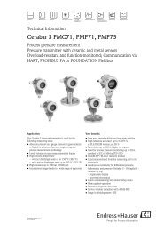
Rosemount 3051 Pressure Transmitter
Rosemount 3051 Pressure Transmitter - from AoteWell
Rosemount 3051 Pressure Transmitter - from AoteWell
- No tags were found...
You also want an ePaper? Increase the reach of your titles
YUMPU automatically turns print PDFs into web optimized ePapers that Google loves.
www.rosemount.aotewell.com sales@aotewell.com AoteWell Sales team<br />
<strong>Rosemount</strong> <strong>3051</strong><br />
Product Data Sheet<br />
00813-0100-4001, Rev HA<br />
March 2008<br />
Zero and Span Adjustment Requirements<br />
(HART and Low Power)<br />
Zero and span values can be set anywhere within the range limits<br />
stated in Table 1 and Table 2.<br />
Span must be greater than or equal to the minimum span stated in<br />
Table 1 and Table 2.<br />
Service<br />
Liquid, gas, and vapor applications<br />
4–20 mA (Output Code A)<br />
Output<br />
Two-wire 4–20 mA, user-selectable for linear or square root<br />
output. Digital process variable superimposed on 4–20 mA<br />
signal, available to any host that conforms to the HART protocol.<br />
Power Supply<br />
External power supply required. Standard transmitter (4–20 mA)<br />
operates on 10.5 to 55 V dc with no load.<br />
Load Limitations<br />
Maximum loop resistance is determined by the voltage level of<br />
the external power supply, as described by:<br />
Max. Loop Resistance = 43.5 (Power Supply Voltage – 10.5)<br />
Load (Ohms)<br />
Operating<br />
Region<br />
Voltage (V dc)<br />
Communication requires a minimum<br />
loop resistance of 250 ohms.<br />
(1) For CSA approval, power supply must not exceed 42.4 V.<br />
FOUNDATION fieldbus (output code F) and<br />
Profibus (output code W)<br />
Power Supply<br />
External power supply required; transmitters operate on 9.0 to<br />
32.0 V dc transmitter terminal voltage.<br />
Current Draw<br />
17.5 mA for all configurations (including LCD display option)<br />
FOUNDATION fieldbus Function Block Execution Times<br />
Block<br />
Execution Time<br />
Resource -<br />
Transducer -<br />
LCD Block -<br />
Analog Input 1, 2<br />
30 milliseconds<br />
PID<br />
45 milliseconds<br />
Input Selector<br />
30 milliseconds<br />
Arithmetic<br />
35 milliseconds<br />
Signal Characterizer<br />
40 milliseconds<br />
Integrator<br />
35 milliseconds<br />
FOUNDATION fieldbus Parameters<br />
Schedule Entries<br />
Links<br />
Virtual Communications Relationships (VCR)<br />
7 (max.)<br />
20 (max.)<br />
12 (max.)<br />
Standard Function Blocks<br />
Resource Block<br />
Contains hardware, electronics, and diagnostic information.<br />
Transducer Block<br />
Contains actual sensor measurement data including the sensor<br />
diagnostics and the ability to trim the pressure sensor or recall<br />
factory defaults.<br />
LCD Block<br />
Configures the local display.<br />
2 Analog Input Blocks<br />
Processes the measurements for input into other function<br />
blocks. The output value is in engineering units or custom and<br />
contains a status indicating measurement quality.<br />
PID Block<br />
Contains all logic to perform PID control in the field including<br />
cascade and feedforward.<br />
Backup Link Active Scheduler (LAS)<br />
The transmitter can function as a Link Active Scheduler if the<br />
current link master device fails or is removed from the segment.<br />
Advanced Control Function Block Suite (Option Code A01)<br />
Input Selector Block<br />
Selects between inputs and generates an output using specific<br />
selection strategies such as minimum, maximum, midpoint,<br />
average or first “good.”<br />
Arithmetic Block<br />
Provides pre-defined application-based equations including flow<br />
with partial density compensation, electronic remote seals,<br />
hydrostatic tank gauging, ratio control and others.<br />
Signal Characterizer Block<br />
Characterizes or approximates any function that defines an<br />
input/output relationship by configuring up to twenty X, Y<br />
coordinates. The block interpolates an output value for a given<br />
input value using the curve defined by the configured<br />
coordinates.<br />
Integrator Block<br />
Compares the integrated or accumulated value from one or two<br />
variables to pre-trip and trip limits and generates discrete output<br />
signals when the limits are reached. This block is useful for<br />
calculating total flow, total mass, or volume over time.<br />
FOUNDATION fieldbus Diagnostics Suite (Option Code D01)<br />
The <strong>3051</strong>C FOUNDATION fieldbus Diagnostics provide Abnormal<br />
Situation Prevention (ASP) indictation. The integral statistical<br />
process monitoring (SPM) technology calculates the mean and<br />
standard deviation of the process variable 22 times per second.<br />
The <strong>3051</strong>C ASP algorithm uses these values and highly flexible<br />
configuration options for customization to many user-defined or<br />
application specific abnormal situations. The detection of<br />
plugged impulse lines is the first available predefined<br />
application.<br />
8<br />
info@aotewell.com


