Rosemount 3051 Pressure Transmitter
Rosemount 3051 Pressure Transmitter - from AoteWell
Rosemount 3051 Pressure Transmitter - from AoteWell
- No tags were found...

You also want an ePaper? Increase the reach of your titles
YUMPU automatically turns print PDFs into web optimized ePapers that Google loves.
www.rosemount.aotewell.com sales@aotewell.com AoteWell Sales team<br />
Product Data Sheet<br />
00813-0100-4001, Rev HA<br />
March 2008 <strong>Rosemount</strong> <strong>3051</strong><br />
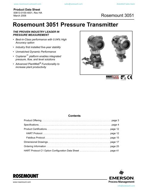
<strong>Rosemount</strong> <strong>3051</strong> <strong>Pressure</strong> <strong>Transmitter</strong><br />
THE PROVEN INDUSTRY LEADER IN<br />
PRESSURE MEASUREMENT<br />
• Best-in-Class performance with 0.04% High<br />
Accuracy option<br />
• Industry first installed five-year stability<br />
• Unmatched Dynamic Performance<br />
• Coplanar platform enables integrated<br />
pressure, flow, and level solutions<br />
• Advanced PlantWeb ® Functionality to<br />
increase plant productivity<br />
Contents<br />
Product Offering. . . . . . . . . . . . . . . . . . . . . . . . . . . . . . . . . . . . . . . . . . . . . . . . . . . . .page 3<br />
Specifications. . . . . . . . . . . . . . . . . . . . . . . . . . . . . . . . . . . . . . . . . . . . . . . . . . . . . . .page 4<br />
Product Certifications. . . . . . . . . . . . . . . . . . . . . . . . . . . . . . . . . . . . . . . . . . . . . . . .page 12<br />
HART Protocol . . . . . . . . . . . . . . . . . . . . . . . . . . . . . . . . . . . . . . . . . . . . . . . . . . .page 12<br />
Fieldbus Protocol . . . . . . . . . . . . . . . . . . . . . . . . . . . . . . . . . . . . . . . . . . . . . . . . .page 15<br />
Dimensional Drawings. . . . . . . . . . . . . . . . . . . . . . . . . . . . . . . . . . . . . . . . . . . . . . .page 17<br />
Ordering Information . . . . . . . . . . . . . . . . . . . . . . . . . . . . . . . . . . . . . . . . . . . . . . . .page 25<br />
HART Protocol C1 Option Configuration Data Sheet . . . . . . . . . . . . . . . . . . . . . . .page 41<br />
www.rosemount.com<br />
info@aotewell.com
www.rosemount.aotewell.com sales@aotewell.com AoteWell Sales team<br />
<strong>Rosemount</strong> <strong>3051</strong><br />
Product Data Sheet<br />
00813-0100-4001, Rev HA<br />
March 2008<br />
Setting the Standard for <strong>Pressure</strong> Measurement<br />
Industry’s best total performance, a flexible Coplanar platform, and installed five-year stability, has made the<br />
<strong>Rosemount</strong> <strong>3051</strong> the standard in pressure measurement.<br />
Industry’s best-in-class total performance<br />
of ±0.15%<br />
Total performance is the true measure of “real-world”<br />
transmitter performance. Using superior sensor<br />
technology and engineered for optimal performance,<br />
the <strong>3051</strong> delivers unprecedented ±0.04% reference<br />
accuracy, resulting in total operating performance of<br />
±0.15%. Superior total performance equates to<br />
reduced variability and improved plant safety.<br />
Installed five-year stability of ±0.125%<br />
<strong>Transmitter</strong> stability is a critical measure of<br />
transmitter performance over time. Through<br />
aggressive simulation testing beyond standard IEC<br />
770 testing, the <strong>3051</strong> has proven its ability to<br />
maintain performance over a five year period under<br />
the most demanding process conditions. Superior<br />
transmitter stability reduces calibration frequency to<br />
save operation and maintenance costs.<br />
Coplanar platform enables complete point<br />
solutions<br />
The versatile Coplanar platform design enables the<br />
best process connection for pressure, flow and level<br />
applications. Right out of the box, the solution arrives<br />
factory calibrated, pressure-tested, and ready to<br />
install. Only the <strong>3051</strong> has a flexible design to reduce<br />
engineering and inventory costs.<br />
Advanced PlantWeb Functionality<br />
The <strong>3051</strong> powers the PlantWeb<br />
architecture by delivering the best<br />
sensor and transmitter, best installation<br />
practices, and best in class field<br />
intelligence. One component is the<br />
enhanced diagnostic capabilities in<br />
FOUNDATION fieldbus that provide an increase in<br />
process visibility, enabling proactive maintenance,<br />
improving process availability and plant productivity.<br />
Unmatched dynamic performance<br />
In dynamic applications, speed of measurement is as<br />
important as repeatability. The <strong>3051</strong> responds up to<br />
eight times faster than the typical pressure<br />
transmitter to detect and control variations quickly<br />
and efficiently. Superior dynamic response yields<br />
more accurate measurements to reduce variability<br />
and increase profitability.<br />
<strong>Rosemount</strong> <strong>Pressure</strong> Solutions<br />
<strong>Rosemount</strong> <strong>3051</strong>S Series of Instrumentation<br />
Scalable pressure, flow and level measurement solutions improve<br />
installation and maintenance practices.<br />
<strong>Rosemount</strong> 3095MV Mass Flow <strong>Transmitter</strong><br />
Accurately measures differential pressure, static pressure and<br />
process temperature to dynamically calculate fully compensated<br />
mass flow.<br />
<strong>Rosemount</strong> 305 and 306 Integral Manifolds<br />
Factory-assembled, calibrated and seal-tested manifolds reduce<br />
on-site installation costs.<br />
<strong>Rosemount</strong> 1199 Diaphragm Seals<br />
Provides reliable, remote measurements of process pressure and<br />
protects the transmitter from hot, corrosive, or viscous fluids.<br />
Orifice Plate Primary Element Systems: <strong>Rosemount</strong><br />
1495 and 1595 Orifice Plates, 1496 Flange Unions and<br />
1497 Meter Sections<br />
A comprehensive offering of orifice plates, flange unions and<br />
meter sections that is easy to specify and order. The 1595<br />
Conditioning Orifice provides superior performance in tight fit<br />
applications.<br />
Annubar ® Flowmeter Series: <strong>Rosemount</strong> <strong>3051</strong>SFA,<br />
3095MFA, and 485<br />
The state-of-the-art, fifth generation <strong>Rosemount</strong> 485 Annubar<br />
combined with the <strong>3051</strong>S or 3095MV MultiVariable transmitter<br />
creates an accurate, repeatable and dependable insertion-type<br />
flowmeter.<br />
Compact Orifice Flowmeter Series: <strong>Rosemount</strong><br />
<strong>3051</strong>SFC, 3095MFC, and 405<br />
Compact Orifice Flowmeters can be installed between existing<br />
flanges, up to a Class 600 (PN100) rating. In tight fit applications,<br />
a conditioning orifice plate version is available, requiring only two<br />
diameters of straight run upstream.<br />
ProPlate ® Flowmeter Series: <strong>Rosemount</strong> ProPlate,<br />
Mass ProPlate, and 1195<br />
These integral orifice flowmeters eliminate the inaccuracies that<br />
become more pronounced in small orifice line installations. The<br />
completely assembled, ready to install flowmeters reduce cost and<br />
simplify installation.<br />
2<br />
info@aotewell.com
www.rosemount.aotewell.com sales@aotewell.com AoteWell Sales team<br />
Product Data Sheet<br />
00813-0100-4001, Rev HA<br />
March 2008<br />
<strong>Rosemount</strong> <strong>3051</strong><br />
Product Offering<br />
<strong>Rosemount</strong> <strong>3051</strong>C Differential, Gage, and Absolute<br />
See ordering information on page 25.<br />
• Performance up to 0.04% accuracy<br />
• Installed five-year stability of 0.125%<br />
• Coplanar platform enables integrated manifold,<br />
primary element and diaphragm seal solutions<br />
• Calibrated spans/ranges from 0.1 inH 2 O to 4000 psi<br />
(0,25 mbar to 276 bar)<br />
• 316L SST, Hastelloy ® C276, Monel ® , Tantalum, Gold-plated<br />
Monel, or Gold-plated 316L SST process isolators<br />
<strong>Rosemount</strong> <strong>3051</strong>T Gage and Absolute<br />
See ordering information on page 29.<br />
• Performance up to 0.04% accuracy<br />
• Installed five-year stability of 0.125%<br />
• Calibrated spans from 0.3 to 10000 psi<br />
(10,3 mbar to 689 bar)<br />
• Multiple process connections available<br />
• 316L SST and Hastelloy C276 process isolators<br />
<strong>Rosemount</strong> <strong>3051</strong>L Liquid Level<br />
See ordering information on page 31.<br />
• Performance up to 0.075% accuracy<br />
• Welded fill fluid system provides<br />
best-in-class system reliability<br />
• Flush and extended diaphragms<br />
• Multiple fill fluids and wetted materials<br />
available<br />
3<br />
info@aotewell.com
www.rosemount.aotewell.com sales@aotewell.com AoteWell Sales team<br />
<strong>Rosemount</strong> <strong>3051</strong><br />
Product Data Sheet<br />
00813-0100-4001, Rev HA<br />
March 2008<br />
PERFORMANCE SPECIFICATIONS<br />
Reference Accuracy (1)<br />
Specifications<br />
Total Performance is based on combined errors of reference accuracy, ambient temperature effect, and static pressure effect.<br />
This product data sheet covers both HART and fieldbus protocols unless specified.<br />
Conformance To Specification (±3σ (Sigma))<br />
Technology leadership, advanced manufacturing techniques and statistical process control ensure specification conformance to at least ±3σ.<br />
Models Standard High Accuracy Option<br />
<strong>3051</strong>CD, <strong>3051</strong>CG<br />
Range 0 (CD)<br />
Range 1<br />
±0.10% of span<br />
For spans less than 2:1, accuracy =<br />
±0.05% of URL<br />
±0.10% of span<br />
For spans less than 15:1, accuracy =<br />
URL<br />
± 0.025 +<br />
0.005⎛ ⎝<br />
--------------<br />
Span⎠<br />
⎞ % of Span<br />
0.015<br />
<strong>3051</strong>T<br />
Ranges 2-5<br />
Ranges 1-4<br />
Range 5<br />
±0.065% of span<br />
For spans less than 10:1, accuracy =<br />
Ranges 2-4<br />
High Accuracy Option, P8<br />
±0.04% of span<br />
For spans less than 5:1, accuracy =<br />
± + ⎛ URL<br />
⎝<br />
--------------⎞ % of Span<br />
Span⎠<br />
± 0.015 + 0.005⎛<br />
URL<br />
⎝<br />
--------------⎞ % of Span<br />
Span⎠<br />
±0.065% of span<br />
Ranges 2-4<br />
For spans less than 10:1, accuracy = High Accuracy Option, P8<br />
±0.04% of span<br />
0.0075 URL<br />
± ⎛--------------⎞ % of Span<br />
⎝<br />
For spans less than 5:1, accuracy =<br />
Span⎠<br />
± 0.0075⎛--------------<br />
URL ⎞ % of Span<br />
⎝Span⎠<br />
±0.075% of span<br />
For spans less than 10:1, accuracy =<br />
<strong>3051</strong>CA<br />
Ranges 1-4<br />
0.0075 URL<br />
± ⎛--------------⎞ % of Span<br />
⎝Span⎠<br />
±0.065% of span<br />
Ranges 2-4<br />
For spans less than 10:1, accuracy = High Accuracy Option, P8<br />
±0.04% of span<br />
0.0075 URL<br />
± ⎛--------------⎞ % of Span<br />
⎝<br />
For spans less than 5:1, accuracy =<br />
Span⎠<br />
0.0075 URL<br />
± ⎛<br />
⎝<br />
--------------⎞ % of Span<br />
Span⎠<br />
<strong>3051</strong>H/<strong>3051</strong>L<br />
All Ranges<br />
±0.075% of span<br />
For spans less than 10:1, accuracy =<br />
±<br />
0.025 + 0.005<br />
⎛ URL<br />
⎝<br />
--------------⎞ % of Span<br />
Span⎠<br />
(1) For FOUNDATION fieldbus transmitters, use calibrated range in place of span. For zero based spans, reference conditions, silicone oil fill, SST materials,<br />
Coplanar flange (<strong>3051</strong>C) or 1 /2 in. - 18 NPT (<strong>3051</strong>T) process connections, digital trim values set to equal range points.<br />
4<br />
info@aotewell.com
www.rosemount.aotewell.com sales@aotewell.com AoteWell Sales team<br />
Product Data Sheet<br />
00813-0100-4001, Rev HA<br />
March 2008<br />
<strong>Rosemount</strong> <strong>3051</strong><br />
Total Performance<br />
For ±50 °F (28 °C) temperature changes, up to 1000 psi (6,9 MPa) line pressure (CD only), from 1:1 to 5:1 rangedown.<br />
Models<br />
<strong>3051</strong>C<br />
<strong>3051</strong>T<br />
Long Term Stability<br />
Models<br />
<strong>3051</strong>C<br />
Ranges 2-5<br />
Ranges 1-4<br />
Ranges 2-5<br />
<strong>3051</strong>CD Low/Draft Range<br />
Ranges 0-1<br />
<strong>3051</strong>T<br />
Ranges 1-4<br />
<strong>Rosemount</strong> <strong>3051</strong>H<br />
Ranges 2-3<br />
Ranges 4-5<br />
Total Performance<br />
±0.15% of span<br />
±0.15% of span<br />
Long Term Stability<br />
±0.125% of URL for 5 years<br />
±50 °F (28 °C) temperature changes, and up to 1000 psi (6,9 MPa) line pressure.<br />
±0.2% of URL for 1 year<br />
±0.125% of URL for 5 years<br />
±50 °F (28 °C) temperature changes, and up to 1000 psi (6,9 MPa) line pressure.<br />
±0.1% of URL for 1 year<br />
±0.2% of URL for 1 year<br />
Dynamic Performance<br />
Total Response Time (T d + T c ) (2) :<br />
<strong>3051</strong>C, Ranges 2-5:<br />
Range 1:<br />
Range 0:<br />
<strong>3051</strong>T:<br />
<strong>3051</strong>H/L:<br />
4 - 20 mA<br />
(HART protocol) (1)<br />
100 ms<br />
255 ms<br />
700 ms<br />
100 ms<br />
Consult factory<br />
Fieldbus<br />
protocol (3)<br />
152 ms<br />
307 ms<br />
752 ms<br />
152 ms<br />
Consult factory<br />
Dead Time (Td) 45 ms (nominal) 97 ms<br />
Update Rate 22 times per second 22 times per second<br />
(1) Dead time and update rate apply to all models and ranges; analog output only<br />
(2) Nominal total response time at 75 °F (24 °C) reference conditions.<br />
(3) <strong>Transmitter</strong> fieldbus output only, segment macro-cycle not included.<br />
Typical HART <strong>Transmitter</strong> Response Time<br />
<strong>Pressure</strong> Released<br />
100%<br />
36.8%<br />
<strong>Transmitter</strong> Output vs. Time<br />
T d<br />
T c<br />
T d = Dead Time<br />
T c = Time Constant<br />
Response Time = T d +T c<br />
63.2% of Total<br />
Step Change<br />
0%<br />
Time<br />
Line <strong>Pressure</strong> Effect per 1000 psi (6,9 MPa)<br />
For line pressures above 2000 psi (13,7 MPa) and Ranges 4-5, see user manual (<strong>Rosemount</strong> publication number 00809-0100-4001).<br />
Models<br />
Line <strong>Pressure</strong> Effect<br />
<strong>3051</strong>CD Zero Error (1)<br />
Range 0 ±0.125% of URL/100 psi (6,89 bar)<br />
Range 1 ±0.25% of URL/1000 psi (68,9 bar)<br />
Ranges 2-3 ±0.05% of URL/1000 psi (68,9 bar) for line pressures from 0 to 2000 psi (0 to 13,7 MPa)<br />
Span Error<br />
Range 0 ±0.15% of reading/100 psi (6,89 bar)<br />
Range 1 ±0.4% of reading/1000 psi (68,9 bar)<br />
Ranges 2-3 ±0.1% of reading/1000 psi (68,9 bar)<br />
<strong>3051</strong>HD Zero Error (1)<br />
All Ranges ±0.1% of URL/1000 psi (68,9 bar) for line pressures from 0 to 2000 psi (0 to 13,7 MPa)<br />
Span Error<br />
All Ranges ±0.1% of reading/1000 psi (68,9 bar)<br />
(1) Can be calibrated out at line pressure.<br />
5<br />
info@aotewell.com
www.rosemount.aotewell.com sales@aotewell.com AoteWell Sales team<br />
<strong>Rosemount</strong> <strong>3051</strong><br />
Product Data Sheet<br />
00813-0100-4001, Rev HA<br />
March 2008<br />
Ambient Temperature Effect per 50°F (28°C)<br />
Models<br />
<strong>3051</strong>CD/CG<br />
<strong>3051</strong>T<br />
<strong>3051</strong>CA<br />
<strong>3051</strong>H<br />
<strong>3051</strong>L<br />
Ambient Temperature Effect<br />
Range 0 ±(0.25% URL + 0.05% span)<br />
Range 1 ±(0.1% URL + 0.25% span)<br />
Ranges 2-5 ±(0.0125% URL + 0.0625% span) from 1:1 to 5:1<br />
±(0.025% URL + 0.125% span) from 5:1 to 100:1<br />
Range 1 ±(0.025% URL + 0.125% span) from 1:1 to 10:1<br />
±(0.05% URL + 0.125% span) from 10:1 to 100:1<br />
Range 2-4 ±(0.025% URL + 0.125% span) from 1:1 to 30:1<br />
±(0.035% URL + 0.125% span) from 30:1 to 100:1<br />
Range 5 ±(0.1% URL + 0.15% span)<br />
All Ranges ±(0.025% URL + 0.125% span) from 1:1 to 30:1<br />
±(0.035% URL + 0.125% span) from 30:1 to 100:1<br />
All Ranges ±(0.025% URL + 0.125% span + 0.35 inH 2 O) from 1:1 to 30:1<br />
±(0.035% URL + 0.125% span + 0.35 inH 2 O) from 1:1 to 30:1<br />
See <strong>Rosemount</strong> Inc. Instrument Toolkit ® software.<br />
Mounting Position Effects<br />
Models<br />
<strong>3051</strong>C<br />
<strong>3051</strong>H<br />
<strong>3051</strong>L<br />
<strong>3051</strong>T/CA<br />
Mounting Position Effects<br />
Zero shifts up to ±1.25 inH 2 O (3,11 mbar), which can be calibrated out. No span effect.<br />
Zero shifts up to ±5 inH 2 O (12,43 mbar), which can be calibrated out. No span effect.<br />
With liquid level diaphragm in vertical plane, zero shift of up to 1 inH 2 O (2,49 mbar). With diaphragm in<br />
horizontal plane, zero shift of up to 5 inH 2 O (12,43 mbar) plus extension length on extended units. All zero<br />
shifts can be calibrated out. No span effect.<br />
Zero shifts up to 2.5 inH 2 O (6,22 mbar), which can be calibrated out. No span effect.<br />
Vibration Effect<br />
All Models<br />
Measurement effect due to vibrations is negligible except at<br />
resonance frequencies. When at resonance frequencies, vibration<br />
effect is less than ±0.1% of URL per g when tested between 15<br />
and 2000 Hz in any axis relative to pipe-mounted process<br />
conditions.<br />
Power Supply Effect<br />
All Models<br />
Less than ±0.005% of calibrated span per volt.<br />
RFI Effects<br />
All Models<br />
±0.1% of span from 20 to 1000 MHz and for field strength up to 30<br />
V/m.<br />
Transient Protection (Option Code T1)<br />
All Models:<br />
Meets IEEE C62.41, Category B<br />
6 kV crest (0.5 μs - 100 kHz)<br />
3 kV crest (8 × 20 microseconds)<br />
6 kV crest (1.2 × 50 microseconds)<br />
Meets IEEE C37.90.1, Surge Withstand Capability<br />
SWC 2.5 kV crest, 1.25 MHz wave form<br />
General Specifications:<br />
Response Time: < 1 nanosecond<br />
Peak Surge Current: 5000 amps to housing<br />
Peak Transient Voltage: 100 V dc<br />
Loop Impedance: < 25 ohms<br />
Applicable Standards: IEC61000-4-4,<br />
IEC61000-4-5<br />
NOTE:<br />
Calibrations at 68 °F (20 °C) per ASME Z210.1 (ANSI)<br />
6<br />
info@aotewell.com
www.rosemount.aotewell.com sales@aotewell.com AoteWell Sales team<br />
Product Data Sheet<br />
00813-0100-4001, Rev HA<br />
March 2008<br />
<strong>Rosemount</strong> <strong>3051</strong><br />
FUNCTIONAL SPECIFICATIONS<br />
Range and Sensor Limits<br />
TABLE 1. <strong>3051</strong>CD, <strong>3051</strong>CG, <strong>3051</strong>L, and <strong>3051</strong>H Range and Sensor Limits<br />
Minimum Span<br />
Range and Sensor Limits<br />
Lower (LRL)<br />
Range<br />
<strong>3051</strong>CD (1) ,<br />
CG, L, H<br />
0 0.1 inH 2 O<br />
(0,25 mbar)<br />
1 0.5 inH 2 O<br />
(1,2 mbar)<br />
2 2.5 inH 2 O<br />
(6,2 mbar)<br />
3 10 inH 2 O<br />
(24,9 mbar)<br />
4 3 psi<br />
(0,20 bar)<br />
5 20 psi<br />
(1,38 bar)<br />
Upper<br />
(URL)<br />
3.0 inH 2 O<br />
(7,47 mbar)<br />
25 inH 2 O<br />
(62,3 mbar)<br />
250 inH 2 O<br />
(0,62 bar)<br />
1000 inH 2 O<br />
(2,49 bar)<br />
300 psi<br />
(20,6 bar)<br />
2000 psi<br />
(137,9 bar)<br />
<strong>3051</strong>C<br />
Differential<br />
–3.0 inH 2 O<br />
(-7,47 mbar)<br />
–25 inH 2 O<br />
(–62,1 mbar)<br />
–250 inH 2 O<br />
(–0,62 bar)<br />
–1000 inH 2 O<br />
(–2,49 bar)<br />
–300 psi<br />
(–20,6 bar)<br />
– 2000 psi<br />
(–137,9 bar)<br />
<strong>3051</strong>C/<br />
Gage<br />
<strong>3051</strong>L<br />
Differential<br />
<strong>3051</strong>L<br />
Gage<br />
<strong>3051</strong>H<br />
Differential<br />
<strong>3051</strong>H<br />
Gage<br />
NA NA NA NA NA<br />
–25 inH 2 O<br />
(–62,1 mbar)<br />
–250 inH 2 O<br />
(–0,62 bar)<br />
0.5 psia<br />
(34,5 mbar abs)<br />
0.5 psia<br />
(34,5 mbar abs)<br />
0.5 psia<br />
(34,5 mbar abs)<br />
NA NA NA NA<br />
–250 inH 2 O<br />
(–0,62 bar)<br />
–1000 inH 2 O<br />
(–2,49 bar)<br />
–300 psi<br />
(–20,6 bar)<br />
(1) Range 0 only available with <strong>3051</strong>CD. Range 1 only available with <strong>3051</strong>CD or <strong>3051</strong>CG.<br />
–250 inH 2 O<br />
(–0,62 bar)<br />
0.5 psia<br />
(34,5 mbar abs)<br />
0.5 psia<br />
(34,5 mbar abs)<br />
–250 inH 2 O<br />
(–0,62 bar)<br />
–1000 inH 2 O<br />
(–2,49 bar)<br />
–300 psi<br />
(–20,6 bar)<br />
NA NA – 2000 psi<br />
(–137,9 bar)<br />
–250 inH 2 O<br />
(–0,62 bar)<br />
0.5 psia<br />
(34,5 mbar abs)<br />
0.5 psia<br />
(34,5 mbar abs)<br />
0.5 psia<br />
(34,5 mbar abs)<br />
TABLE 2. Range and Sensor Limits<br />
<strong>3051</strong>CA<br />
<strong>3051</strong>T<br />
Range<br />
Minimum<br />
Span<br />
Range and Sensor Limits<br />
Upper<br />
(URL)<br />
Lower<br />
(LRL)<br />
Range<br />
Minimum<br />
Span<br />
Range and Sensor Limits<br />
Upper<br />
(URL)<br />
Lower<br />
(LRL)<br />
Lower (1)<br />
(LRL) (Gage)<br />
1 0.3 psia<br />
(20,6 mbar)<br />
2 1.5 psia<br />
(0,103 bar)<br />
3 8 psia<br />
(0,55 bar)<br />
4 40 psia<br />
(2,76 bar)<br />
30 psia<br />
(2,07 bar)<br />
150 psia<br />
(10,3 bar)<br />
800 psia<br />
(55,2 bar)<br />
4000 psia<br />
(275,8 bar)<br />
0 psia<br />
(0 bar)<br />
0 psia<br />
(0 bar)<br />
0 psia<br />
(0 bar)<br />
0 psia<br />
(0 bar)<br />
1 0.3 psi<br />
(20,6 mbar)<br />
2 1.5 psi<br />
(0,103 bar)<br />
3 8 psi<br />
(0,55 bar)<br />
4 40 psi<br />
(2,76 bar)<br />
5 2000 psi<br />
(137,9 bar)<br />
30 psi<br />
(2,07 bar)<br />
150 psi<br />
(10,3 bar)<br />
800 psi<br />
(55,2 bar)<br />
4000 psi<br />
(275,8 bar)<br />
10000 psi<br />
(689,4 bar)<br />
0 psia<br />
(0 bar)<br />
0 psia<br />
(0 bar)<br />
0 psia<br />
(0 bar)<br />
0 psia<br />
(0 bar)<br />
0 psia<br />
(0 bar)<br />
–14.7 psig<br />
(–1,01 bar)<br />
–14.7 psig<br />
(–1,01 bar)<br />
–14.7 psig<br />
(–1,01 bar)<br />
–14.7 psig<br />
(–1,01 bar)<br />
–14.7 psig<br />
(–1,01 bar)<br />
(1) Assumes atmospheric pressure of 14.7 psig.<br />
7<br />
info@aotewell.com
www.rosemount.aotewell.com sales@aotewell.com AoteWell Sales team<br />
<strong>Rosemount</strong> <strong>3051</strong><br />
Product Data Sheet<br />
00813-0100-4001, Rev HA<br />
March 2008<br />
Zero and Span Adjustment Requirements<br />
(HART and Low Power)<br />
Zero and span values can be set anywhere within the range limits<br />
stated in Table 1 and Table 2.<br />
Span must be greater than or equal to the minimum span stated in<br />
Table 1 and Table 2.<br />
Service<br />
Liquid, gas, and vapor applications<br />
4–20 mA (Output Code A)<br />
Output<br />
Two-wire 4–20 mA, user-selectable for linear or square root<br />
output. Digital process variable superimposed on 4–20 mA<br />
signal, available to any host that conforms to the HART protocol.<br />
Power Supply<br />
External power supply required. Standard transmitter (4–20 mA)<br />
operates on 10.5 to 55 V dc with no load.<br />
Load Limitations<br />
Maximum loop resistance is determined by the voltage level of<br />
the external power supply, as described by:<br />
Max. Loop Resistance = 43.5 (Power Supply Voltage – 10.5)<br />
Load (Ohms)<br />
Operating<br />
Region<br />
Voltage (V dc)<br />
Communication requires a minimum<br />
loop resistance of 250 ohms.<br />
(1) For CSA approval, power supply must not exceed 42.4 V.<br />
FOUNDATION fieldbus (output code F) and<br />
Profibus (output code W)<br />
Power Supply<br />
External power supply required; transmitters operate on 9.0 to<br />
32.0 V dc transmitter terminal voltage.<br />
Current Draw<br />
17.5 mA for all configurations (including LCD display option)<br />
FOUNDATION fieldbus Function Block Execution Times<br />
Block<br />
Execution Time<br />
Resource -<br />
Transducer -<br />
LCD Block -<br />
Analog Input 1, 2<br />
30 milliseconds<br />
PID<br />
45 milliseconds<br />
Input Selector<br />
30 milliseconds<br />
Arithmetic<br />
35 milliseconds<br />
Signal Characterizer<br />
40 milliseconds<br />
Integrator<br />
35 milliseconds<br />
FOUNDATION fieldbus Parameters<br />
Schedule Entries<br />
Links<br />
Virtual Communications Relationships (VCR)<br />
7 (max.)<br />
20 (max.)<br />
12 (max.)<br />
Standard Function Blocks<br />
Resource Block<br />
Contains hardware, electronics, and diagnostic information.<br />
Transducer Block<br />
Contains actual sensor measurement data including the sensor<br />
diagnostics and the ability to trim the pressure sensor or recall<br />
factory defaults.<br />
LCD Block<br />
Configures the local display.<br />
2 Analog Input Blocks<br />
Processes the measurements for input into other function<br />
blocks. The output value is in engineering units or custom and<br />
contains a status indicating measurement quality.<br />
PID Block<br />
Contains all logic to perform PID control in the field including<br />
cascade and feedforward.<br />
Backup Link Active Scheduler (LAS)<br />
The transmitter can function as a Link Active Scheduler if the<br />
current link master device fails or is removed from the segment.<br />
Advanced Control Function Block Suite (Option Code A01)<br />
Input Selector Block<br />
Selects between inputs and generates an output using specific<br />
selection strategies such as minimum, maximum, midpoint,<br />
average or first “good.”<br />
Arithmetic Block<br />
Provides pre-defined application-based equations including flow<br />
with partial density compensation, electronic remote seals,<br />
hydrostatic tank gauging, ratio control and others.<br />
Signal Characterizer Block<br />
Characterizes or approximates any function that defines an<br />
input/output relationship by configuring up to twenty X, Y<br />
coordinates. The block interpolates an output value for a given<br />
input value using the curve defined by the configured<br />
coordinates.<br />
Integrator Block<br />
Compares the integrated or accumulated value from one or two<br />
variables to pre-trip and trip limits and generates discrete output<br />
signals when the limits are reached. This block is useful for<br />
calculating total flow, total mass, or volume over time.<br />
FOUNDATION fieldbus Diagnostics Suite (Option Code D01)<br />
The <strong>3051</strong>C FOUNDATION fieldbus Diagnostics provide Abnormal<br />
Situation Prevention (ASP) indictation. The integral statistical<br />
process monitoring (SPM) technology calculates the mean and<br />
standard deviation of the process variable 22 times per second.<br />
The <strong>3051</strong>C ASP algorithm uses these values and highly flexible<br />
configuration options for customization to many user-defined or<br />
application specific abnormal situations. The detection of<br />
plugged impulse lines is the first available predefined<br />
application.<br />
8<br />
info@aotewell.com
www.rosemount.aotewell.com sales@aotewell.com AoteWell Sales team<br />
Product Data Sheet<br />
00813-0100-4001, Rev HA<br />
March 2008<br />
<strong>Rosemount</strong> <strong>3051</strong><br />
Low Power (Output Code M)<br />
Output<br />
Three wire 1–5 V dc or 0.8–3.2 V dc (Option Code C2)<br />
user-selectable output. Also user selectable for linear or square<br />
root output configuration. Digital process variable superimposed<br />
on voltage signal, available to any host conforming to the HART<br />
protocol. Low-power transmitter operates on 6–12 V dc with no<br />
load.<br />
Power Consumption<br />
3.0 mA, 18–36 mW<br />
Minimum Load Impedance<br />
100 kΩ (V out wiring)<br />
Indication<br />
Optional 5-digit LCD display<br />
Overpressure Limits<br />
<strong>Rosemount</strong> <strong>3051</strong>CD/CG<br />
• Range 0: 750 psi (51,7 bar)<br />
• Range 1: 2000 psig (137,9 bar)<br />
• Ranges 2–5: 3626 psig (250 bar)<br />
4500 psig (310,3 bar) for option code P9<br />
<strong>Rosemount</strong> <strong>3051</strong>CA<br />
• Range 1: 750 psia (51,7 bar)<br />
• Range 2: 1500 psia (103,4 bar)<br />
• Range 3: 1600 psia (110,3 bar)<br />
• Range 4: 6000 psia (413,7 bar)<br />
<strong>Rosemount</strong> <strong>3051</strong>H<br />
• All Ranges: 3626 psig (25 MPa)<br />
<strong>Rosemount</strong> <strong>3051</strong>TG/TA<br />
• Range 1: 750 psi (51,7 bar)<br />
• Range 2: 1500 psi (103,4 bar)<br />
• Range 3: 1600 psi (110,3 bar)<br />
• Range 4: 6000 psi (413,7 bar)<br />
• Range 5: 15000 psi (1034,2 bar)<br />
For <strong>3051</strong>L or Level Flange Option Codes FA, FB, FC, FD, FP, and<br />
FQ, limit is 0 psia to the flange rating or sensor rating, whichever is<br />
lower.<br />
TABLE 3. <strong>3051</strong>L and Level Flange Rating Limits<br />
Standard Type CS Rating SST Rating<br />
ANSI/ASME Class 150 285 psig 275 psig<br />
ANSI/ASME Class 300 740 psig 720 psig<br />
ANSI/ASME Class 600 1480 psig 1440 psig<br />
At 100 °F (38 °C), the rating decreases with<br />
increasing temperature.<br />
DIN PN 10–40 40 bar 40 bar<br />
DIN PN 10/16 16 bar 16 bar<br />
DIN PN 25/40 40 bar 40 bar<br />
At 248 °F (120 °C), the rating decreases<br />
with increasing temperature.<br />
Static <strong>Pressure</strong> Limit<br />
<strong>Rosemount</strong> <strong>3051</strong>CD Only<br />
Operates within specifications between static line pressures of<br />
0.5 psia and 3626 psig (4500 psig (310, 3 bar) for<br />
Option Code P9).<br />
Range 0: 0.5 psia and 750 psig (3, 4 bar and 51, 7 bar)<br />
Range 1: 0.5 psia and 2000 psig (3, 4 bar and 137, 9 bar)<br />
Burst <strong>Pressure</strong> Limits<br />
Burst pressure on Coplanar, traditional, or <strong>3051</strong>H process flange is<br />
10000 psig (69 MPa).<br />
Burst pressure for the <strong>3051</strong>T is<br />
Ranges 1–4: 11000 psi (75,8 MPa)<br />
Range 5: 26000 psig (179 MPa)<br />
Failure Mode Alarm<br />
Output Code A<br />
If self-diagnostics detect a gross transmitter failure, the analog<br />
signal will be driven either below 3.75 mA or to 21.75 mA to alert<br />
the user. NAMUR-compliant values are available, option code<br />
C4. High or low alarm signal is user-selectable by internal<br />
jumper.<br />
Output Code M<br />
If self-diagnostics detect a gross transmitter failure, the analog<br />
signal will be driven either below 0.94 V or above 5.4 V to alert<br />
the user (below 0.75 V or above 4.4 V for Option C2). High or<br />
low alarm signal is user-selectable by internal jumper.<br />
Output Code F and W<br />
If self-diagnostics detect a gross transmitter failure, that<br />
information gets passed as a status along with the process<br />
variable.<br />
Temperature Limits<br />
Ambient<br />
–40 to 185 °F (–40 to 85 °C)<br />
With LCD display (1) : –4 to 175 °F (–20 to 80 °C)<br />
Storage<br />
–50 to 230 °F (–46 to 110 °C)<br />
With LCD display: –40 to 185 °F (–40 to 85 °C)<br />
Process<br />
At atmospheric pressures and above. See Table 4<br />
(1) LCD display may not be readable and LCD updates will be slower<br />
at temperatures below -4 °F (-20 °C).<br />
9<br />
info@aotewell.com
www.rosemount.aotewell.com sales@aotewell.com AoteWell Sales team<br />
<strong>Rosemount</strong> <strong>3051</strong><br />
Product Data Sheet<br />
00813-0100-4001, Rev HA<br />
March 2008<br />
TABLE 4. <strong>3051</strong> Process Temperature Limits<br />
<strong>3051</strong>CD, <strong>3051</strong>CG, <strong>3051</strong>CA<br />
Silicone Fill Sensor (1)<br />
with Coplanar Flange –40 to 250 °F (–40 to 121 °C) (2)<br />
with Traditional Flange –40 to 300 °F (–40 to 149 °C) (2)(3)<br />
with Level Flange –40 to 300 °F (–40 to 149 °C) (2)<br />
with 305 Integral Manifold –40 to 300 °F (–40 to 149 °C) (2)<br />
Inert Fill Sensor (1) 0 to 185 °F (–18 to 85 °C) (4)(5)<br />
<strong>3051</strong>H (Process Fill Fluid)<br />
D.C. ® Silicone 200 (1) –40 to 375 °F (–40 to 191 °C)<br />
Inert (1)<br />
–50 to 350 °F (–45 to 177 °C)<br />
Neobee M-20 ®(1) 0 to 375 °F (–18 to 191 °C)<br />
<strong>3051</strong>T (Process Fill Fluid)<br />
Silicone Fill Sensor (1) –40 to 250 °F (–40 to 121 °C) (2)<br />
Inert Fill Sensor (1) –22 to 250 °F (–30 to 121 °C) (2)<br />
<strong>3051</strong>L Low-Side<br />
Temperature Limits<br />
Silicone Fill Sensor (1) –40 to 250 °F (–40 to 121 °C) (2)<br />
Inert Fill Sensor (1) 0 to 185 °F (–18 to 85 °C) (2)<br />
<strong>3051</strong>L High-Side Temperature Limits (Process Fill Fluid)<br />
Syltherm ® XLT<br />
–100 to 300 °F (–73 to 149 °C)<br />
D.C. Silicone 704 ®<br />
32 to 400 °F (0 to 205 °C)<br />
D.C. Silicone 200<br />
–40 to 400 °F (–40 to 205 °C)<br />
Inert<br />
–50 to 350 °F (–45 to 177 °C)<br />
Glycerin and Water 0 to 200 °F (–18 to 93 °C)<br />
Neobee M-20 0 to 400 °F (–18 to 205 °C)<br />
Propylene Glycol and Water 0 to 200 °F (–18 to 93 °C)<br />
(1) Process temperatures above 185 °F (85 °C) require derating the<br />
ambient limits by a 1.5:1 ratio (0.6:1 ratio for the <strong>3051</strong>H).<br />
(2) 220 °F (104 °C) limit in vacuum service; 130 °F (54 °C) for<br />
pressures below 0.5 psia.<br />
(3) <strong>3051</strong>CD0 process temperature limits are –40 to 212 °F<br />
(–45 to 100 °C)<br />
(4) 160 °F (71 °C) limit in vacuum service.<br />
(5) Not available for <strong>3051</strong>CA.<br />
Humidity Limits<br />
0–100% relative humidity<br />
Turn-On Time<br />
Performance within specifications less than 2.0 seconds (10.0 s<br />
for Profibus protocol) after power is applied to the transmitter<br />
PHYSICAL SPECIFICATIONS<br />
Electrical Connections<br />
1 /2–14 NPT, PG 13.5, G 1 /2, and M20 × 1.5 (CM20) conduit. HART<br />
interface connections fixed to terminal block.<br />
Process Connections<br />
All Models except <strong>3051</strong>L and <strong>3051</strong>T<br />
1 /4–18 NPT on 2 1 /8-in. centers<br />
1 /2–14 NPT on 2-, 2 1 /8-, or 2 1 /4-in. centers<br />
<strong>Rosemount</strong> <strong>3051</strong>L<br />
High pressure side: 2-, 3-, or 4-in., ASME B 16.5 (ANSI) Class<br />
150, 300 or 600 flange; 50, 80 or 100 mm, PN 40 or 10/16 flange<br />
Low pressure side: 1 /4–18 NPT on flange 1 /2–14 NPT on adapter<br />
<strong>Rosemount</strong> <strong>3051</strong>T<br />
1 /2–14 NPT female. A DIN 16288 Male (available in SST for<br />
Range 1–4 transmitters only), or Autoclave type F-250-C<br />
(<strong>Pressure</strong> relieved 9 /16–18 gland thread; 1 /4 OD high pressure<br />
tube 60° cone; available in SST for Range 5 transmitters only).<br />
Process-Wetted Parts<br />
Drain/Vent Valves<br />
316 SST, Hastelloy C276, or Monel material (Monel not<br />
available with <strong>3051</strong>L or <strong>3051</strong>H)<br />
Process Flanges and Adapters<br />
Plated carbon steel, SST cast CF-8M (cast version of 316 SST,<br />
material per ASTM-A743), C-Type cast alloy CW12MW, or<br />
Monel cast alloy M30C<br />
Wetted O-rings<br />
Glass-filled PTFE or Graphite-filled PTFE<br />
Process Isolating Diaphragms<br />
Isolating Diaphragm Material<br />
316L SST • • • •<br />
Hastelloy C276 • • • •<br />
Monel • •<br />
Tantalum • •<br />
Gold-plated Monel • •<br />
Gold-plated SST • •<br />
<strong>3051</strong>CD/CG<br />
<strong>3051</strong>T<br />
<strong>3051</strong>CA<br />
<strong>3051</strong>H<br />
Volumetric Displacement<br />
Less than 0.005 in 3 (0,08 cm 3 )<br />
Damping<br />
Analog output response to a step input change is user-selectable<br />
from 0 to 36 seconds for one time constant. This software damping<br />
is in addition to sensor module response time.<br />
10<br />
info@aotewell.com
www.rosemount.aotewell.com sales@aotewell.com AoteWell Sales team<br />
Product Data Sheet<br />
00813-0100-4001, Rev HA<br />
March 2008<br />
<strong>Rosemount</strong> <strong>3051</strong><br />
<strong>Rosemount</strong> <strong>3051</strong>L Process Wetted Parts<br />
Flanged Process Connection (<strong>Transmitter</strong> High Side)<br />
Process Diaphragms, Including Process Gasket Surface<br />
• 316L SST, Hastelloy C276, or Tantalum<br />
Extension<br />
• CF-3M (Cast version of 316L SST, material per ASTM-A743),<br />
or Hastelloy C276. Fits schedule 40 and 80 pipe.<br />
Mounting Flange<br />
• Zinc-cobalt plated CS or SST<br />
Reference Process Connection (<strong>Transmitter</strong> Low Side)<br />
Isolating Diaphragms<br />
• 316L SST or Hastelloy C276<br />
Reference Flange and Adapter<br />
• CF-8M (Cast version of 316 SST, material per ASTM-A743)<br />
Non-Wetted Parts<br />
Electronics Housing<br />
Low-copper aluminum or CF-3M (Cast version of 316L SST,<br />
material per ASTM-A743). NEMA 4X, IP 65, IP 66<br />
Coplanar Sensor Module Housing<br />
CF-3M (Cast version of 316L SST, material per ASTM-A743)<br />
Bolts<br />
ASTM A449, Type 1 (zinc-cobalt plated carbon steel)<br />
ASTM F593G, Condition CW1 (Austenitic 316 SST)<br />
ASTM A193, Grade B7M (zinc plated alloy steel)<br />
Monel K-500<br />
Sensor Module Fill Fluid<br />
Silicone oil (D.C. 200) or Fluorocarbon oil (Halocarbon or<br />
Fluorinert ® FC-43 for <strong>3051</strong>T)<br />
Process Fill Fluid (<strong>3051</strong>L and <strong>3051</strong>H only)<br />
<strong>3051</strong>L: Syltherm XLT, D.C. Silicone 704,<br />
D.C. Silicone 200, inert, glycerin and water, Neobee M-20 or<br />
propylene glycol and water<br />
<strong>3051</strong>H: inert, Neobee M-20, or D.C. Silicone 200<br />
Paint<br />
Polyurethane<br />
Cover O-rings<br />
Buna-N<br />
Shipping Weights<br />
Refer to “Shipping Weights” on page 38<br />
11<br />
info@aotewell.com
www.rosemount.aotewell.com sales@aotewell.com AoteWell Sales team<br />
<strong>Rosemount</strong> <strong>3051</strong><br />
Product Data Sheet<br />
00813-0100-4001, Rev HA<br />
March 2008<br />
Product Certifications<br />
Approved Manufacturing Locations<br />
<strong>Rosemount</strong> Inc. — Chanhassen, Minnesota USA<br />
Emerson Process Management GmbH & Co. — Wessling,<br />
Germany<br />
Emerson Process Management Asia Pacific<br />
Private Limited — Singapore<br />
Beijing <strong>Rosemount</strong> Far East Instrument Co., LTD — Beijing, China<br />
European Directive Information<br />
The EC declaration of conformity for all applicable European<br />
directives for this product can be found on the <strong>Rosemount</strong> website<br />
at www.rosemount.com. A hard copy may be obtained by<br />
contacting an Emerson Process Management representative.<br />
ATEX Directive (94/9/EC)<br />
All <strong>3051</strong> transmitters comply with the ATEX Directive.<br />
European <strong>Pressure</strong> Equipment Directive (PED) (97/23/EC)<br />
<strong>3051</strong>CA4; <strong>3051</strong>CG2, 3, 4, 5; <strong>3051</strong>CD2, 3, 4, 5<br />
(also with P9 option); <strong>3051</strong>HD2, 3, 4, 5; <strong>3051</strong>HG2, 3, 4, 5;<br />
<strong>3051</strong>PD2, 3; and <strong>3051</strong>PG2, 3, 4, 5 <strong>Pressure</strong> <strong>Transmitter</strong>s<br />
— QS Certificate of Assessment - EC No. PED-H-100<br />
Module H Conformity Assessment<br />
All other <strong>3051</strong>/3001 <strong>Pressure</strong> <strong>Transmitter</strong>s<br />
— Sound Engineering Practice<br />
<strong>Transmitter</strong> Attachments: Diaphragm Seal - Process<br />
Flange - Manifold<br />
— Sound Engineering Practice<br />
Electro Magnetic Compatibility (EMC) (2004/108/EC)<br />
All <strong>3051</strong> <strong>Pressure</strong> <strong>Transmitter</strong>s meet all of the requirements of<br />
EN61326: 1997 - A1, A2, and A3 and NAMUR NE-21<br />
Ordinary Location Certification for Factory Mutual<br />
As standard, the transmitter has been examined and tested to<br />
determine that the design meets basic electrical, mechanical,<br />
and fire protection requirements by FM, a nationally recognized<br />
testing laboratory (NRTL) as accredited by the Federal<br />
Occupational Safety and Health Administration (OSHA).<br />
HART PROTOCOL<br />
Hazardous Locations Certifications<br />
North American Certifications<br />
FM Approvals<br />
E5 Explosion-Proof for Class I, Division 1, Groups B, C, and D.<br />
Dust-Ignition-Proof for Class II, Division 1, Groups E, F, and<br />
G. Dust-Ignition-Proof for Class III, Division 1.<br />
Factory Sealed, Enclosure Type 4X<br />
I5 Intrinsically Safe for use in Class I, Division 1, Groups A, B,<br />
C, and D; Class II, Division 1, Groups E, F, and G; Class III,<br />
Division 1 when connected per <strong>Rosemount</strong> drawing<br />
03031-1019; Non-incendive for Class I, Division 2, Groups<br />
A, B, C, and D.<br />
Temperature Code:T4 (Ta = 40 °C), T3 (Ta = 85 °C),<br />
Enclosure Type 4X<br />
For input parameters see control drawing 03031-1019.<br />
Canadian Standards Association (CSA)<br />
E6 Explosion-Proof for Class I, Division 1, Groups B, C, and D.<br />
Dust-Ignition-Proof for Class II and Class III, Division 1,<br />
Groups E, F, and G. Suitable for Class I, Division 2 Groups<br />
A, B, C, and D for indoor and outdoor hazardous locations.<br />
Enclosure type 4X, factory sealed<br />
C6<br />
Explosion-Proof and intrinsically safe approval. Intrinsically<br />
safe for Class I, Division 1, Groups A, B, C, and D when<br />
connected in accordance with <strong>Rosemount</strong> drawings<br />
03031-1024. Temperature Code T3C.<br />
Explosion-Proof for Class I, Division 1, Groups B, C, and D.<br />
Dust-Ignition-Proof for Class II and Class III, Division 1,<br />
Groups E, F, and G. Suitable for Class I, Division 2 Groups<br />
A, B, C, and D hazardous locations. Enclosure type 4X,<br />
factory sealed<br />
For input parameters see control drawing 03031-1024.<br />
12<br />
info@aotewell.com
www.rosemount.aotewell.com sales@aotewell.com AoteWell Sales team<br />
Product Data Sheet<br />
00813-0100-4001, Rev HA<br />
March 2008<br />
<strong>Rosemount</strong> <strong>3051</strong><br />
European Certifications<br />
I1<br />
N1<br />
E8<br />
ATEX Intrinsic Safety and Dust<br />
Certification No.: BAS 97ATEX1089X II 1 GD<br />
EEx ia IIC T4 (–60 ≤ T a ≤ +70 °C)<br />
Dust Rating: T80 °C (–20 ≤ T a ≤ 40 °C) IP66<br />
1180<br />
TABLE 5. Input Parameters<br />
U i = 30V<br />
I i = 200 mA<br />
P i = 0.9W<br />
C i = 0.012 µF<br />
Special Conditions for Safe Use (X):<br />
When the optional transient protection terminal block is<br />
installed, the apparatus is not capable of withstanding the<br />
500V insulation test required by Clause 6.4.12 of<br />
EN50020:1994. This must be taken into account when<br />
installing the apparatus.<br />
ATEX Type n and Dust<br />
Certification No.: BAS 00ATEX3105X II 3 GD<br />
U i = 55 Vdc max<br />
EEx nL T5 (–40°C ≤ T amb ≤ 70 °C)<br />
Dust rating: T80 °C (–20 ≤ T a ≤ 40 °C) IP66<br />
Special Conditions for Safe Use (X):<br />
When the optional transient protection terminal block is<br />
installed, the apparatus is not capable of withstanding a<br />
500V r.m.s. test to case. This must be taken into account on<br />
any installation in which it is used, for example by assuring<br />
that the supply to the apparatus is galvanically isolated.<br />
ATEX Flame-Proof and Dust<br />
Certification No.: KEMA 00ATEX2013X II 1/2 GD<br />
EEx d IIC T6 (–50 ≤ T a ≤ 65 °C)<br />
Dust rating T90 °C, IP66<br />
1180<br />
Vmax = 55 V dc<br />
Special Conditions for Safe Use (X):<br />
This device contains a thin wall diaphragm. Installation,<br />
maintenance, and use shall take into account the<br />
environmental conditions to which the diaphragm will be<br />
subjected. The manufacturer’s instructions for installation<br />
and maintenance shall be followed in detail to assure safety<br />
during its expected lifetime.<br />
Japanese Certifications<br />
E4<br />
I4<br />
TIIS Flame-Proof<br />
Ex d IIC T6<br />
TIIS Intrinsic Safety<br />
Ex ia IIC T4<br />
Australian Certifications<br />
I7<br />
Certificate Description<br />
C15850 <strong>3051</strong>C/D/1 4–20 mA HART<br />
— no display<br />
C15851 <strong>3051</strong>C/D/1 4–20 mA HART<br />
— with display<br />
C15854 <strong>3051</strong>T/G/1 4–20 mA HART, SST, Silicon<br />
— no display<br />
C15855 <strong>3051</strong>T/G/1 4–20 mA HART, Hastelloy C276,<br />
Silicon — no display<br />
C15856 <strong>3051</strong>T/G/1 4–20 mA HART, SST, Silicon<br />
— with display<br />
C15857 <strong>3051</strong>T/G/1 4–20 mA HART, Hastelloy C276,<br />
Silicon — with display<br />
Certificate<br />
C16406<br />
Description<br />
<strong>3051</strong>CD/CG<br />
SAA Intrinsic Safety<br />
Certification No.: AUS Ex 1249X<br />
Ex ia IIC T4 (T amb = 70 °C)<br />
IP66<br />
When connected per <strong>Rosemount</strong> drawing 03031-1026<br />
TABLE 6. Input Parameters<br />
U i = 30V<br />
I i = 200 mA<br />
I i = 160 mA (output code A with T1)<br />
P i = 0.9W<br />
C i = 0.01 µF<br />
C i = 0.042 µF (output code M)<br />
L i = 10 µH<br />
L i = 1.05 mH (output code A with T1)<br />
L i = 0.75 mH (output code M with T1)<br />
Special Conditions for Safe Use (X):<br />
The apparatus may only be used with a passive current<br />
limited power source Intrinsic Safety application. The power<br />
source must be such that Po ≤ (Uo * Io) / 4. Modules using<br />
transient protection in the terminal assembly (T1 transient<br />
protection models) the apparatus enclosure is to be<br />
electrically bonded to the protective earth. The conductor<br />
used for the connection shall be equivalent to a copper<br />
conductor of 4 mm 2 minimum cross-sectional area.<br />
13<br />
info@aotewell.com
www.rosemount.aotewell.com sales@aotewell.com AoteWell Sales team<br />
<strong>Rosemount</strong> <strong>3051</strong><br />
Product Data Sheet<br />
00813-0100-4001, Rev HA<br />
March 2008<br />
E7<br />
SAA Explosion-Proof (Flame-Proof)<br />
Certification No.: AUS Ex 03.1347X<br />
Ex d IIC T6 (T amb = 40 °C)<br />
DIP A21 T6 (T amb = 40 °C)<br />
IP66<br />
Special Conditions for Safe Use (X):<br />
It is a condition of safe use for transmitter enclosures having<br />
cable entry thread other than metric conduit thread that the<br />
equipment be utilized with an appropriate certified thread<br />
adaptor.<br />
N7<br />
SAA Type n (Non-sparking)<br />
Certification No.: AUS Ex 1249X<br />
Ex n IIC T4 (T amb = 70 °C)<br />
IP66<br />
Special Conditions for Safe Use (X):<br />
Where the equipment is installed such that there is an<br />
unused conduit entry, it must be sealed with a suitable<br />
blanking plug to maintain the IP66 degree of protection. Any<br />
blanking plug used with the equipment shall be of a type<br />
which requires the use of a tool to effect its removal. Voltage<br />
source shall not exceed 55V dc.<br />
Combinations of Certifications<br />
Stainless steel certification tag is provided when optional approval<br />
is specified. Once a device labeled with multiple approval types is<br />
installed, it should not be reinstalled using any other approval<br />
types. Permanently mark the approval label to distinguish it from<br />
unused approval types.<br />
K5<br />
KB<br />
KD<br />
K6<br />
K8<br />
K7<br />
E5 and I5 combination<br />
K5 and C6 combination<br />
K5, C6, I1, and E8 combination<br />
C6, I1, and E8 combination<br />
E8 and I1 combination<br />
E7, I7, and N7 combination<br />
14<br />
info@aotewell.com
www.rosemount.aotewell.com sales@aotewell.com AoteWell Sales team<br />
Product Data Sheet<br />
00813-0100-4001, Rev HA<br />
March 2008<br />
<strong>Rosemount</strong> <strong>3051</strong><br />
FIELDBUS PROTOCOL<br />
Hazardous Locations Certifications<br />
North American Certifications<br />
FM Approvals<br />
E5 Explosion-Proof for Class I, Division 1, Groups B, C, and D.<br />
Dust-Ignition-Proof for Class II, Division 1, Groups E, F, and<br />
G. Dust-Ignition-Proof for Class III, Division 1.<br />
I5 Intrinsically Safe for use in Class I, Division 1, Groups A, B,<br />
C, and D; Class II, Division 1, Groups E, F, and G; Class III,<br />
Division 1 when connected per <strong>Rosemount</strong> drawing<br />
03031-1019; Non-incendive for Class I, Division 2, Groups<br />
A, B, C, and D.<br />
Temperature Code:T4 (Ta = 60 °C), T3 (Ta = 85 °C),<br />
Enclosure Type 4X<br />
For input parameters see control drawing 03031-1019.<br />
Canadian Standards Association (CSA)<br />
E6 Explosion-Proof for Class I, Division 1, Groups B, C, and D.<br />
Dust-Ignition-Proof for Class II and Class III, Division 1,<br />
Groups E, F, and G. Suitable for Class I, Division 2 Groups<br />
A, B, C, and D for indoor and outdoor hazardous locations.<br />
Enclosure type 4X, factory sealed<br />
C6<br />
Explosion-Proof and intrinsically safe approval. Intrinsically<br />
safe for Class I, Division 1, Groups A, B, C, and D when<br />
connected in accordance with <strong>Rosemount</strong> drawings<br />
03031-1024. Temperature Code T3C.<br />
Explosion-Proof for Class I, Division 1, Groups B, C, and D.<br />
Dust-Ignition-Proof for Class II and Class III, Division 1,<br />
Groups E, F, and G. Suitable for Class I, Division 2 Groups<br />
A, B, C, and D hazardous locations. Enclosure type 4X,<br />
factory sealed<br />
For input parameters see control drawing 03031-1024.<br />
European Certifications<br />
I1<br />
ATEX Intrinsic Safety and Dust<br />
Certification No.: BAS 98ATEX1355X II 1 GD<br />
EEx ia IIC T4 (T amb = –60 to +60 °C)<br />
Dust Rating: T70 °C (T amb –20 to 40 °C) IP66<br />
1180<br />
TABLE 7. Input Parameters<br />
U i = 30V<br />
I i = 300 mA<br />
P i = 1.3 W<br />
C i = 0 µF<br />
Special Conditions for Safe Use (X):<br />
The device is not capable of withstanding the 500V<br />
insulation test required by Clause 6.4.12 of EN50020:1994.<br />
This must be taken into account when installing the<br />
apparatus.<br />
IA<br />
N1<br />
E8<br />
ATEX FISCO Intrinsic Safety<br />
Certification No.: BAS 98ATEX1355X<br />
EEx ia IIC T4 (T amb = –60 to +60 °C)<br />
IP66<br />
1180<br />
TABLE 8. Input Parameters<br />
U i = 17.5 V<br />
I i = 380 mA<br />
P i = 5.32 W<br />
C i = ≤ 5 µF<br />
L i = ≤ 10 µH<br />
II 1 G<br />
Special Conditions for Safe Use (X):<br />
The device is not capable of withstanding the 500V<br />
insulation test required by Clause 6.4.12 of EN50020:1994.<br />
This must be taken into account when installing the<br />
apparatus.<br />
ATEX Type n and Dust<br />
Certification No.: BAS 98ATEX3356X II 3 GD<br />
U i = 40 Vdc max<br />
EEx nL IIC T5 (T a = –40°C to 70 °C)<br />
Dust rating: T80 °C (T amb = –20 to 40 °C) IP66<br />
Special Conditions for Safe Use (X):<br />
The device is not capable of withstanding the 500V<br />
insulation test required by Clause 6.4.12 of EN50020:1994.<br />
This must be taken into account when installing the<br />
apparatus.<br />
ATEX Flame-Proof and Dust<br />
Certification No.: KEMA 00ATEX2013X II 1/2 GD<br />
EEx d IIC T6 (T amb = –50 to 65 °C)<br />
Dust rating T90 °C, IP66<br />
1180<br />
Vmax = 55 V dc<br />
Special Conditions for Safe Use (X):<br />
This device contains a thin wall diaphragm. Installation,<br />
maintenance, and use shall take into account the<br />
environmental conditions to which the diaphragm will be<br />
subjected. The manufacturer’s instructions for installation<br />
and maintenance shall be followed in detail to assure safety<br />
during its expected lifetime.<br />
15<br />
info@aotewell.com
www.rosemount.aotewell.com sales@aotewell.com AoteWell Sales team<br />
<strong>Rosemount</strong> <strong>3051</strong><br />
Product Data Sheet<br />
00813-0100-4001, Rev HA<br />
March 2008<br />
Japanese Certifications<br />
E4<br />
TIIS Flame-Proof<br />
Ex d IIC T6<br />
Certificate Description<br />
C15852 <strong>3051</strong>C/D/1 FOUNDATION Fieldbus<br />
— no display<br />
C15853 <strong>3051</strong>C/D/1 FOUNDATION Fieldbus<br />
— with display<br />
C15858 <strong>3051</strong>T/G/1 FOUNDATION Fieldbus, SST, Silicon<br />
— no display<br />
C15859 <strong>3051</strong>T/G/1 FOUNDATION Fieldbus, Hastelloy<br />
C276, Silicon — no display<br />
C15860 <strong>3051</strong>T/G/1 FOUNDATION Fieldbus, SST, Silicon<br />
— with display<br />
C15861 <strong>3051</strong>T/G/1 FOUNDATION Fieldbus, Hastelloy<br />
C276, Silicon — with display<br />
Australian Certifications<br />
I7<br />
SAA Intrinsic Safety<br />
Certification No.: AUS Ex 1249X<br />
Ex ia IIC T4 (T amb = 60 °C)<br />
IP66<br />
When connected per <strong>Rosemount</strong> drawing 03031-1026.<br />
TABLE 9. Input Parameters<br />
U i = 30 V<br />
I i = 300 mA<br />
P i = 1.3 W<br />
C i = 0 µF<br />
L i = 0 µH<br />
Special Conditions for Safe Use (X):<br />
The apparatus may only be used with a passive current<br />
limited power source Intrinsic Safety application. The power<br />
source must be such that Po ≤ (Uo * Io) / 4. Modules using<br />
transient protection in the terminal assembly (T1 transient<br />
protection models) the apparatus enclosure is to be<br />
electrically bonded to the protective earth. The conductor<br />
used for the connection shall be equivalent to a copper<br />
conductor of 4 mm2 minimum cross-sectional area.<br />
E7<br />
N7<br />
SAA Explosion-Proof (Flame-Proof)<br />
Certification No.: AUS Ex 1347X<br />
Ex d IIC T6 (T amb = 40 °C)<br />
DIP A21 T6 (T amb = 40 °C)<br />
IP66<br />
Special Conditions for Safe Use (X):<br />
It is a condition of safe use for transmitter enclosures having<br />
cable entry thread other than metric conduit thread that the<br />
equipment be utilized with an appropriate certified thread<br />
adaptor.<br />
SAA Type n (Non-sparking)<br />
Certification No.: AUS Ex 1249X<br />
Ex n IIC T4 (T amb = 70 °C)<br />
IP66<br />
Special Conditions for Safe Use (X):<br />
Where the equipment is installed such that there is an<br />
unused conduit entry, it must be sealed with a suitable<br />
blanking plug to maintain the IP40 degree of protection. Any<br />
blanking plug used with the equipment shall be of a type<br />
which requires the use of a tool to effect its removal. Voltage<br />
source shall not exceed 35V dc.<br />
Combinations of Certifications<br />
Stainless steel certification tag is provided when optional approval<br />
is specified. Once a device labeled with multiple approval types is<br />
installed, it should not be reinstalled using any other approval<br />
types. Permanently mark the approval label to distinguish it from<br />
unused approval types.<br />
K5<br />
KB<br />
KD<br />
K6<br />
K8<br />
K7<br />
E5 and I5 combination<br />
K5 and C6 combination<br />
K5, C6, I1, and E8 combination<br />
C6, I1, and E8 combination<br />
E8 and I1 combination<br />
E7, I7, and N7 combination<br />
16<br />
info@aotewell.com
www.rosemount.aotewell.com sales@aotewell.com AoteWell Sales team<br />
Product Data Sheet<br />
00813-0100-4001, Rev HA<br />
March 2008<br />
<strong>Rosemount</strong> <strong>3051</strong><br />
Dimensional Drawings<br />
<strong>3051</strong> Exploded View<br />
Certification Label<br />
Span and Zero Adjustments (1) (Standard)<br />
Electronics Housing<br />
Cover O-ring<br />
Terminal Block<br />
Cover<br />
Electronics Board<br />
Nameplate<br />
Sensor Module<br />
Housing Rotation Set Screw<br />
(180° Maximum Housing Rotation<br />
without Further Disassembly)<br />
Coplanar Flange<br />
Drain/Vent Valve<br />
Process O-Ring<br />
Flange Adapter O-Ring<br />
Flange Alignment Screw<br />
(Not <strong>Pressure</strong> Retaining)<br />
Flange Adapters<br />
Flange Bolts<br />
1) Span and Zero Adjustments are not available with fieldbus or profibus protocols.<br />
17<br />
info@aotewell.com
www.rosemount.aotewell.com sales@aotewell.com AoteWell Sales team<br />
<strong>Rosemount</strong> <strong>3051</strong><br />
Product Data Sheet<br />
00813-0100-4001, Rev HA<br />
March 2008<br />
<strong>3051</strong>C Coplanar Flange Dimensional Drawing<br />
(Differential <strong>Pressure</strong> <strong>Transmitter</strong> Shown)<br />
0.75 (20) Clearance<br />
for Cover Removal<br />
5.0 (127)<br />
4.3 (110)<br />
0.75 (20) Clearance<br />
for Cover Removal<br />
1 /2–14 NPT<br />
Conduit Connection Conduit<br />
(Two Places, Connection Other<br />
(Two Sizes Places, Available) Other<br />
4.1<br />
(105)<br />
Certification<br />
Label<br />
PANEL MOUNTING<br />
<strong>Transmitter</strong><br />
Circuitry<br />
Nameplate<br />
Drain/Vent Valve<br />
6.4 (163)<br />
Terminal<br />
Connections<br />
Coplanar Flange<br />
Process Connection<br />
Per IEC 61518<br />
2.126 (54) ±0.012 in.<br />
Connection Centers<br />
1 /2–14 NPT on Optional Flange Adapters. Adapters can be rotated<br />
to give connection centers of 2.00 (51), 2.126 (54), or 2.25 (57).<br />
6.2<br />
(156)<br />
Housing Rotation<br />
Set Screw<br />
¼–18 NPT on Coplanar Flange<br />
for <strong>Pressure</strong> Connection without the Use<br />
of Flange Adapters<br />
Coplanar Flange Mounting Configurations with<br />
Optional Bracket (B4) for 2-in. Pipe or Panel Mounting<br />
2.8<br />
(72)<br />
2.8<br />
(71)<br />
4.8<br />
(120)<br />
4.3<br />
(110)<br />
7.1<br />
(181)<br />
1.1 (28)<br />
2.8 (71)<br />
3 /8–16 × 1 1 /4 Bolts<br />
for Mounting<br />
to <strong>Transmitter</strong><br />
3.4 (85)<br />
7.1 7.1 (181)<br />
(181<br />
8.2 (209)<br />
5 /16 1 1 /2 Bolts<br />
for Panel Mounting<br />
(Not Supplied)<br />
2-inch U-Bolt<br />
for Pipe Mounting<br />
PIPE MOUNTING<br />
6.0 (152)<br />
3.3<br />
(83)<br />
Dimensions are in inches (millimeters)<br />
18<br />
info@aotewell.com
www.rosemount.aotewell.com sales@aotewell.com AoteWell Sales team<br />
Product Data Sheet<br />
00813-0100-4001, Rev HA<br />
March 2008<br />
<strong>Rosemount</strong> <strong>3051</strong><br />
Traditional Flange Mounting Configurations with<br />
Optional Brackets for 2-in. Pipe or Panel Mounting<br />
Traditional Flange Panel Mounting Bracket (option B2/B8)<br />
Traditional Flange 2-in. Pipe Mounting Bracket (option B1/B7/BA)<br />
2.7<br />
(67)<br />
10.1 (257)<br />
4.2 (106)<br />
Impulse Piping<br />
1.1 (28)<br />
3.8 (95)<br />
5 /16 x 7 /8 Bolts for Panel<br />
Mounting (Not Supplied)<br />
9.6<br />
(243)<br />
6.2 (158)<br />
2.7 (67)<br />
2.81(71)<br />
PANEL MOUNTING<br />
BRACKET<br />
PIPE MOUNTING<br />
BRACKET<br />
4.6 (116)<br />
1.4 (33)<br />
Traditional Flange (Options H2–H7) Dimensional Drawing<br />
0.75 (20)<br />
Clearance for<br />
Cover Removal<br />
5.0<br />
(127)<br />
4.3<br />
(110)<br />
1 /2–14 NPT<br />
Conduit<br />
Connection<br />
(Two Places<br />
Other Sizes<br />
Available)<br />
4.1<br />
(105)<br />
Certification<br />
Label<br />
Terminal<br />
Connections<br />
<strong>Transmitter</strong><br />
Circuitry<br />
Housing<br />
Rotation<br />
Set Screw<br />
7.9 (202)<br />
Nameplate<br />
1 /4–18 NPT on<br />
Traditional Flange for<br />
<strong>Pressure</strong> Connection<br />
Without the Use of<br />
Flange Adapters.<br />
Connection Per IEC<br />
61518 2.126 (54)<br />
±0.12 in. Connection<br />
Centers<br />
2.126<br />
(54)<br />
1.7 (43)<br />
1 /2–14 NPT on<br />
Optional<br />
Flange<br />
Adapters.<br />
Adaptors Can<br />
Be Rotated to<br />
Give<br />
Connection<br />
Centers of 2.00<br />
(51), 2.126 (54),<br />
or 2.25 (57).<br />
1.1<br />
(28)<br />
3.4<br />
(87)<br />
1.1<br />
(28)<br />
Drain/<br />
Vent<br />
Valve<br />
Dimensions are in inches (millimeters)<br />
19<br />
info@aotewell.com
www.rosemount.aotewell.com sales@aotewell.com AoteWell Sales team<br />
<strong>Rosemount</strong> <strong>3051</strong><br />
Product Data Sheet<br />
00813-0100-4001, Rev HA<br />
March 2008<br />
<strong>3051</strong>T Dimensional Drawings<br />
5.0 (127)<br />
4.3 (110)<br />
1 /2–14 NPT<br />
Conduit<br />
Connection (Two<br />
Places, Other<br />
Sizes Available)<br />
4.1 (105)<br />
Certification<br />
Label<br />
0.75 (20)<br />
Clearance for<br />
Cover Removal<br />
0.75 (20)<br />
Clearance<br />
for Cover<br />
Removal<br />
<strong>Transmitter</strong><br />
Circuitry<br />
Nameplate<br />
Terminal<br />
Connections<br />
7.2<br />
(183)<br />
Housing<br />
Rotation<br />
Set Screw<br />
<strong>3051</strong>T Typical Mounting Configurations with Optional Mounting Bracket<br />
Pipe Mounting<br />
Panel Mounting<br />
2.9<br />
(72)<br />
4.3<br />
(110)<br />
5.1<br />
(130)<br />
2<br />
(50)<br />
6.2<br />
(156)<br />
2.8 (71)<br />
3.5<br />
(90)<br />
6.3<br />
(160)<br />
4.8 (120)<br />
6.9 (175)<br />
Dimensions are in inches (millimeters)<br />
20<br />
info@aotewell.com
www.rosemount.aotewell.com sales@aotewell.com AoteWell Sales team<br />
Product Data Sheet<br />
00813-0100-4001, Rev HA<br />
March 2008<br />
<strong>Rosemount</strong> <strong>3051</strong><br />
<strong>3051</strong>H <strong>Pressure</strong> <strong>Transmitter</strong> Exploded View and Dimensional Drawings<br />
Secondary<br />
Filled System<br />
Sensor Module<br />
Process Isolating Diaphragm<br />
High Side Process Flange<br />
Flange Bolts<br />
Drain/Vent Valve<br />
Low Side Process Flange<br />
5.0 (127)<br />
4.3 (110)<br />
1 /2–14 NPT<br />
Conduit Connection<br />
(Two Places, Other<br />
Sizes Available)<br />
4.1 (105)<br />
Certification<br />
Label<br />
0.75 (19) Clearance<br />
for Cover Removal<br />
0.75 (19)<br />
Clearance for<br />
Cover Removal<br />
<strong>Transmitter</strong><br />
Circuitry<br />
Nameplate<br />
Terminal<br />
Connections<br />
Housing Rotation<br />
Set Screw<br />
9.0<br />
(228)<br />
10.8<br />
(275)<br />
Drain/Vent<br />
Valve<br />
1.2<br />
(30)<br />
3.4<br />
(86)<br />
1.1<br />
(28)<br />
1 /2–18 NPT on Process Flange for <strong>Pressure</strong> Connection<br />
Without the Use of Mounting Adapters<br />
Dimensions are in inches (millimeters)<br />
1 /2–14 NPT on Optional Mounting Adapters.<br />
Adapters Can Be Rotated<br />
to Give Adapter Connection Centers of 2.00 (51),<br />
2.126 (54), or 2.25 (57).<br />
21<br />
info@aotewell.com
www.rosemount.aotewell.com sales@aotewell.com AoteWell Sales team<br />
<strong>Rosemount</strong> <strong>3051</strong><br />
Product Data Sheet<br />
00813-0100-4001, Rev HA<br />
March 2008<br />
<strong>3051</strong>H Mounting Brackets for 2-in. Pipe and Panel Mount (Option Code B5/B6)<br />
Impulse Piping<br />
PIPE MOUNTING CONFIGURATION<br />
0.7 (16)<br />
2.7<br />
(67)<br />
4.4 (109)<br />
PANEL MOUNTING CONFIGURATION<br />
7 /16–20<br />
3 /4 Bolts Supplied for<br />
Attaching Bracket to <strong>Transmitter</strong><br />
2.7<br />
(67)<br />
Impulse Piping<br />
Dimensions are in inches (millimeters)<br />
22<br />
info@aotewell.com
www.rosemount.aotewell.com sales@aotewell.com AoteWell Sales team<br />
Product Data Sheet<br />
00813-0100-4001, Rev HA<br />
March 2008<br />
<strong>Rosemount</strong> <strong>3051</strong><br />
2-in. Flange Configuring (Flush Mount Only)<br />
<strong>3051</strong>L Dimensional Drawings<br />
3- and 4-in. Flange Configuration<br />
4.1 (104)<br />
4.1 (104)<br />
Housing<br />
Rotation<br />
Set<br />
Screw<br />
E<br />
D<br />
A<br />
H<br />
Extension<br />
2, 4, or 6 (51, 102, or 152)<br />
A<br />
H<br />
Optional Flushing Connection Ring<br />
(Lower Housing)<br />
G<br />
5.0<br />
(127)<br />
4.3<br />
(109)<br />
E<br />
F<br />
6.6<br />
(168)<br />
Flushing Connection<br />
Diaphragm Assembly and<br />
Mounting Flange<br />
7.0<br />
(179)<br />
8.2<br />
(209)<br />
B<br />
C<br />
Dimensions are in inches (millimeters)<br />
23<br />
info@aotewell.com
www.rosemount.aotewell.com sales@aotewell.com AoteWell Sales team<br />
<strong>Rosemount</strong> <strong>3051</strong><br />
Product Data Sheet<br />
00813-0100-4001, Rev HA<br />
March 2008<br />
TABLE 10. <strong>3051</strong>L Dimensional Specifications<br />
Except where indicated, dimensions are in inches (millimeters).<br />
Class<br />
Pipe<br />
Size<br />
Flange<br />
Thickness A<br />
Bolt Circle<br />
Diameter B<br />
Outside<br />
Diameter C<br />
No. of<br />
Bolts<br />
Bolt Hole<br />
Diameter<br />
Extension<br />
Diameter (1) D<br />
O.D. Gasket<br />
Surface E<br />
ASME B16.5 (ANSI) 150 2 (51) 0.69 (18) 4.75 (121) 6.0 (152) 4 0.75 (19) NA 3.6 (92)<br />
3 (76) 0.88 (22) 6.0 (152) 7.5 (191) 4 0.75 (19) 2.58 (66) 5.0 (127)<br />
4 (102) 0.88 (22) 7.5 (191) 9.0 (229) 8 0.75 (19) 3.5 (89) 6.2 (158)<br />
ASME B16.5 (ANSI) 300 2 (51) 0.82 (21) 5.0 (127) 6.5 (165) 8 0.75 (19) NA 3.6 (92)<br />
3 (76) 1.06 (27) 6.62 (168) 8.25 (210) 8 0.88 (22) 2.58 (66) 5.0 (127)<br />
4 (102) 1.19 (30) 7.88 (200) 10.0 (254) 8 0.88 (22) 3.5 (89) 6.2 (158)<br />
ASME B16.5 (ANSI) 600 2 (51) 1.00 (25) 5.0 (127) 6.5 (165) 8 0.75 (19) NA 3.6 (92)<br />
3 (76) 1.25 (32) 6.62 (168) 8.25 (210) 8 0.88 (22) 2.58 (66) 5.0 (127)<br />
DIN 2501 PN 10–40 DN 50 20 mm 125 mm 165 mm 4 18 mm NA 4.0 (102)<br />
DIN 2501 PN 25/40 DN 80 24 mm 160 mm 200 mm 8 18 mm 65 mm 5.4 (138)<br />
DN 100 24 mm 190 mm 235 mm 8 22 mm 89 mm 6.2 (158)<br />
DIN 2501 PN 10/16 DN 100 20 mm 180 mm 220 mm 8 18 mm 89 mm 6.2 (158)<br />
Class<br />
Pipe<br />
Size<br />
Process<br />
Side F<br />
Lower Housing G<br />
1/4 NPT 1/2 NPT<br />
ASME B16.5 (ANSI) 150 2 (51) 2.12 (54) 0.97 (25) 1.31 (33) 5.65 (143)<br />
3 (76) 3.6 (91) 0.97 (25) 1.31 (33) 5.65 (143)<br />
4 (102) 3.6 (91) 0.97 (25) 1.31 (33) 5.65 (143)<br />
ASME B16.5 (ANSI) 300 2 (51) 2.12 (54) 0.97 (25) 1.31 (33) 5.65 (143)<br />
3 (76) 3.6 (91) 0.97 (25) 1.31 (33) 5.65 (143)<br />
4 (102) 3.6 (91) 0.97 (25) 1.31 (33) 5.65 (143)<br />
ASME B16.5 (ANSI) 600 2 (51) 2.12 (54) 0.97 (25) 1.31 (33) 7.65 (194)<br />
3 (76) 3.6 (91) 0.97 (25) 1.31 (33) 7.65 (194)<br />
DIN 2501 PN 10–40 DN 50 2.4 (61) 0.97 (25) 1.31 (33) 5.65 (143)<br />
DIN 2501 PN 25/40 DN 80 3.6 (91) 0.97 (25) 1.31 (33) 5.65 (143)<br />
DN 100 3.6 (91) 0.97 (25) 1.31 (33) 5.65 (143)<br />
DIN 2501 PN 10/16 DN 100 3.6 (91) 0.97 (25) 1.31 (33) 5.65 (143)<br />
H<br />
(1) Tolerances are 0.040 (1,02), –0.020 (0,51).<br />
24<br />
info@aotewell.com
www.rosemount.aotewell.com sales@aotewell.com AoteWell Sales team<br />
Product Data Sheet<br />
00813-0100-4001, Rev HA<br />
March 2008<br />
<strong>Rosemount</strong> <strong>3051</strong><br />
Ordering Information<br />
TABLE 11. <strong>3051</strong>C Differential, Gage, and Absolute <strong>Pressure</strong> <strong>Transmitter</strong>s — = Not Applicable • = Applicable<br />
Model <strong>Transmitter</strong> Type (Select One) CD CG CA<br />
<strong>3051</strong>CD Differential <strong>Pressure</strong> <strong>Transmitter</strong> • — —<br />
<strong>3051</strong>CG Gage <strong>Pressure</strong> <strong>Transmitter</strong> — • —<br />
<strong>3051</strong>CA Absolute <strong>Pressure</strong> <strong>Transmitter</strong> — — •<br />
Code <strong>Pressure</strong> Ranges (Range/Min. Span) CD CG CA<br />
<strong>3051</strong>CD <strong>3051</strong>CG (1) <strong>3051</strong>CA<br />
0 (2) –3 to 3 inH 2 O/0.1 inH 2 O<br />
Not Applicable Not Applicable • — —<br />
(–7,5 to 7,5 mbar/0,25 mbar)<br />
1 –25 to 25 inH 2 O/0.5 inH 2 O<br />
(–62,2 to 62,2 mbar/1,2 mbar)<br />
–25 to 25 inH 2 O/0.5 inH 2 O<br />
(–62,1 to 62,2 mbar/1,2 mbar)<br />
0 to 30 psia/0.3 psia<br />
(0 to 2,1 bar/20,7 mbar)<br />
• • •<br />
2 –250 to 250 inH2O/2.5 inH 2 O<br />
(–623 to 623 mbar/6,2 mbar)<br />
3 –1000 to 1000 inH 2 O/10 inH 2 O<br />
(–2,5 to 2,5 bar/25 mbar)<br />
4 –300 to 300 psi/3 psi<br />
(–20,7 to 20,7 bar/0,2 bar)<br />
5 –2000 to 2000 psi/20 psi<br />
(–137,9 to137,9 bar/1,4 bar)<br />
–250 to 250 inH 2 O/2.5 inH 2 O<br />
(–621 to 623 mbar/6,2 mbar)<br />
–393 to 1000 inH 2 O/10in H 2 O<br />
(–0,98 to 2,5 bar/25 mbar)<br />
–14.2 to 300 psi/3 psi<br />
(–0,98 to 20,7 bar/0,2 bar)<br />
–14.2 to 2000 psig/20 psi<br />
(–0,98 to 137,9 bar/1,4 bar)<br />
0 to 150 psia/1.5 psia<br />
(0 to 10,3 bar/0,1 bar)<br />
• • •<br />
0 to 800 psia/8 psia<br />
• • •<br />
(0 to 55,2 bar/0,55 bar)<br />
0 to 4000 psia/40 psia<br />
• • •<br />
(0 to 275,8 bar/2,8 bar)<br />
Not Applicable • • —<br />
Code Output CD CG CA<br />
A 4–20 mA with Digital Signal Based on HART Protocol • • •<br />
M (3) Low-Power, 1–5 V dc with Digital Signal Based on HART Protocol (See Option C2 for 0.8–3.2 V dc) • • •<br />
F FOUNDATION fieldbus Protocol • • •<br />
W Profibus — PA • • •<br />
Code Materials of Construction CD CG CA<br />
Process Flange Type Flange Material Drain/Vent<br />
2 Coplanar SST SST • • •<br />
3 (4) Coplanar Alloy C Hastelloy C276 • • •<br />
4 Coplanar Monel Monel • • •<br />
5 Coplanar Plated CS SST • • •<br />
7 (4) Coplanar SST Hastelloy C276 • • •<br />
8 (4) Coplanar Plated CS Hastelloy C276 • • •<br />
0 Alternate Flange—See Options on page 26 • • •<br />
Code Isolating Diaphragm CD CG CA<br />
2 (4) 316L SST • • •<br />
3 (4) Hastelloy C276 • • •<br />
4 Monel • • •<br />
5 Tantalum (Available on <strong>3051</strong>CD and CG, Ranges 2–5 only. Not available on <strong>3051</strong>CA) • • —<br />
6 Gold-plated Monel (Use in combination with O-ring Option Code B.) • • •<br />
7 Gold-plated SST • • •<br />
Code O-ring<br />
A Glass-filled PTFE • • •<br />
B Graphite-filled PTFE • • •<br />
Code Fill Fluid CD CG CA<br />
1 Silicone • • •<br />
2 Inert fill (Halocarbon) • • —<br />
25<br />
info@aotewell.com
www.rosemount.aotewell.com sales@aotewell.com AoteWell Sales team<br />
<strong>Rosemount</strong> <strong>3051</strong><br />
Product Data Sheet<br />
00813-0100-4001, Rev HA<br />
March 2008<br />
TABLE 11. <strong>3051</strong>C Differential, Gage, and Absolute <strong>Pressure</strong> <strong>Transmitter</strong>s — = Not Applicable<br />
• = Applicable<br />
Code Housing Material Conduit Entry Size CD CG CA<br />
A Polyurethane-covered Aluminum ½–14 NPT • • •<br />
B Polyurethane-covered Aluminum M20 × 1.5 (CM20) • • •<br />
C Polyurethane-covered Aluminum PG 13.5 • • •<br />
D Polyurethane-covered Aluminum G½ • • •<br />
J SST ½–14 NPT • • •<br />
K SST M20 × 1.5 (CM20) • • •<br />
L SST PG 13.5 • • •<br />
M SST G½ • • •<br />
Code PlantWeb Functionality (Optional) CD CG CA<br />
A01 Advanced Control Function Block Suite • • •<br />
D01 FOUNDATION fieldbus Diagnostics Suite • • •<br />
Code Alternate Flange Options (Requires Materials of Construction Code 0) CD CG CA<br />
H2 Traditional Flange, 316 SST, SST Drain/Vent • • •<br />
H3 (4) Traditional Flange, Alloy C, Hastelloy C276 Drain/Vent • • •<br />
H4 Traditional Flange, Monel, Monel Drain/Vent • • •<br />
H7 (4) Traditional Flange, 316 SST, Hastelloy C276 Drain/Vent • • •<br />
HJ DIN Compliant Traditional Flange, SST, 1 /16 in. Adapter/Manifold Bolting • • •<br />
HK DIN Compliant Traditional Flange, SST, 10 mm Adapter/Manifold Bolting • • •<br />
HL DIN Compliant Traditional Flange, SST, 12mm Adapter/Manifold Bolting (Not available on <strong>3051</strong>CD0) • • •<br />
FA Level Flange, SST, 2 in., ANSI Class 150, Vertical Mount • • •<br />
FB Level Flange, SST, 2 in., ANSI Class 300, Vertical Mount • • •<br />
FC Level Flange, SST, 3 in., ANSI Class 150, Vertical Mount • • •<br />
FD Level Flange, SST, 3 in., ANSI Class 300, Vertical Mount • • •<br />
FP DIN Level Flange, SST, DN 50, PN 40, Vertical Mount • • •<br />
FQ DIN Level Flange, SST, DN 80, PN 40, Vertical Mount • • •<br />
Code Integral Mount Manifold Options (Requires Materials of Construction Code 0) CD CG CA<br />
S5 (5) Assemble to <strong>Rosemount</strong> 305 Integral Manifold (specified separately, see the <strong>Rosemount</strong> 305 and 306 • • •<br />
Integral Manifolds PDS (document number 00813-0100-4733))<br />
S6 (5) Assemble to <strong>Rosemount</strong> 304 Manifold or connection system • • •<br />
Code Integral Mount Primary Elements (Optional) CD CG CA<br />
S4 (5) Factory Assembly to <strong>Rosemount</strong> Primary Element (<strong>Rosemount</strong> Annubar or <strong>Rosemount</strong> 1195 Integral • — —<br />
Orifice)<br />
(With the primary element installed, the maximum operating pressure will equal the lesser of<br />
either the transmitter or the primary element. Option is available for factory assembly to range 1–4<br />
transmitters only)<br />
S3 (5) Factory Assembly to <strong>Rosemount</strong> 405 Primary Element • — —<br />
Code<br />
Diaphragm Seal Assemblies (Optional)<br />
NOTE: Standard flange and adapter bolts are austenitic 316 SST. CD CG CA<br />
S1 (5) One Diaphragm Seal (Direct Mount or Capillary Connection Type) • • •<br />
S2 (5) Two Diaphragm Seals (Direct Mount or Capillary Connection Type) • — —<br />
Code<br />
Optional All Welded Diaphragm Seal Systems (for high vacuum applications)<br />
NOTE: Standard flange and adapter bolts are austenitic 316 SST. CD CG CA<br />
S7 (5) One Diaphragm Seal, All-Welded System (Capillary Connection Type) • • •<br />
S8 (5) Two Diaphragm Seals, All-Welded System (Capillary Connection Type) • — —<br />
S0 (5) One Diaphragm Seal, All-Welded System (Direct Mount Connection Type) • • •<br />
S9 (5) Two Diaphragm Seals, All-Welded System (One Direct Mount and One Capillary Connection Type) • — —<br />
26<br />
info@aotewell.com
www.rosemount.aotewell.com sales@aotewell.com AoteWell Sales team<br />
Product Data Sheet<br />
00813-0100-4001, Rev HA<br />
March 2008<br />
<strong>Rosemount</strong> <strong>3051</strong><br />
TABLE 11. <strong>3051</strong>C Differential, Gage, and Absolute <strong>Pressure</strong> <strong>Transmitter</strong>s — = Not Applicable • = Applicable<br />
Code Mounting Bracket Options CD CG CA<br />
B4 Coplanar Flange Bracket for 2-in. Pipe or Panel Mounting, all SST • • •<br />
B1 Traditional Flange Bracket for 2-in. Pipe Mounting, CS Bolts • • •<br />
B2 Traditional Flange Bracket for Panel Mounting, CS Bolts • • •<br />
B3 Traditional Flange Flat Bracket for 2-in. Pipe Mounting, CS Bolts • • •<br />
B7 B1 Bracket with Series 300 SST Bolts • • •<br />
B8 B2 Bracket with Series 300 SST Bolts • • •<br />
B9 B3 Bracket with Series 300 SST Bolts • • •<br />
BA SST B1 Bracket with Series 300 SST Bolts • • •<br />
BC SST B3 Bracket with Series 300 SST Bolts • • •<br />
Code Hazardous Locations Certification Options CD CG CA<br />
E5 FM Explosionproof Approval • • •<br />
I5 FM Non-incendive and Intrinsic Safety Approval • • •<br />
IE FM FISCO Intrinsically Safe; for FOUNDATION fieldbus protocol only • • •<br />
K5 FM Explosionproof and Intrinsic Safety Approval • • •<br />
I1 (6) ATEX Intrinsic Safety • • •<br />
N1 (6) ATEX Type N and Dust Certification • • •<br />
E8 ATEX Flame-proof and Dust Certification • • •<br />
E4 (6) TIIS Flame-proof Certification • • •<br />
I4 TIIS Intrinsic Safety Certification (Only available with HART Option Code A) • • —<br />
C5 (7) Measurement Canada Accuracy Approval (Limited availability depending on transmitter type and range. • • •<br />
Contact an Emerson Process Management representative)<br />
C6 CSA Explosion-proof and Intrinsic Safety Approval • • •<br />
K6 (6) CSA and ATEX Explosion-proof and Intrinsic Safety Approval (combination of C6 and K8) • • •<br />
KB FM and CSA Explosion-proof and Intrinsic Safety Approvals (combination of K5 and C6) • • •<br />
K7 SAA Flame-proof and Intrinsic Safety Approvals (combination of I7, N7, and E7) • • •<br />
K8 (6) ATEX Flame-proof and Intrinsic Safety Approvals (combination of I1 and E8) • • •<br />
KD (6) FM, CSA, and ATEX Explosion-proof and Intrinsically Safe combination of K5, C6, I1, and E8 • • •<br />
I7 SAA Intrinsic Safety Certification • • •<br />
E7 SAA Flame-proof Certification • • •<br />
N7 SAA Type N Certification • • •<br />
IA ATEX Intrinsic Safety for FISCO; for FOUNDATION fieldbus protocol only • • •<br />
Code Bolting Options CD CG CA<br />
L4 Austenitic 316 SST Bolts • • •<br />
L5 ASTM A 193, Grade B7M Bolts • • •<br />
L6 Monel Bolts • • •<br />
Code Display Options CD CG CA<br />
M5 LCD display for Aluminum Housing (Housing Codes A, B, C, and D only) • • •<br />
M6 LCD display for SST Housing (Housing Codes J, K, L, and M only) • • •<br />
27<br />
info@aotewell.com
www.rosemount.aotewell.com sales@aotewell.com AoteWell Sales team<br />
<strong>Rosemount</strong> <strong>3051</strong><br />
Product Data Sheet<br />
00813-0100-4001, Rev HA<br />
March 2008<br />
TABLE 11. <strong>3051</strong>C Differential, Gage, and Absolute <strong>Pressure</strong> <strong>Transmitter</strong>s — = Not Applicable<br />
Code Other Options CD CG CA<br />
Q4 Calibration Data Sheet • • •<br />
Q8 Material Traceability Certification per EN 10204 3.1.B (Only available for the sensor module housing and • • •<br />
Coplanar or traditional flanges and adapters (<strong>3051</strong>C), and for the sensor module housing and low-volume<br />
Coplanar flange and adapter (<strong>3051</strong>C with Option Code S1))<br />
Q16 Surface finish certification for sanitary remote seals • • •<br />
QZ Remote Seal System Performance Calculation Report • • •<br />
QP Calibration certification and tamper evident seal • • •<br />
QS Certificate of FMEDA Data • • •<br />
J1 (7)(8) Local Zero Adjustment Only • • •<br />
J3 (7)(8) No Local Zero or Span Adjustment • • •<br />
T1 Transient Protection Terminal Block • • •<br />
C1 (7) Custom Software Configuration (Completed CDS 00806-0100-4001 required with order) • • •<br />
C2 (7) 0.8–3.2 V dc Output with Digital Signal Based on HART Protocol (Output Code M only) • • •<br />
C3 Gage Calibration (<strong>3051</strong>CA4 only) — — •<br />
C4 (7)(9) Analog Output Levels Compliant with NAMUR Recommendation NE 43 • • •<br />
CN (7)(9) Analog Output Levels Compliant with NAMUR Recommendation NE 43 Alarm Configuration–Low • • •<br />
P1 Hydrostatic Testing with Certificate • • •<br />
P2 Cleaning for Special Service • • •<br />
P3 Cleaning for
www.rosemount.aotewell.com sales@aotewell.com AoteWell Sales team<br />
Product Data Sheet<br />
00813-0100-4001, Rev HA<br />
March 2008<br />
<strong>Rosemount</strong> <strong>3051</strong><br />
TABLE 12. <strong>3051</strong>T Gage and Absolute <strong>Pressure</strong> <strong>Transmitter</strong><br />
Model <strong>Transmitter</strong> Type<br />
<strong>3051</strong>T <strong>Pressure</strong> <strong>Transmitter</strong><br />
Code <strong>Pressure</strong> Type<br />
G Gage<br />
A Absolute<br />
Code <strong>Pressure</strong> Ranges (Range/Min. Span)<br />
<strong>3051</strong>TG (1)<br />
<strong>3051</strong>TA<br />
1 –14.7 to 30 psi/0.3 psi (–1,01 to 2,1 bar/20,7 mbar) 0 to 30 psia/0.3 psia (0 to 2,1 bar/20,7 mbar)<br />
2 –14.7 to 150 psi/1.5 psi (–1,01 to 10,3 bar/103,4 mbar) 0 to 150 psia/1.5 psia (0 to 10,3 bar/103,4 mbar)<br />
3 –14.7 to 800 psi/8 psi (–1,01 to 55,2 bar/0,55 bar) 0 to 800 psia/8 psia (0 to 55,2 bar/0,55 bar)<br />
4 –14.7 to 4000 psi/40 psi (–1,01 to 275,8 bar/2,8 bar) 0 to 4000 psia/40 psia (0 to 275,8 bar/2,8 bar)<br />
5 –14.7 to 10000 psi/2000 psi (–1,01 to 689,5 bar/138 bar) 0 to 10000 psia/2000 psia (0 to 689,5 bar/138 bar)<br />
Code Output<br />
A 4–20 mA with Digital Signal Based on HART Protocol<br />
M Low-Power 1–5 V dc with Digital Signal Based on HART Protocol (See Option Code C2 for 0.8–3.2 V dc Output)<br />
(Not available with hazardous certification Option Codes I1, N1, E4, K6 or K8)<br />
F FOUNDATION fieldbus Protocol<br />
W Profibus — PA<br />
Code Process Connection Style<br />
2B<br />
1 /2–14 NPT Female<br />
2C G½ A DIN 16288 Male (Available in SST for Range 1–4 only)<br />
2F Coned and Threaded, Compatible with Autoclave Type F-250-C (Only available in SST for Range 5)<br />
Code Isolating Diaphragm Process Connection Wetted Parts Material<br />
2 (2) 316L SST 316L SST<br />
3 (2) Hastelloy C276 Hastelloy C276<br />
Code Fill Fluid<br />
1 Silicone<br />
2 Inert (Fluorinert ® FC-43)<br />
Code Housing Material Conduit Entry Size<br />
A Polyurethane-covered Aluminum ½–14 NPT<br />
B Polyurethane-covered Aluminum M20 × 1.5 (CM20)<br />
C Polyurethane-covered Aluminum PG 13.5<br />
D Polyurethane-covered Aluminum G½<br />
J SST ½–14 NPT<br />
K SST M20 × 1.5 (CM20)<br />
L SST PG 13.5<br />
M SST G½<br />
Code PlantWeb Functionality (Optional)<br />
A01 Advanced Control Function Block Suite<br />
D01 FOUNDATION fieldbus Diagnostics Suite<br />
Code Integral Mount Manifold (Optional)<br />
S5 (3) Assemble to <strong>Rosemount</strong> 306 Integral Manifold (specified separately, see the <strong>Rosemount</strong> 305 and 306 Integral<br />
Manifolds PDS (document number 00813-0100-4733)) (Requires 1 /2-in. process connection code 2B)<br />
Code Remote Diaphragm Seals Assemblies (Optional)<br />
S1 (3) One remote diaphragm seal (Direct Mount or Capillary Connection Type) (Requires Process Connection Style code 2B)<br />
Code Mounting Brackets (Optional)<br />
B4 Bracket for 2-in. Pipe or Panel Mounting, All SST<br />
29<br />
info@aotewell.com
www.rosemount.aotewell.com sales@aotewell.com AoteWell Sales team<br />
<strong>Rosemount</strong> <strong>3051</strong><br />
Product Data Sheet<br />
00813-0100-4001, Rev HA<br />
March 2008<br />
TABLE 12. <strong>3051</strong>T Gage and Absolute <strong>Pressure</strong> <strong>Transmitter</strong><br />
Code<br />
Hazardous Locations Certifications (Optional)<br />
E5 FM Explosion-proof Approval<br />
I5 FM Non-incendive and Intrinsic Safety Approval<br />
IE FM FISCO Intrinsically Safe; for FOUNDATION fieldbus protocol only<br />
K5 FM Explosion-proof and Intrinsic Safety Approval<br />
C5 Measurement Canada accuracy approval (Limited availability depending on transmitter type and range. Contact an Emerson<br />
Process Management representative)<br />
C6 CSA Explosion-proof and Intrinsic Safety Approval<br />
K6 (4) CSA and ATEX Explosion-proof and Intrinsic Safety Approval (combination of C6 and K8)<br />
KB FM and CSA Explosion-proof and Intrinsic Safety Approvals (combination of K5 and C6)<br />
K7 SAA Flame-proof and Intrinsic Safety Approvals (combination of I7, N7, and E7)<br />
K8 (4) ATEX Flame-proof and Intrinsic Safety Approvals (combination of I1 and E8)<br />
KD (4) CSA, FM, and ATEX Explosion-proof and Intrinsic Safety Approval (combination of K5, C6, I1, and E8)<br />
I7 SAA Intrinsic Safety Certification<br />
E4 (4) TIIS Flame-proof Certification<br />
E7 SAA Flame-proof Certification<br />
N7 SAA Type N Certification<br />
I1 (4) ATEX Intrinsic Safety and Dust Certification<br />
N1 (4) ATEX Type N and Dust Certification<br />
E8 ATEX Flame-proof and Dust Certification<br />
DW NSF drinking water approval<br />
IA ATEX Intrinsic Safety for FISCO; for FOUNDATION fieldbus protocol only<br />
Code<br />
Other Options<br />
Q4 Calibration Data Sheet<br />
Q8 Material Traceability Certification per EN 10204 3.1.B NOTE: This option applies to the process connection only.<br />
Q16 Surface finish certification for sanitary remote seals<br />
QZ Remote Seal System Performance Calculation Report<br />
QP Calibration certification and tamper evident seal<br />
QS Certificate of FMEDA Data<br />
J1 (5)(6) Local Zero Adjustment Only<br />
J3 (5)(6) No Local Zero or Span Adjustment<br />
M5 LCD display for Aluminum Housing (Housing Codes A, B, C, and D only)<br />
M6 LCD display for SST Housing (Housing Codes J, K, L and M only)<br />
T1 Transient Protection Terminal Block<br />
C1 (5) Custom Software Configuration (Completed CDS 00806-0100-4001 required with order)<br />
C2 (5) 0.8–3.2 V dc Output with Digital Signal Based on HART Protocol (Output Code M only)<br />
C4 (5)(7) Analog Output Levels Compliant with NAMUR Recommendation NE 43, 27-June-1996.<br />
CN (5)(7) Analog Output Levels Compliant with NAMUR Recommendation NE 43: Low Alarm Configuration<br />
P1 Hydrostatic Testing with Certificate<br />
P2 Cleaning for Special Service<br />
P3 Cleaning for
www.rosemount.aotewell.com sales@aotewell.com AoteWell Sales team<br />
Product Data Sheet<br />
00813-0100-4001, Rev HA<br />
March 2008<br />
<strong>Rosemount</strong> <strong>3051</strong><br />
TABLE 13. <strong>3051</strong>L Flange-Mounted Liquid Level <strong>Transmitter</strong><br />
Model <strong>Transmitter</strong> Type<br />
<strong>3051</strong>L Flange-Mounted Liquid Level <strong>Transmitter</strong><br />
Code <strong>Pressure</strong> Ranges (Range/Min. Span)<br />
2 –250 to 250 inH 2 O/2.5 inH 2 O (–0,6 to 0,6 bar/6,2 mbar)<br />
3 –1000 to 1000 inH 2 O/10 inH 2 O (–2,5 to 2,5 bar/25 mbar)<br />
4 –300 to 300 psi/3 psi (–20,7 to 20,7 bar/0,2 bar)<br />
Code Output<br />
A 4–20 mA with Digital Signal Based on HART Protocol<br />
M<br />
(Not available with hazardous certification Option Codes I1, N1, E4, K6, and K8)<br />
F FOUNDATION fieldbus Protocol<br />
W Profibus – PA<br />
High <strong>Pressure</strong> Side<br />
Code Diaphragm Size Material Extension Length<br />
G0 2 in./DN 50 316L SST Flush Mount Only<br />
H0 2 in./DN 50 Hastelloy C276 Flush Mount Only<br />
J0 2 in./DN 50 Tantalum Flush Mount Only<br />
A0 3 in./DN 80 316L SST Flush Mount<br />
A2 3 in./DN 80 316L SST 2 in./50 mm<br />
A4 3 in./DN 80 316L SST 4 in./100 mm<br />
A6 3 in./DN 80 316L SST 6 in./150 mm<br />
B0 4 in./DN 100 316L SST Flush Mount<br />
B2 4 in./DN 100 316L SST 2 in./50 mm<br />
B4 4 in./DN 100 316L SST 4 in./100 mm<br />
B6 4 in./DN 100 316L SST 6 in./150 mm<br />
C0 3 in./DN 80 Hastelloy C276 Flush Mount<br />
C2 3 in./DN 80 Hastelloy C276 2 in./50 mm<br />
C4 3 in./DN 80 Hastelloy C276 4 in./100 mm<br />
C6 3 in./DN 80 Hastelloy C276 6 in./150 mm<br />
D0 4 in./DN 100 Hastelloy C276 Flush Mount<br />
D2 4 in./DN 100 Hastelloy C276 2 in./50 mm<br />
D4 4 in./DN 100 Hastelloy C276 4 in./100 mm<br />
D6 4 in./DN 100 Hastelloy C276 6 in./150 mm<br />
E0 3 in./DN 80 Tantalum Flush Mount Only<br />
F0 4 in./DN 100 Tantalum Flush Mount Only<br />
Low-Power 1–5 V dc with Digital Signal Based on HART Protocol (See Option Code C2 for 0.8–3.2 V dc Output)<br />
31<br />
info@aotewell.com
www.rosemount.aotewell.com sales@aotewell.com AoteWell Sales team<br />
<strong>Rosemount</strong> <strong>3051</strong><br />
Product Data Sheet<br />
00813-0100-4001, Rev HA<br />
March 2008<br />
TABLE 13. <strong>3051</strong>L Flange-Mounted Liquid Level <strong>Transmitter</strong><br />
Code<br />
Mounting Flange<br />
Size ASME B 16.5 (ANSI) or DIN Flange Rating Material<br />
M 2 in. Class 150 CS<br />
A 3 in. Class 150 CS<br />
B 4 in. Class 150 CS<br />
N 2 in. Class 300 CS<br />
C 3 in. Class 300 CS<br />
D 4 in. Class 300 CS<br />
P 2 in. Class 600 CS<br />
E 3 in. Class 600 CS<br />
X 2 in. Class 150 SST<br />
F 3 in. Class 150 SST<br />
G 4 in. Class 150 SST<br />
Y 2 in. Class 300 SST<br />
H 3 in. Class 300 SST<br />
J 4 in. Class 300 SST<br />
Z 2 in. Class 600 SST<br />
L 3 in. Class 600 SST<br />
Q DN 50 PN 10-40 CS<br />
R DN 80 PN 40 CS<br />
S DN 100 PN 40 CS<br />
V DN 100 PN 10/16 CS<br />
K DN 50 PN 10-40 SST<br />
T DN 80 PN 40 SST<br />
U DN 100 PN 40 SST<br />
W DN 100 PN 10/16 SST<br />
Code Process Fill-High <strong>Pressure</strong> Side Temperature Limits<br />
A Syltherm XLT –100 to 300 °F (–73 to 135 °C)<br />
C D. C. Silicone 704 60 to 400 °F (15 to 205 °C)<br />
D D. C. Silicone 200 –40 to 400 °F (–40 to 205 °C)<br />
H Inert (Halocarbon) –50 to 350 °F (–45 to 177 °C)<br />
G Glycerine and Water 0 to 200 °F (–17 to 93 °C)<br />
N Neobee M-20 0 to 400 °F (–17 to 205 °C)<br />
P Propylene Glycol and Water 0 to 200 °F (–17 to 93 °C)<br />
Low <strong>Pressure</strong> Side<br />
Code Configuration Flange Adapter Diaphragm Material Sensor Fill Fluid<br />
11 Gage SST 316L SST Silicone<br />
21 Differential SST 316L SST Silicone<br />
22 Differential SST Hastelloy C276 Silicone<br />
2A Differential SST 316L SST Inert (Halocarbon)<br />
2B Differential SST Hastelloy C276 Inert (Halocarbon)<br />
31 Remote Seal SST 316L SST Silicone (Requires Option Code S1)<br />
Code O-ring Material<br />
A<br />
Glass-filled PTFE<br />
32<br />
info@aotewell.com
www.rosemount.aotewell.com sales@aotewell.com AoteWell Sales team<br />
Product Data Sheet<br />
00813-0100-4001, Rev HA<br />
March 2008<br />
<strong>Rosemount</strong> <strong>3051</strong><br />
TABLE 13. <strong>3051</strong>L Flange-Mounted Liquid Level <strong>Transmitter</strong><br />
Code Housing Material Conduit Entry Size<br />
A Polyurethane-covered Aluminum ½–14 NPT<br />
B Polyurethane-covered Aluminum M20 × 1.5 (CM20)<br />
C Polyurethane-covered Aluminum PG 13.5<br />
D Polyurethane-covered Aluminum G½<br />
J SST ½–14 NPT<br />
K SST M20 × 1.5 (CM20)<br />
L SST PG 13.5<br />
M SST G½<br />
Code PlantWeb Functionality (Optional)<br />
A01 Advanced Control Function Block Suite<br />
D01 FOUNDATION fieldbus Diagnostics Suite<br />
Code Diaphragm Seal Assemblies (Optional)<br />
S1 (1) One Diaphragm Seal (requires low pressure side Option Code 31 capillary connection type)<br />
Code Hazardous Locations Certification Options<br />
E5 FM Explosion-proof Approval<br />
I5 FM Non-incendive and Intrinsic Safety Approval<br />
IE FM FISCO Intrinsically Safe; for FOUNDATION fieldbus protocol only<br />
K5 FM Explosion-proof and Intrinsic Safety Approval<br />
I1 (2) ATEX Intrinsic Safety and Dust Certification<br />
N1 (2) ATEX Type N and Dust Certification<br />
E8 ATEX Flame-proof and Dust Certification<br />
E4 (2) TIIS Flame-proof Certification<br />
C6 CSA Explosion-proof and Intrinsic Safety Approval<br />
K6 (2) CSA and ATEX Explosion-proof and Intrinsic Safety Approval (combination of C6 and K8)<br />
KB FM and CSA Explosion-proof and Intrinsic Safety Approvals (combination of K5 and C6)<br />
K7 SAA Flame-proof and Intrinsic Safety Approvals (combination of I7, N7, and E7)<br />
K8 (2) ATEX Flame-proof and Intrinsic Safety Approvals (combination of I1 and E8)<br />
KD (2) CSA, FM, and ATEX Explosion-proof and Intrinsic Safety Approval (combination of K5, C6, I1, and E8)<br />
I7 SAA Intrinsic Safety Certification<br />
E7 SAA Flame-proof Certification<br />
N7 SAA Type N Certification<br />
IA ATEX Intrinsic Safety for FISCO; for FOUNDATION fieldbus protocol only<br />
Code Bolt for Flange and Adapters (Optional)<br />
L5 ASTM A 193, Grade B7M Bolts<br />
Code Display Options<br />
M5 LCD display for Aluminum Housing (Available with Housing codes A, B, C, and D only)<br />
M6 LCD display for SST Housing (Available with Housing codes J, K, L, and M only)<br />
33<br />
info@aotewell.com
www.rosemount.aotewell.com sales@aotewell.com AoteWell Sales team<br />
<strong>Rosemount</strong> <strong>3051</strong><br />
Product Data Sheet<br />
00813-0100-4001, Rev HA<br />
March 2008<br />
TABLE 13. <strong>3051</strong>L Flange-Mounted Liquid Level <strong>Transmitter</strong><br />
Code<br />
Other Options<br />
Q4 Calibration Data Sheet<br />
Q8 Material Traceability Certification per EN 10204 3.1.B (Available with the diaphragm, upper housing, Coplanar flange, adapter,<br />
sensor module housing, lower housing/flushing connection, and extension)<br />
QZ Remote Seal System Performance Calculation Report<br />
QP Calibration certification and tamper evident seal<br />
J1 (3)(4) Local Zero Adjustment Only<br />
J3 (3)(4) No Local Zero or Span Adjustment<br />
T1 Transient Protection Terminal Block<br />
C1 (3) Custom Software Configuration (Completed CDS 00806-0100-4001 required with order)<br />
C2 (3) 0.8–3.2 V dc Output with Digital Signal Based on HART Protocol (Available with Output code M only)<br />
C4 (3)(5) Analog Output Levels Compliant with NAMUR Recommendation NE 43<br />
CN (3)(5) Analog Output Levels Compliant with NAMUR Recommendation NE 43: Alarm Configuration–Low<br />
D8 Ceramic Ball Drain/Vents<br />
V5 (6) External Ground Screw Assembly<br />
Code Lower Housing Flushing Connections Options Diaphragm /Size<br />
Ring Material Number Size 2 in. 3 in. 4 in.<br />
F1 SST 1<br />
1 /4 • • •<br />
F2 SST 2<br />
1 /4 • • •<br />
F3 (7) Hastelloy C276 1 1 /4 • • •<br />
F4 (7) Hastelloy C276 2<br />
1 /4 • • •<br />
F7 SST 1<br />
1 /2 • • •<br />
F8 SST 2 1 /2 • • •<br />
F9 Hastelloy C276 1<br />
1 /2 • • •<br />
F0 Hastelloy C276 2<br />
1 /2 • • •<br />
Typical Model Number: <strong>3051</strong>L__2__A__A0__D _21__A__A__F1<br />
(1) “Assemble-to” items are specified separately and require a completed model number.<br />
(2) Not available with low-power Option Code M<br />
(3) Not available with fieldbus (output code F) or profibus protocols (output code W).<br />
(4) Local zero and span adjustments are standard unless Option Code J1 or J3 is specified.<br />
(5) NAMUR-Compliant operation is pre-set at the factory and cannot be changed to standard operation in the field.<br />
(6) The V5 option is not needed with the T1 option; external ground screw assembly is included with the T1 option.<br />
(7) Not available with Option Codes A0, B0, and G0.<br />
34<br />
info@aotewell.com
www.rosemount.aotewell.com sales@aotewell.com AoteWell Sales team<br />
Product Data Sheet<br />
00813-0100-4001, Rev HA<br />
March 2008<br />
<strong>Rosemount</strong> <strong>3051</strong><br />
TABLE 14. <strong>3051</strong>H <strong>Pressure</strong> <strong>Transmitter</strong> for High-Temperature Processes — = Not Applicable • = Applicable<br />
Model <strong>Transmitter</strong> Type (Select One) HD HG<br />
<strong>3051</strong>HD Differential <strong>Pressure</strong> <strong>Transmitter</strong> for High-Temperature Processes • —<br />
<strong>3051</strong>HG Gage <strong>Pressure</strong> <strong>Transmitter</strong> for High-Temperature Processes — •<br />
Code <strong>Pressure</strong> Ranges (Range/ Min. Span)<br />
<strong>3051</strong>HD<br />
<strong>3051</strong>HG<br />
2 –250 to 250 inH 2 O/2.5 inH 2 O<br />
(–0,62 to 0,62 bar/6,2 mbar)<br />
–250 to 250 inH 2 O/2.5 inH 2 O<br />
(–0,62 to 0,62 bar/6,2 mbar)<br />
3 –1000 to 1000 inH 2 O/10 inH 2 O<br />
(–2,5 to 2,5 bar/25 mbar)<br />
–407 to 1000 inH 2 O/10in H 2 O<br />
(–1,01 to 2,5 bar/25 mbar)<br />
4 –300 to 300 inH 2 O/3 psi<br />
(–747 to 747 mbar/0,2 bar)<br />
–14.7 to 300 psi/3 psi<br />
(–1,01 to 20,7 bar/0,2 bar)<br />
5 –2000 to 2000 psi/20 psi<br />
(–138 to 138 bar/1,4 bar)<br />
–14.7 to 2000 psig/20 psi<br />
(–1,01 to 138 bar/1,4 bar)<br />
NOTE: <strong>3051</strong>HG lower range limit varies with atmospheric pressure.<br />
Code Output HD HG<br />
A 4–20 mA with Digital Signal Based on HART Protocol • •<br />
M Low-Power 1–5 V dc with Digital Signal Based on HART Protocol (See Option Code C2 for 0.8–3.2 V dc Output) • •<br />
(Not available with hazardous certification Option Codes I1, N1, E4, K6, and K8)<br />
F FOUNDATION fieldbus Protocol • •<br />
W Profibus – PA • •<br />
Code Process Connection HD HG<br />
Process Flange Material Drain/Vent<br />
2 SST SST • •<br />
7 (1) SST Hastelloy C276 • •<br />
Code Process Isolating Diaphragm HD HG<br />
2 316L SST • •<br />
3 (1) Hastelloy C276 • •<br />
5 Tantalum • •<br />
Code O-ring Material HD HG<br />
A Glass-Filled PTFE • •<br />
Code Process Fill Fluid HD HG<br />
D D.C. 200 Silicone • •<br />
H Inert • •<br />
N Neobee M-20 • •<br />
Code Sensor Module Isolator Material HD HG<br />
2 SST • •<br />
Code Sensor Module Fill Fluid HD HG<br />
1 Silicone • •<br />
2 Inert (Halocarbon) • •<br />
Code Housing Material Conduit Entry Size HD HG<br />
A Polyurethane-covered Aluminum ½–14 NPT • •<br />
B Polyurethane-covered Aluminum M20 × 1.5 (CM20) • •<br />
C Polyurethane-covered Aluminum PG 13.5 • •<br />
D Polyurethane-covered Aluminum G½ • •<br />
J SST ½–14 NPT • •<br />
K SST M20 × 1.5 (CM20) • •<br />
L SST PG 13.5 • •<br />
M SST G½ • •<br />
Code PlantWeb Functionality (Optional)<br />
A01 Advanced Control Function Block Suite<br />
D01 FOUNDATION fieldbus Diagnostics Suite<br />
Code Integral Mount Primary Elements (Optional) HD HG<br />
S4 (2) Factory Assembly to <strong>Rosemount</strong> Primary Element (<strong>Rosemount</strong> Annubar or <strong>Rosemount</strong> 1195 Integral Orifice)<br />
(With the primary element installed, the maximum operating pressure will equal the lesser of either the<br />
transmitter or the primary element. Option is available for factory assembly to range 1–4 transmitters only)<br />
• —<br />
35<br />
info@aotewell.com
www.rosemount.aotewell.com sales@aotewell.com AoteWell Sales team<br />
<strong>Rosemount</strong> <strong>3051</strong><br />
Product Data Sheet<br />
00813-0100-4001, Rev HA<br />
March 2008<br />
TABLE 14. <strong>3051</strong>H <strong>Pressure</strong> <strong>Transmitter</strong> for High-Temperature Processes — = Not Applicable<br />
Code Mounting Bracket Options HD HG<br />
B5 Universal Mounting Bracket for 2-in. Pipe or Panel Mount, CS Bolts • •<br />
B6 Universal Mounting Bracket for 2-in. Pipe or Panel Mount, SST Bolts • •<br />
Code Hazardous Locations Certification Options HD HG<br />
E5 FM Explosion-proof Approval • •<br />
I5 FM Non-incendive and Intrinsic Safety Approval • •<br />
K5 FM Explosion-proof and Intrinsic Safety Approval • •<br />
I1 (3) ATEX Intrinsic Safety and Dust Certification • •<br />
N1 (3) ATEX Type N and Dust Certification • •<br />
E8 ATEX Flame-proof and Dust Certification • •<br />
E4 (3) TIIS Flame-proof Certification • •<br />
C6 CSA Explosion-proof and Intrinsic Safety Approval • •<br />
K6 (3) CSA and ATEX Explosion-proof and Intrinsic Safety Approval (combination of C6 and K8) • •<br />
KB FM and CSA Explosion-proof and Intrinsic Safety Approvals (combination of K5 and C6) • •<br />
K7 SAA Flame-proof and Intrinsic Safety Approvals (combination of I7, N7, and E7) • •<br />
KB (3) ATEX Flame-proof and Intrinsic Safety Approvals (combination of I1 and E8) • •<br />
KD (3) CSA, FM, and ATEX Explosion-proof and Intrinsic Safety Approval (combination of K5, C6, I1, and E8) • •<br />
I7 SAA Intrinsic Safety Certification • •<br />
E7 SAA Flame-proof Certification • •<br />
N7 SAA Type N Certification • •<br />
IA ATEX Intrinsic Safety for FISCO; for FOUNDATION fieldbus protocol only • •<br />
IE FM FISCO Intrinsic Safety; for FOUNDATION fieldbus protocol only • •<br />
Code Bolt for Flange and Adapter Options HD HG<br />
L4 Austenitic 316 SST Bolts • •<br />
Code Display Options HD HG<br />
M5 LCD display for Aluminum Housing (Available with Housing codes A, B, C, and D only) • •<br />
M6 LCD display for SST Housing (Available with Housing codes J, K, L, and M only) • •<br />
Code Other Options HD HG<br />
Q4 Calibration Data Sheet • •<br />
Q8 Material traceability certification per EN 10204 3.1.B • •<br />
QP Calibration certification and tamper evident seal • •<br />
J1 (4) Local Zero Adjustment Only (Local zero and span adjustments are standard unless Option<br />
• •<br />
Code J1 or J3 is specified.)<br />
J3 (4) No Local Zero or Span Adjustment (Local zero and span adjustments are standard unless<br />
• •<br />
Option Code J1 or J3 is specified)<br />
T1 Transient Protection Terminal Block • •<br />
C1 (4) Custom Software Configuration (Completed CDS 00806-0100-4001 required with order) • •<br />
C2 (4) 0.8–3.2 V dc Output with Digital Signal Based on HART Protocol (Output Code M only) • •<br />
C4 (4)(5) Analog Output Levels Compliant with NAMUR Recommendation NE 43 • •<br />
CN (4)(5) Analog Output Levels Compliant with NAMUR Recommendation NE 43: Alarm Configuration–Low • •<br />
P1 Hydrostatic Testing with Certificate • •<br />
P2 Cleaning for Special Service • •<br />
P3 Cleaning for
www.rosemount.aotewell.com sales@aotewell.com AoteWell Sales team<br />
Product Data Sheet<br />
00813-0100-4001, Rev HA<br />
March 2008<br />
<strong>Rosemount</strong> <strong>3051</strong><br />
OPTIONS<br />
Standard Configuration<br />
Unless otherwise specified, transmitter is shipped<br />
as follows:<br />
ENGINEERING UNITS<br />
Differential/Gage:<br />
inH 2 O (Range 0, 1, 2, and 3) psi<br />
(Range 4 and 5)<br />
psi (all ranges)<br />
Absolute/<strong>3051</strong>T:<br />
4 mA (1 V dc) (1) : 0 (engineering units above)<br />
20 mA (5 V dc): Upper range limit<br />
Output:<br />
Linear<br />
Flange type:<br />
Specified model code option<br />
Flange material: Specified model code option<br />
O-ring material: Specified model code option<br />
Drain/vent:<br />
Specified model code option<br />
Integral meter: Installed or none<br />
Alarm (1) :<br />
Upscale<br />
Software tag:<br />
(Blank)<br />
(1) Not applicable to fieldbus.<br />
Custom Configuration HART protocol only (1)<br />
If Option Code C1 is ordered, the customer may specify the<br />
following data in addition to the standard configuration parameters.<br />
• Output Information<br />
• <strong>Transmitter</strong> Information<br />
• LCD display Configuration<br />
• Hardware Selectable Information<br />
• Signal Selection<br />
Refer to the “HART Protocol C1 Option Configuration Data Sheet”<br />
document number 00806-0100-4001.<br />
Tagging (3 options available)<br />
• Standard SST hardware tag is wired to the transmitter. Tag<br />
character height is 0.125 in. (3,18 mm), 56 characters<br />
maximum.<br />
• Tag may be permanently stamped on transmitter nameplate<br />
upon request, 56 characters maximum.<br />
• Tag may be stored in transmitter memory (30 characters<br />
maximum). Software tag is left blank unless specified.<br />
Commissioning tag (fieldbus only)<br />
A temporary commissioning tag is attached to all transmitters. The<br />
tag indicates the device ID and allows an area for writing the<br />
location.<br />
Optional <strong>Rosemount</strong> 304, 305 or 306 Integral Manifolds<br />
Factory assembled to <strong>3051</strong>C and <strong>3051</strong>T transmitters. Refer to the<br />
following Product Data Sheet (document number<br />
00813-0100-4839 for <strong>Rosemount</strong> 304 and 00813-0100-4733 for<br />
<strong>Rosemount</strong> 305 and 306) for additional information.<br />
Optional Diaphragm and Sanitary Seals<br />
Refer to Product Data Sheet 00813-0100-4016 or<br />
00813-0201-4016. for additional information.<br />
Output Information (1)<br />
Output range points must be the same unit of measure. Available<br />
units of measure include:<br />
inH2O inH2O@4 °C (1) psi Pa<br />
inHg ftH2O bar kPa<br />
mmH2O mmH2O@4 °C (1) mbar torr<br />
mmHg g/cm2 kg/cm2 atm<br />
(1) Not available on low power or previous versions.<br />
LCD display<br />
M5 Digital Display, 5-Digit, 2-Line LCD<br />
• Direct reading of digital data for<br />
higher accuracy<br />
• Displays user-defined flow, level, volume, or pressure units<br />
• Displays diagnostic messages for local troubleshooting<br />
• 90-degree rotation capability for easy viewing<br />
M6 Digital Display with 316 Stainless Steel Cover<br />
• For use with stainless steel housing option (housing codes J,<br />
K, and L)<br />
Local Span and Zero Adjustment (2)<br />
<strong>Transmitter</strong>s ship with local span and zero adjustments standard<br />
unless otherwise specified.<br />
• Non-interactive external zero and span adjustments ease<br />
calibration<br />
• Magnetic switches replace standard potentiometer<br />
adjustments to optimize performance<br />
J1 Local Zero Adjustment Only (1)<br />
J3 No Local Zero or Span Adjustment (1)<br />
Transient Protection<br />
T1 Integral Transient Protection Terminal Block<br />
• Integral transient protection terminal block<br />
• Meets IEEE Standard 587, Category B<br />
1 kV crest (10 1 000 microseconds)<br />
3 kV crest (8 20 microseconds)<br />
6 kV crest (1.2 50 microseconds)<br />
• Meets IEEE Standard 472,<br />
Surge Withstand Capability<br />
SWC 2,5 kV crest, 1 MHz wave form<br />
• Applicable standards: IEC 801-4, 801-5<br />
Bolts for Flanges and Adapters<br />
• Options permit bolts for flanges and adapters to be obtained in<br />
various materials<br />
• Standard material is plated carbon steel per ASTM A449, Type 1<br />
L4 Austenitic 316 Stainless Steel Bolts<br />
L5 ASTM A 193, Grade B7M Bolts<br />
L6 Monel Bolts<br />
(1) Not applicable to fieldbus.<br />
(2) Not applicable to fieldbus.<br />
37<br />
info@aotewell.com
www.rosemount.aotewell.com sales@aotewell.com AoteWell Sales team<br />
<strong>Rosemount</strong> <strong>3051</strong><br />
Product Data Sheet<br />
00813-0100-4001, Rev HA<br />
March 2008<br />
<strong>Rosemount</strong> <strong>3051</strong>C Coplanar Flange and <strong>3051</strong>T Bracket<br />
Option<br />
B4 Bracket for 2-in. Pipe or Panel Mounting<br />
• For use with the standard Coplanar<br />
flange configuration<br />
• Bracket for mounting of transmitter on 2-in. pipe or panel<br />
• Stainless steel construction with stainless steel bolts<br />
<strong>Rosemount</strong> <strong>3051</strong>H Bracket Options<br />
B5 Bracket for 2-in. Pipe or Panel Mounting<br />
• For use with the <strong>3051</strong>H <strong>Pressure</strong> <strong>Transmitter</strong> for high process<br />
temperatures<br />
• Carbon steel construction with carbon<br />
steel bolts<br />
B6 B5 Bracket with SST Bolts<br />
• Same bracket as the B5 option with Series 300 stainless steel<br />
bolts.<br />
Traditional Flange Bracket Options<br />
B1 Bracket for 2-in. Pipe Mounting<br />
• For use with the traditional flange option<br />
• Bracket for mounting on 2-in. pipe<br />
• Carbon steel construction with carbon<br />
steel bolts<br />
• Coated with polyurethane paint<br />
B2 Bracket for Panel Mounting<br />
• For use with the traditional flange option<br />
• Bracket for mounting transmitter on wall<br />
or panel<br />
• Carbon steel construction with carbon<br />
steel bolts<br />
• Coated with polyurethane paint<br />
B3 Flat Bracket for 2-in. Pipe Mounting<br />
• For use with the traditional flange option<br />
• Bracket for vertical mounting of transmitter on 2-in. pipe<br />
• Carbon steel construction with carbon<br />
steel bolts<br />
• Coated with polyurethane paint<br />
B7 B1 Bracket with SST Bolts<br />
• Same bracket as the B1 option with Series 300 stainless steel<br />
bolts<br />
B8 B2 Bracket with SST Bolts<br />
• Same bracket as the B2 option with Series 300 stainless steel<br />
bolts<br />
B9 B3 Bracket with SST Bolts<br />
• Same bracket as the B3 option with Series 300 stainless steel<br />
bolts<br />
BA Stainless Steel B1 Bracket with SST Bolts<br />
• B1 bracket in stainless steel with Series 300 stainless steel<br />
bolts<br />
BC Stainless Steel B3 Bracket with SST Bolts<br />
• B3 bracket in stainless steel with Series 300 stainless steel<br />
bolts<br />
Shipping Weights<br />
TABLE 15. <strong>Transmitter</strong> Weights without Options<br />
<strong>Transmitter</strong><br />
Add Weight In lb (kg)<br />
<strong>3051</strong>C 6.0 (2,7)<br />
<strong>3051</strong>L Table 16 on page 38<br />
<strong>3051</strong>H 13.6 (6,2)<br />
<strong>3051</strong>T 3.0 (1,4)<br />
TABLE 16. <strong>3051</strong>L Weights without Options<br />
Flange<br />
Flush<br />
lb. (kg)<br />
2-in. Ext.<br />
lb (kg)<br />
4-in. Ext.<br />
lb (kg)<br />
6-in. Ext.<br />
lb (kg)<br />
2-in., 150 12.5 (5,7) — — —<br />
3-in., 150 17.5 (7,9) 19.5 (8,8) 20.5 (9,3) 21.5 (9,7)<br />
4-in., 150 23.5 (10,7) 26.5 (12,0) 28.5 (12,9) 30.5 (13,8)<br />
2-in., 300 17.5 (7,9) — — —<br />
3-in., 300 22.5 (10,2) 24.5 (11,1) 25.5 (11,6) 26.5 (12,0)<br />
4-in., 300 32.5 (14,7) 35.5 (16,1) 37.5 (17,0) 39.5 (17,9)<br />
2-in., 600 15.3 (6,9) — — —<br />
3-in., 600 25.2 (11,4) 27.2 (12,3) 28.2 (12,8) 29.2 (13,2)<br />
DN 50/PN 40 13.8 (6,2) — — —<br />
DN 80/PN 40 19.5 (8,8) 21.5 (9,7) 22.5 (10,2) 23.5 (10,6)<br />
DN 100/ 17.8 (8,1) 19.8 (9,0) 20.8 (9,5) 21.8 (9,9)<br />
PN 10/16<br />
DN 100/<br />
PN 40<br />
23.2 (10,5) 25.2 (11,5) 26.2 (11,9) 27.2 (12,3)<br />
TABLE 17. <strong>Transmitter</strong> Options Weights<br />
Code Option<br />
Add<br />
lb (kg)<br />
J, K, L, M Stainless Steel Housing(T) 3.9 (1,8)<br />
J, K, L, M Stainless Steel Housing (C, L, H, P) 3.1 (1,4)<br />
M5 LCD display for Aluminum Housing 0.5 (0,2)<br />
M6 LCD display for SST Housing 1.25 (0,6)<br />
B4 SST Mounting Bracket for Coplanar Flange 1.0 (0,5)<br />
B1 B2 B3 Mounting Bracket for Traditional Flange 2.3 (1,0)<br />
B7 B8 B9 Mounting Bracket for Traditional Flange 2.3 (1,0)<br />
BA, BC SST Bracket for Traditional Flange 2.3 (1,0)<br />
B5 B6 Mounting Bracket for <strong>3051</strong>H 2.9 (1,3)<br />
H2 Traditional Flange 2.4 (1,1)<br />
H3 Traditional Flange 2.7 (1,2)<br />
H4 Traditional Flange 2.6 (1,2)<br />
H7 Traditional Flange 2.5 (1,1)<br />
FC Level Flange—3 in., 150 10.8 (4,9)<br />
FD Level Flange—3 in., 300 14.3 (6,5)<br />
FA Level Flange—2 in., 150 10.7 (4,8)<br />
FB Level Flange—2 in., 300 14.0 (6,3)<br />
FP DIN Level Flange, SST, DN 50, PN 40 8.3 (3,8)<br />
FQ DIN Level Flange, SST, DN 80, PN 40 13.7 (6,2)<br />
38<br />
info@aotewell.com
www.rosemount.aotewell.com sales@aotewell.com AoteWell Sales team<br />
Product Data Sheet<br />
00813-0100-4001, Rev HA<br />
March 2008<br />
<strong>Rosemount</strong> <strong>3051</strong><br />
<strong>3051</strong>C Differential/Gage <strong>Pressure</strong> <strong>Transmitter</strong> Range Limits<br />
Range 1 Span Range 2 Span Range 3 Span Range 4 Span Range 5 Span<br />
Units min max min max min max min max min max<br />
inH 2 O 0.5 25 2.5 250 10 1000 83.040 8304 553.60 55360<br />
inHg 0.03678 1.8389 0.18389 18.389 0.73559 73.559 6.1081 610.81 40.720 4072.04<br />
ftH 2 O 0.04167 2.08333 0.20833 20.8333 0.83333 83.3333 6.9198 691.997 46.13 4613.31<br />
mmH 2 O 12.7 635.5 63.553 6355 254 25421 2110.95 211095 14073 1407301<br />
mmHg 0.93416 46.7082 4.67082 467.082 18.6833 1868.33 155.145 15514.5 1034.3 103430<br />
psi 0.01806 0.903 0.0902 9.03183 0.36127 36.127 3 300 20 2000<br />
bar 0.00125 0.06227 0.00623 0.62272 0.02491 2.491 0.20684 20.6843 1.37895 137.895<br />
mbar 1.2454 62.2723 6.22723 622.723 24.9089 2490.89 206.843 20684.3 1378.95 137895<br />
g/cm 2 1.26775 63.3875 6.33875 633.875 25.355 2535.45 210.547 21054.7 1406.14 140614<br />
kg/cm 2 0.00127 0.0635 0.00635 0.635 0.0254 2.54 0.21092 21.0921 1.40614 140.614<br />
Pa 124.545 6227.23 622.723 62160.6 2490.89 249089 20684.3 2068430 137895 13789500<br />
kPa 0.12545 6.2272 0.62272 62.2723 2.49089 249.089 20.6843 2068.43 137.895 13789.5<br />
torr 0.93416 46.7082 4.67082 467.082 18.6833 1868.33 155.145 15514.5 1034.3 103430<br />
atm 0.00123 0.06146 0.00615 0.61460 0.02458 2.458 0.20414 20.4138 1.36092 136.092<br />
When using a HART communicator, ±5% adjustment is allowed on the sensor limit to allow for unit conversions.<br />
<strong>3051</strong>L/<strong>3051</strong>H <strong>Pressure</strong> <strong>Transmitter</strong> Range Limits<br />
Range 2 Span Range 3 Span Range 4 Span Range 5 Span<br />
Units min max min max min max min max<br />
inH 2 O 2.5 250 10 1000 83.040 8304 553.60 55360<br />
inHg 0.18389 18.389 0.73559 73.559 6.1081 610.81 40.720 4072.04<br />
ftH 2 O 0.20833 20.8333 0.83333 83.3333 6.9198 691.997 46.13 4613.31<br />
mmH 2 O 63.553 6355 254 25421 2110.95 211095 14073 1407301<br />
mmHg 4.67082 467.082 18.6833 1868.33 155.145 15514.5 1034.3 103430<br />
psi 0.0902 9.03183 0.36127 36.127 3 300 20 2000<br />
bar 0.00623 0.62272 0.02491 2.491 0.20684 20.6843 1.37895 137.895<br />
mbar 6.22723 622.723 24.9089 2490.89 206.843 20684.3 1378.95 137895<br />
g/cm 2 6.33875 633.875 25.355 2535.45 210.547 21054.7 1406.14 140614<br />
kg/cm 2 0.00635 0.635 0.0254 2.54 0.21092 21.0921 1.40614 140.614<br />
Pa 622.723 62160.6 2490.89 249089 20684.3 2068430 137895 13789500<br />
kPa 0.62272 62.2723 2.49089 249.089 20.6843 2068.43 137.895 13789.5<br />
torr 4.67082 467.082 18.6833 1868.33 155.145 15514.5 1034.3 103430<br />
atm 0.00615 0.61460 0.02458 2.458 0.20414 20.4138 1.36092 136.092<br />
When using a HART communicator, ±5% adjustment is allowed on the sensor limit to allow for unit conversions.<br />
39<br />
info@aotewell.com
www.rosemount.aotewell.com sales@aotewell.com AoteWell Sales team<br />
<strong>Rosemount</strong> <strong>3051</strong><br />
Product Data Sheet<br />
00813-0100-4001, Rev HA<br />
March 2008<br />
<strong>3051</strong>T Gage and Absolute <strong>Pressure</strong> <strong>Transmitter</strong> Range Limits<br />
Range 1 Span Range 2 Span Range 3 Span Range 4 Span Range 5 Span<br />
Units min max min max min max min max min max<br />
inH 2 O 8.30397 831.889 41.5198 4159.45 221.439 22143.9 1107.2 110720 55360 276799<br />
inHg 0.61081 61.0807 3.05403 305.403 16.2882 1628.82 81.441 8144.098 4072.04 20360.2<br />
ftH 2 O 0.69199 69.3241 3.45998 345.998 18.4533 1845.33 92.2663 9226.63 4613.31 23066.6<br />
mmH 2 O 211.10 21130 1054.60 105460.3 5634.66 563466 28146.1 2814613 1407301 7036507<br />
mmHg 15.5145 1551.45 77.5723 7757.23 413.72 41372 2068.6 206860.0 103430 517151<br />
psi 0.3 30 1.5 150 8 800 40 4000 2000 10000<br />
bar 0.02068 3.06843 0.10342 10.3421 0.55158 55.1581 2.75791 275.7905 137.895 689.476<br />
mbar 20.6843 2068.43 103.421 10342.11 551.581 55158.1 2757.91 275790.5 137895 689476<br />
g/cm 2 21.0921 2109.21 105.461 10546.1 561.459 56145.9 2807.31 280730.6 140614 703067<br />
kg/cm 2 0.02109 2.10921 0.10546 10.5461 0.56246 56.2456 2.81228 281.228 140.614 701.82<br />
Pa 2068.43 206843 10342.1 1034212 55158.1 5515811 275791 27579054 13789500 68947600<br />
kPa 2.06843 206.843 10.3421 1034.21 55.1581 5515.81 275.791 27579.05 13789.5 68947.6<br />
torr 15.5145 1551.45 77.5726 7757.26 413.721 413721 2068.6 206859.7 103430 517151<br />
atm 0.02041 2.04138 0.10207 10.2069 0.54437 54.4368 2.72184 272.1841 136.092 680.46<br />
When using a HART communicator, ±5% adjustment is allowed on the sensor limit to allow for unit conversions.<br />
<strong>3051</strong>C Absolute <strong>Pressure</strong> <strong>Transmitter</strong> Range Limits<br />
Range 1 Span Range 2 Span Range 3 Span Range 4 Span<br />
Units min max min max min max min max<br />
inH 2 O 8.30397 831.889 41.5198 4151.98 221.439 22143.9 1107.2 110720<br />
inHg 0.61081 61.0807 3.05403 305.403 16.2882 1628.82 81.441 8144.098<br />
ftH 2 O 0.69199 69.3241 3.45998 345.998 18.4533 1845.33 92.2663 9226.63<br />
mmH 2 O 211.10 21130 6.35308 635.308 5634.66 563466 28146.1 2814613<br />
mmHg 15.5145 1551.45 1055.47 105547 413.72 41372 2068.6 206860.0<br />
psi 0.3 30 1.5 150 8 800 40 4000<br />
bar 0.02068 2.06843 0.10342 10.342 0.55158 55.1581 2.75791 275.7905<br />
mbar 20.6843 2068.43 103.421 10342.1 551.581 55158.1 2757.91 275790.5<br />
g/cm 2 21.0921 2109.21 105.27 105.27 561.459 56145.9 2807.31 280730.6<br />
kg/cm 2 0.02109 2.10921 0.10546 10.546 0.56246 56.2456 2.81228 281.228<br />
Pa 2068.43 206843 10342.1 1034210 55158.1 5515811 275791 27579054<br />
kPa 2.06843 206.843 10.3421 1034.21 55.1581 5515.81 275.791 27579.05<br />
torr 15.5145 1551.45 77.5726 7757.26 413.721 413721 2068.6 206859.7<br />
atm 0.02041 2.04138 0.10207 10.207 0.54437 54.4368 2.72184 272.1841<br />
When using a HART communicator, ±5% adjustment is allowed on the sensor limit to allow for unit conversions.<br />
40<br />
info@aotewell.com
www.rosemount.aotewell.com sales@aotewell.com AoteWell Sales team<br />
Product Data Sheet<br />
00813-0100-4001, Rev HA<br />
March 2008<br />
<strong>Rosemount</strong> <strong>3051</strong><br />
HART Protocol C1 Option Configuration Data Sheet<br />
★ = Default Value (1)<br />
CONFIGURATION DATA SHEET<br />
Customer: _____________________________________________ P.O. No.: _____________________________________________<br />
Model No.: _____________________________________________ Line Item: _____________________________________________<br />
SST Tag No.: _________________________________________________________________________________________________<br />
Software Tag: |__|__|__|__|__|__|__|__|<br />
OUTPUT INFORMATION: (Software Selectable)<br />
4 mA (1, 0.8 Volts) = ___________________ 0 ★<br />
20 mA (5, 3.2 Volts) = __________________ Upper Range Limit ★<br />
<strong>Pressure</strong> Units = □ inH 2 O (2) ★ □ psi (3) ★ □ Pa □ ftH 2 O<br />
□ inHg □ bar □ kPa □ g/cm 2<br />
□ mbar □ Torr □ mmH 2 O □ inH 2 O at 4 °C (5)<br />
□ Atm □ kg/cm 2 □ mmHg □ mmH 2 O at 4 °C (5)<br />
Output = □ Linear ★ □ Square Root (For DP transmitters only)<br />
Damping (4) = □ 0.00 sec. □ 0.05 sec. □ 0.10 sec. □ 0.20 sec. □ 0.40 sec.★<br />
□ 0.80 sec. □ 1.60 sec. □ 3.20 sec. □ 12.8 sec. □ 25.6 sec.<br />
TRANSMITTER INFORMATION: (Software Selectable)<br />
Descriptor (4) : |__|__|__|__|__|__|__|__|__|__|__|__|__|__|__|__|(16 characters)<br />
Message (4) : |__|__|__|__|__|__|__|__|__|__|__|__|__|__|__|__|__|__|__|__|__|__|__|__|__|__|__|__|__|__|__|__|<br />
(32 characters)<br />
Date (4) : □ □/□ □ □/□ □<br />
Day Month Year<br />
Local Span and Zero: □Enabled ★ □ Disabled<br />
(1) Default values may be different outside the U.S. A. Consult an Emerson Process Management Representative for details.<br />
(2) inH20 for CD/CG ranges 1-3<br />
(3) psi for CD/CG range 4 and 5, all CA ranges<br />
(4) C1 option required for configuration of this parameter.<br />
(5) Not available with low power output.<br />
41<br />
info@aotewell.com
www.rosemount.aotewell.com sales@aotewell.com AoteWell Sales team<br />
<strong>Rosemount</strong> <strong>3051</strong><br />
Product Data Sheet<br />
00813-0100-4001, Rev HA<br />
March 2008<br />
LCD display CONFIGURATION (Software Adjustable – M5 or M6 option must be specified in model number)<br />
Meter Display Type (4) :<br />
□ Eng. Units only<br />
□ Alternate Eng. Units &% of Range ★<br />
□ % of Range only □ Alternate Eng. Units & Custom Display (5)<br />
□ Custom Display only □ Alternate % of Range & Custom Display (5)<br />
Custom Display Configuration: (must be filled out if Custom Display is selected as meter type)<br />
Decimal Point Position<br />
(fixed)—<br />
indicate decimal point location:<br />
X X X ★ X X <br />
Enter Lower Range Value (Decimal point must be in the same position as specified above.)<br />
(circle sign) + – □ □ □ □ □ +000.00 ★<br />
Enter Upper Range Value (Decimal point must be in the same position as specified above.)<br />
(circle sign) + – □ □ □ □ □ +100.00 ★<br />
Custom Units—spaces consume A-Z, 0-9, /, , %, blank<br />
*<br />
□ □ □ □ □<br />
%RNGE ★<br />
Custom Display Transfer Function (Independent of Analog Output)<br />
□ Linear ★ □ Square Root<br />
HARDWARE SELECTABLE INFORMATION<br />
Alarm Option: High Low<br />
<strong>Transmitter</strong> Security: Off On<br />
Note: Specify C4 Option in model structure when ordering NAMUR-compliant alarm and saturation limits. (5)<br />
SIGNAL SELECTION: (Software Selectable)<br />
4–20 mA with simultaneous digital signal based on HART protocol★<br />
Burst mode of HART digital process variable (4)<br />
Burst mode output options:<br />
Primary variable in engineering units<br />
Primary variable in percent of range<br />
All dynamic variables in engineering units and the primary variable mA value<br />
Multidrop Communication (4)(6)<br />
Choose transmitter address (7) (1-15): _______________<br />
(4) C1 option required for configuration of this parameter.<br />
(5) Not available with low power output.<br />
(6) This option fixes the transmitter analog output at 4mA.<br />
(7) Default address is 1 if multidrop communication is selected.<br />
42<br />
info@aotewell.com
www.rosemount.aotewell.com sales@aotewell.com AoteWell Sales team<br />
Product Data Sheet<br />
00813-0100-4001, Rev HA<br />
March 2008<br />
<strong>Rosemount</strong> <strong>3051</strong><br />
43<br />
info@aotewell.com
www.rosemount.aotewell.com sales@aotewell.com AoteWell Sales team<br />
<strong>Rosemount</strong> <strong>3051</strong><br />
Product Data Sheet<br />
00813-0100-4001, Rev HA<br />
March 2008<br />
Standard Terms and Conditions of Sale can be found at www.rosemount.com\terms_of_sale<br />
The Emerson logo is a trade mark and service mark of Emerson Electric Co.<br />
<strong>Rosemount</strong>, Annubar, ProPlate, and the <strong>Rosemount</strong> logotype are registered trademarks of <strong>Rosemount</strong> Inc.<br />
PlantWeb is a registered trademark of one of the Emerson Process Management group of companies.<br />
Instrument Toolkit is a registered trademark of Emerson Process Management.<br />
Complete Point Solutions, Coplanar and Multivariable are trademarks of <strong>Rosemount</strong> Inc.<br />
HART is a registered trademark of the HART Communications Foundation.<br />
Hastelloy is a registered trademark of Haynes international, Inc..<br />
Monel is a registered trademark of the Special Metals Corporation group of Companies.<br />
Syltherm 800, Dow Corning, and D.C. are registered trademarks of Dow Corning Co.<br />
Neobee M-20 is a registered trademark of Stephan Chemical Co.<br />
The 3-A symbol is a registered trademark of the 3-A Sanitary Standards Symbol Council.<br />
FOUNDATION fieldbus is a registered trademark of the Fieldbus Foundation.<br />
Fluorinert is a registered trademark of 3M Company.<br />
All other marks are the property of their respective owners.<br />
<strong>Rosemount</strong> Model <strong>3051</strong> Smart <strong>Pressure</strong> <strong>Transmitter</strong>s may be protected by one or more of the following U.S. Patent Nos. 4,370,890; 4,466,290;<br />
4,612,812; 4,791,352; 4,798,089; 4,818,994; 4,833,922; 4,866,435; 4,926,340; 4,988,990; and 5,028,746. Mexico Patentado No. 154,961. May<br />
depend on model. Other foreign patents issued and pending.<br />
Emerson Process Management<br />
<strong>Rosemount</strong> Inc.<br />
8200 Market Boulevard<br />
Chanhassen, MN 55317 USA<br />
T (U.S.) 1 800 999 9307<br />
T (International) (952) 906 8888<br />
F (952) 949 7001<br />
www.rosemount.com<br />
¢00813-0100-4001;¤<br />
Emerson Process Management<br />
Heath Place<br />
Bognor Regis<br />
West Sussex PO22 9SH<br />
England<br />
T 44 (0) 1243 863121<br />
F 44 (0) 1243 867554<br />
Emerson Process Management Asia<br />
Pacific Private Limited<br />
1 Pandan Crescent<br />
Singapore 128461<br />
T (65) 6777 8211<br />
F (65) 6777 0947<br />
Enquiries@AP.EmersonProcess.com<br />
© 2008 <strong>Rosemount</strong> Inc. All rights reserved.<br />
info@aotewell.com