Bul. 440R — Guardmaster® Safety Relays (DI, DIS, and EM ...
Bul. 440R — Guardmaster® Safety Relays (DI, DIS, and EM ...
Bul. 440R — Guardmaster® Safety Relays (DI, DIS, and EM ...

You also want an ePaper? Increase the reach of your titles
YUMPU automatically turns print PDFs into web optimized ePapers that Google loves.
<strong>Bul</strong>letin <strong>440R</strong><br />
Next Generation <strong>Guardmaster®</strong> <strong>Safety</strong> <strong>Relays</strong><br />
Visit our website: www.ab.com/catalogs<br />
Publication 800B-SG001A-EN-E<br />
<strong>DI</strong>, <strong>DI</strong>S, <strong>and</strong> <strong>EM</strong><br />
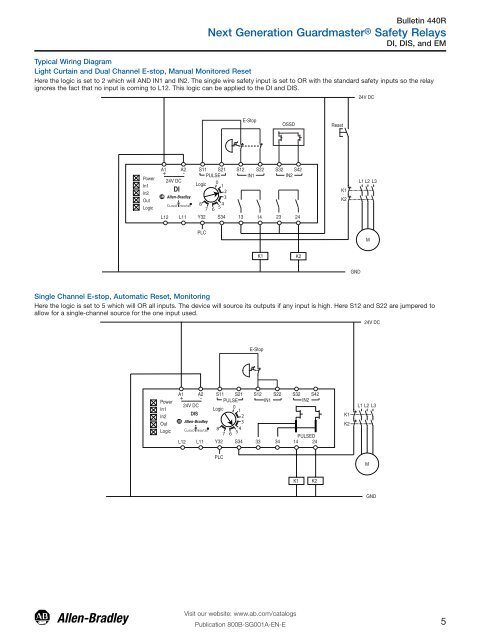
Typical Wiring Diagram<br />
Light Curtain <strong>and</strong> Dual Channel E-stop, Manual Monitored Reset<br />
Here the logic is set to 2 which will AND IN1 <strong>and</strong> IN2. The single wire safety input is set to OR with the st<strong>and</strong>ard safety inputs so the relay<br />
ignores the fact that no input is coming to L12. This logic can be applied to the <strong>DI</strong> <strong>and</strong> <strong>DI</strong>S.<br />
Power<br />
In1<br />
In2<br />
Out<br />
Logic<br />
A2<br />
A1 + -<br />
L12<br />
24V DC<br />
<strong>DI</strong><br />
L11 Y32<br />
S11 S21 S12 S22 S32 S42<br />
PULSE<br />
0<br />
1<br />
IN1<br />
IN2<br />
8<br />
7 6<br />
2<br />
3<br />
4<br />
5<br />
Logic<br />
PLC<br />
Single Channel E-stop, Automatic Reset, Monitoring<br />
Here the logic is set to 5 which will OR all inputs. The device will source its outputs if any input is high. Here S12 <strong>and</strong> S22 are jumpered to<br />
allow for a single-channel source for the one input used.<br />
Power<br />
In1<br />
In2<br />
Out<br />
Logic<br />
E-Stop<br />
K1<br />
OSSD<br />
S34 13 14 23 24<br />
A1 A2<br />
+ -<br />
24V DC<br />
<strong>DI</strong>S<br />
S11 S21<br />
PULSE<br />
0<br />
1<br />
2<br />
3<br />
S12 S22<br />
IN1<br />
S32 S42<br />
IN2<br />
8<br />
7 6<br />
4<br />
5<br />
PULSED<br />
L12 L11 Y32 S34 33 34<br />
14 24<br />
Logic<br />
PLC<br />
E-Stop<br />
K2<br />
K1<br />
K2<br />
Reset<br />
K1<br />
K2<br />
K1<br />
K2<br />
GND<br />
24V DC<br />
L1 L2 L3<br />
M<br />
24V DC<br />
L1 L2 L3<br />
M<br />
GND<br />
5