Memorandum - NHTSA
Memorandum - NHTSA
Memorandum - NHTSA

Create successful ePaper yourself
Turn your PDF publications into a flip-book with our unique Google optimized e-Paper software.
Subject:<br />
From:<br />
To:<br />
U.S.Department<br />
of Transportation<br />
NationalHighway<br />
Traffic Safety<br />
Administration<br />
<strong>Memorandum</strong><br />
ACTION: Final Regulatory Evaluation Date:<br />
Platform Lift Systems for Motor Vehicles NOV 27 3332<br />
FMVSS Nos. 403 and 404<br />
L-FLd 6-<br />
Rose A. McMurray<br />
Associate Administrator<br />
for Planning, Evaluations and Budget<br />
Chief Counsel<br />
’7<br />
Reply to<br />
Attn. of:<br />
Please submit the attached copy of the “Final Regulatory Evaluation and Regulatory<br />
Flexibility Analysis, Platform Lift Systems for Motor Vehicles FMVSS Nos. 403 and 404”<br />
to the appropriate docket.<br />
Attachment<br />
Distribution:<br />
Chief Counsel<br />
Associate Administrator for Rulemaking<br />
Associate Administrator for Enforcement<br />
Associate Administrator for Applied Research<br />
SAFETY BELTS SAVE LIVES<br />
#
U.S. Department<br />
Of Transnortation<br />
People Saving People<br />
http://www.nhtsa.dot.gov<br />
FINAL REGULATORY EVALUATION AND<br />
REGULATORY FLEXIBILITY ANALYSIS<br />
PLATFORM LIFT SYSTEMS FOR MOTOR VEHICLE!$<br />
FMVSS NOS. 403 AND 404<br />
Office of Regulatory Analysis and Evaluation<br />
Plans and Policy<br />
May 2002
TABLE OF CONTENTS<br />
Summary............................................................................................................ 5-1<br />
1. Introduction ................................................................................................ I- 1<br />
11. Background ................................................................................................ 11-1<br />
...............................................................................................<br />
111. Safety Need 111-1<br />
IV . Final Rule Requirements .......................................................................... Iv-1<br />
V . Benefits ...................................................................................................... v-1<br />
VI. Cost ........................................................................................................... v1-1<br />
VI1. Lead Time............................................................................................... v11-1<br />
VI11.Regulatory Flexibility Analysis ............................................................ VIII-1<br />
References<br />
Appendix
EXECUTIVE SUMMARY<br />
s-1<br />
On July 26, 1990, the President signed into law the Americans with Disabilities Act (ADA) of<br />
1990 (P.L. 101-336,42 U.S.C. 12101, et seq). Title I1 of the ADA requires newlypurchased,<br />
leased or remanufactured vehicles used in fixed route bus systems to be readily accessible to an.l<br />
usable by individuals with disabilities, including individuals who use wheelchairs. Title 111<br />
requires public transportation services from private entities to be readily accessible to and usable<br />
by disabled individuals, including individuals who use wheelchairs.<br />
The Act states that the Secretary of Transportation is required to promulgate implementing<br />
regulations for public transit and paratransit buses. <strong>NHTSA</strong> was designated by the Secretary to<br />
establish minimum safety requirements for lift-equipped buses for use by disabled persons in tk e<br />
public transportation environment. These lifts are to be used by people who cannot walk up<br />
stairs, people who use a cane or walker, and people in wheelchairs.<br />
FMVSS Nos. 403/404 addresses minimum vehicle safety requirements applicable to lift<br />
equipment designed for purchased, leased or remanufactured transit buses (fixed route),<br />
paratransit buses, and vans (demand response route) as well as personal vansMPVs, school<br />
buses, over-the-road buses (including remanufactured OTRB) and all types of vehicles equippcd<br />
with lifts. The lift equipment requirements are contained in FMVSS No. 403 and the vehicle<br />
requirements are contained in FMVSS No. 404. Although not required by the ADA, <strong>NHTSA</strong> is<br />
requiring that all motor vehicles, if lift-equipped, meet the minimum safety performance<br />
requirements specified in FMVSS No. 403.
s-2<br />
The annual number of persons injured in lift-equipped bus and van incidences in NEISS is smi 11<br />
248 per year. The agency has not been able to quantify the benefits associated with the Final<br />
Rule because the NEISS accident data lacks adequate and sufficient descriptive information<br />
needed to pinpoint the probable cause of injury. However, there are a number of qualitative<br />
benefits associated with the Final Rule that incorporates the most relevant requirements of<br />
industry standards and guidelines (e.g., Disabled Veterans Administration, Society of<br />
Automotive Engineers and Federal Transit Authority.) Thus, manufacturers need only comply<br />
with one standard rather than several, which will provide a consistent level of safety for all lift<br />
users. The Final Rule sets minimum safety standards for lifts. In addition, the Final Rule<br />
addresses the injury mechanisms that have been identified by the agency.<br />
The total consumer cost of the Final Rule is estimated to be between $3.1M - $4.7M per year.<br />
This was based on cost of $213 per vehicle for (8,288-10,425) Public-Use vehicles, and a cost of<br />
$147 per vehicle for (8,800-17,000) Private-Use vehicles.
y the Secretary to establish minimum safety requirements for lift-equipped buses for use by<br />
1-2<br />
disabled persons in the public transportation environment. These lifts are to be used by peoplt'<br />
who cannot walk up stairs, people who use a cane or walker, and people in wheelchairs. NHT'SA<br />
published an NPRM February 26, 1993 (See 58 CFR 11562) entitled Lifts for Accessible<br />
Transportation, FMVSS No 401,which was a vehicle-based standard which included transit<br />
buses, paratransit buses, and school buses, but excluded personal vans/MPVs, trucks, truck<br />
tractor, motor homes and over-the-road-buses (OTRB). In the July 27,2000 SNPRM (65 CFF<br />
46228) <strong>NHTSA</strong> proposed replacing FMVSS No. 401 with FMVSS No. 141 (a lift equipment<br />
standard) and FMVSS No. 142 (a vehicle standard). The agency has subsequently changed the<br />
proposed FMVSS Nos. 141 and 142 with FMVSS No. 403 Platform Lift Systems for Motor<br />
Vehicles and FMVSS No. 404 Platform Lift Installations on Motor Vehicles, in the Final Rule<br />
FMVSS Nos. 403/404 addresses minimum vehicle safety requirements applicable to lift<br />
equipment designed for purchased, leased or remanufactured transit buses (fixed route),<br />
paratransit buses, and vans (demand response route) as well as personal vans/MPVs, school<br />
buses, over-the-road buses (including remanufactured OTRB) and all types of vehicles equippc :d<br />
with lifts. The lift equipment requirements are contained in FMVSS No. 403 and the vehicle<br />
requirements are contained in FMVSS No. 404. Although not required by the ADA, <strong>NHTSA</strong> s<br />
requiring that all motor vehicles, if lift-equipped, meet the minimum safety performance<br />
requirements specified in FMVSS No. 403.
11. BACKGROUND<br />
11- 1<br />
Guidelines pertaining to accessibility by the disabled to public transportation were prepared bj<br />
the Architectural and Transportation Barrier Compliance Board (ATBCB), which is also refen ed<br />
to in this regulatory evaluation as the Access Board.' DOT incorporated the Access Board's<br />
guidelines, requiring compliance with them in a final rule establishing accessibility guidelines.<br />
<strong>NHTSA</strong>'s Final Rule has adopted most of the Access Board's lift performance guidelines (Le.,<br />
platform size, lift capacity, slip resistance, safety interlocks. edge guard heights, etc.), but<br />
because of the need for objectivity and reproducibility, has expanded some of those<br />
requirements, where necessary, to include further delineation and specificity (ie., load levels,<br />
load directions, load application points, time durations, diniensions, etc.) necessary to support<br />
compliance tests (Le., deflection test, working load test, proof load test, ultimate load test,<br />
dynamic outer barrier and overload test, inner roll stop load test, slip resistance test, hand rail<br />
test, etc.). By law, a Federal motor vehicle safety standard has to meet the need for safety and >e<br />
stated in "objective" terms [(15 USC 1392 (a)]. Being stated in "objective" terms assures that he<br />
lift or bus manufacturers can interpret the requirements without ambiguity and that the propost d<br />
tests are reproducible (e.g., can be conducted in a similar manner regardless of the manufacturc r<br />
or test facility location).<br />
1 36 CFR Part 1192 - Americans with Disabilities Act (ADA) .4ccessibilitv Guidelines for Transportatior<br />
Vehicles, Proposed Guidelines, Subpart B - Large Buses and Systems (GVWR greater than 19,500 lbs.) and Subr art<br />
G - Vans and Small Buses (GVWR less than or equal to 19,500 lbs.), prepared by the Architectural and<br />
Transportation Barriers Control Board (ATBCB), 56 FR 11824-1 187 1. Also see Final Guidelines, Subpart B-Bu.:es,<br />
Vans and Systems (56 FR 45529-45581) and 49 CFR Parts 27, 37,and 38, Transportation for Individuals with<br />
Disabilities, Final Rule, Department of Transportation (DOT)(56 FR 45584-454804)
11-2<br />
In developing the Final Rule, <strong>NHTSA</strong> has relied extensively on the Access Board and Federal<br />
Transit Administration (FTA) sponsored guidelines, as well as standards and recommended<br />
practices/procedures of other organizations, such as the Department of Veteran Affairs (DVA)<br />
[formerly the Veterans Administration (VA)] and the Society of Automotive Engineers<br />
(SAE).2,&,3The DVA requirements and the SAE draft recommended practices are intended foi,<br />
the private, personally-licensed lift user (e.g., a disabled person with a modified van or MPV).<br />
The Access Board's guidelines were adopted from FTA sponsored active and passive lift<br />
guidelines, and are believed to reflect the capabilities of lift equipment on the market today. The<br />
FTA guidelines were developed by a large panel of regulators; transit bus owners/operators; ussrs<br />
and bus manufacturers in the 1986-87 time <strong>NHTSA</strong> added requirements beyond the<br />
Board's guidelines that are based on the FTA guidelines. Most lifts are currently being market(:d<br />
and designed around the FTA's guidelines, and the improvements required by <strong>NHTSA</strong> in the<br />
Final Rule are not expected to increase lift costs significantly.<br />
The agency identified a number of reasonable safety improvements in the SNPRM, not contair ed<br />
in the Access Board's guidelines. These improvements include: upgraded outer barrier height<br />
2 VA Standard Design and Test Criteria for Safetv and Quality of Automotive Wheelchair Lift Systems fig<br />
Passenger Motor Vehicles, VAPC-A-7708-3, June 28, 1977<br />
3National Workshop on the Bus-Wheelchair Accessibility, Guideline Specifications for Active Wheelchllir<br />
(WC) Lifts, Passive WC Lifts, WC Ramps, and WC Securement Device ,UMTA Publication-UMTA-ITO6-0322-87,<br />
May 1986<br />
4 National Workshop on the Bus-Wheelchair Accessibility, Guideline Specifications for Active Wheelchiiir<br />
(WC) Lifts, Passive WC Lifts, WC Ramps, and WC Securement Device ,UMTA Publication-UMTA-IT06-0322.87,<br />
May 1986
11-3<br />
and strength; control panel lettering size and illumination; high contrast platform markings for<br />
standees; threshold warning device; anti-crush interlock; outer barrier and inner roll stop<br />
interlock devices; and a bridging interlock device. The final rule included all these<br />
improvements except for the anti crush interlock and the bridging interlock device. The SNPR M<br />
also proposed a number of safety tests, which include: slip resistance test; wheelchair retentioi i<br />
test; handrail test; corrosion resistance test; and fatigue endurance test. In no area did the agen,:y<br />
propose a less stringent requirement than specified by the Access Board.
111. SAFETY NEED<br />
111-1<br />
Although some of the Final Rule requirements can be justified on the basis of accident and inj iry<br />
data, the agency's rule is based on Access Board and FTA sponsored guidelines and<br />
recommendations as well as SAE practices and procedures. The FTA sponsored guidelines wj :re<br />
developed in consultation with bus drivers and transit system operators and reflect engineering<br />
judgment and common practice. The requirements being proposed are consistent with those<br />
published by many organizations concerned with bus lift systems for the disabled, e.g., the FT.1,<br />
the Department of Veteran Affairs (DVA), the Society of Automotive Engineers (SAE).<br />
<strong>NHTSA</strong> estimates 1,238 lift-related accidents and injuries occurred in vehicles covered by this<br />
Final Rule (vans and buses) in 1991-95 or 248 injuries per year. <strong>NHTSA</strong> analyzed the most<br />
recent NEISS data (1991-95) from the Consumer Product safety Commission concerning the<br />
incidence of lift-related accidents and injuries and found 972 and 266 incidences for vans and<br />
buses, respectively, compared to the same data studied in 1986-90 which found 381 and 140<br />
incidences, respectively.' All things being equal, the agency believes there has been an<br />
increasing trend in lift-related injuries of 2.5 X and 1.9 X, respectively, for vans and buses for<br />
these two five year increments of time. <strong>NHTSA</strong> believes the increase is due to increased<br />
ridershiphage due to the ADA and not a decrease in lift safety. The agency can not pin point<br />
the cause of these particular lift-related incidences, whether lift operator or equipment related.<br />
1 Wheelchair Users Injuries and Deaths Associated with Motor Vehicle Related IncideIits,<br />
Research Note, September 1997,National Center for Statistics and Analysis, Research and<br />
Development, <strong>NHTSA</strong>, 400 7thStreet SW, Washington, DC 20590. Also see School Transport<br />
News, February 1998, for same data page 1 and page 18.
111-2<br />
Generally, there is very little information regarding WC lift accidents and injuries. Very few lj ft<br />
related accidents or injuries can be associated directly with the requirements except by anecdo1:al<br />
information or defect investigations conducted by the agency. <strong>NHTSA</strong> has conducted a few<br />
defect investigations concerning WC lifts in the 10-12 years prior to the SNPRM. The<br />
commenters presented little, if any, lift user injury data (WC user or otherwise). A recent TRP:<br />
article on tort liability arising out of the ADA shows that for the 1991- 1995 period there have<br />
been a limited number of tort claims, out of millions of fare trips, filed against a sample of 43<br />
transit companies involving disabled riders involving wheelchairs.* WC lifts were not implicz ted<br />
as a source of injury or the subject of a tort in this study.<br />
Since implementation of the ADA, there has been a doubling in “disabled riders” from 7,534,002<br />
(1991) to 16,839,291 (1995) based on the responses of 43 transit agencies responding to a TCIP<br />
survey. For the same agencies (1991-1995), WC ridership, based on the number of trips,<br />
increased by a factor of 5 [from 298,912 (1991) to 1,498,395)].3 There are 6,000 agencies that<br />
provide public transportation in the U.S. and they have probably experienced similar increases.<br />
Although the number of WC related tort claims increased for the same 43 agencies from 1 to 2 7<br />
from 1991 to 1995, liftshamps are not mentioned as a source of injury or a tort liability issue.<br />
* Potential Tort Liability for Transit Agencies Arising Out of the Americans with<br />
Disabilities Act, Transit Cooperative Research Project (TCRP), Legal Research Digest, No 11 ,<br />
July 1998, Transportation Research Board (TRB), National Research Council.<br />
Ibid
111-3<br />
<strong>NHTSA</strong>'s large scale, nationally representative accident data bases (FARS, NASS) do not revc :a1<br />
any bus lift accidents or injuries as these data systems are used to record accident, injury and<br />
fatality information for vehicles in transport. Since lifts are operated only when the vehicle is not<br />
in transport, lift accidents and injuries are excluded from these databases.<br />
The agency reviewed the 1991-1995 WC user injury data from the Consumer Product Safety<br />
Commission, National Electronic Injury Surveillance System (MISS). This is considered to be<br />
a nationally representative database. Out of 7,121 WC injuries involving motor vehicles as<br />
shown in Tables 111-1 and 111-2,48percent involved vans and 12 percent involved buses (e.g.,<br />
school buses, transit buses and OTRB). The motor vehicle injury incidence types involving U Cs<br />
were as follows: 35 percent were WC securement related, 26 percent involved collisions with i<br />
motor vehicle, 19 percent (1,366/7,12 1) were lift related, 15 percent were related to transfemng<br />
to and from a WC and 6 percent were ramp related.<br />
The wheelchair lift-related injuries predominantly happen on lift-equipped vans (71 percent<br />
97211,366) and buses (19 percent 266/1,366). While passenger cars were involved in about (8<br />
percent 111/1366) of the incidents, and ambulances/ambulettes were involved in (1 percent<br />
17/1366) of the incidents. For these lift-related motor vehicle incidents, 3.1 percent resulted irl<br />
serious injuries while 69.5 percent were moderate and 27.3 percent were minor. Over 95 perccnt<br />
of WC incidents were reported in the category of "released without treatment," while the other 5<br />
percent were hospitalized. For ramps, 90 percent of the incidents involved vans and 10 percen t<br />
automobiles.
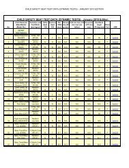
111-4<br />
Table 111-1<br />
Preliminary Nationwide Estimate of Wheelchair Occupants<br />
Injured in Motor Vehicle-Related Incidents<br />
By Type of Wheelchair Incident and Body Type of Motor Vehicle<br />
NEISS Data Files: 1991-95<br />
Body Type of Motor Vehicle(1) 1 Total Wheelchair<br />
OccupaIit<br />
TypeofWheelchairIncident 1 Auto I Van 1 Bus 1 Ambulance<br />
Securement(2) 0 1,617 422 455 0 2,494<br />
- nodimproper securement 0 1,478 422 402 0 2,302<br />
- securement unknown 0 139 0 53 0<br />
192<br />
Collision with MV 1,511 122 34 0 152 1,819<br />
Hydraulic Lift 111 972 266 17 0 1,366<br />
Transferring(3) 488 335 134 34 44 1,035<br />
RaIllD<br />
TOTAL 1<br />
43<br />
2,153 I<br />
364<br />
3,410 I<br />
0<br />
856 1<br />
0<br />
506 1<br />
0<br />
196 I<br />
407<br />
'7,121<br />
Total Wheelchair Incidents 1991-95(4) 299,':34<br />
Source: U.S. Consumer Product Safety Commission<br />
(1) Ambulance category includes ambulettes.<br />
(2) Refers to securement within the vehicle; either the assisted or unassisted by others, generally without lift or<br />
ramp involvement.<br />
(3) While transferring to or from a motor vehicle, either assisted or unassisted by others, generally without liIt<br />
or ramp involvement.<br />
(4) All wheelchair cases whether motor vehicle-related or not such as falling out of the wheelchair or injured<br />
while in it, at home, in resident institutions, outdoors, etc.
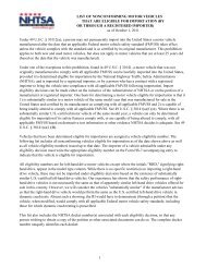
111-5<br />
Table 111-2<br />
Preliminary Nationwide Estimate of Wheelchair Occupants In -ed in Motor Vehicle Related Incidents<br />
By Type of Wheelchair Incident, Severity of Inju and Medical C )ositton of Case Neiss Dz Files: 1991 -95<br />
Medic Disposition of se -~<br />
Injury Severity Treated & Hospitalized Fatality Total Cases Percent of Total<br />
Released<br />
All Five Types<br />
Minor Injuries 1,826 .34 c 1,860 26. I<br />
Moderate Injuries 4,335 365 c 4,703 66.1<br />
Serious Injuries 225 290 c 515 7.2<br />
Died( 1) 0 0 43 43 0.6<br />
Total 6,386 692 43 7,121 100.0<br />
Yo 89.7 9.7 0.6 100.0<br />
Securement<br />
Minor Injuries 705 0 0 705 28..3<br />
Moderate Injuries 1,435 112 0 1,607 64.4<br />
Serious Injuries 122 60 0 182 7.3<br />
Died( 1) 0 0 0 0 0<br />
Total 2,262 232 0 2,494 100<br />
% 90.7 9.3 0<br />
-~ 100.0<br />
Collision with Motor Vehicle<br />
Minor Injuries 532 34 0 568 31.2<br />
Moderate Injuries 831 120 0 95 1 52.3<br />
Serious Injuries 103 154 0 257 14.1<br />
Died( I ) 0 0 43 43 2.4<br />
Total 1,468 308 43 1,819 100.0<br />
% 80.7 16.9 2.4 100.0<br />
Hydraulic Lift<br />
Minor Injuries 373 0 0 37 27.3<br />
Moderate Injuries 933 17 0 950 69.5<br />
Serious Injuries 0 43 0 43 3.1<br />
Died( 1) 0 0 0 0 0<br />
Total 1,306 60 0 1,366 100.0<br />
% 95.6 4.4 0 100.0<br />
rransferring<br />
Minor Injuries 128 0 128 12.4<br />
Moderate Injuries 815 59 874 84.4<br />
Serious Injuries 0 33 33 3.2<br />
Died( 1) 0 0 0 0<br />
rota1<br />
% 1<br />
943<br />
91.1<br />
92<br />
8.9<br />
1,035<br />
100.00<br />
111-6<br />
The NEISS database lacks the necessary detail in order to identify the lift malfunction type/mc\de<br />
or the operator failure modes responsible for each accident. <strong>NHTSA</strong> also examined the NEIS!;<br />
Death Certificate file from July 1973 to present and identified two fatalities involving wheelcf air<br />
lifts; (1) the occupant fell from the wheelchair on a hydraulic lift while boarding a bus<br />
(1 1-21-8l), (2) the wheelchair occupant was pinned under the van's hydraulic lift (5-17-90). P,<br />
national estimate of lift related fatalities can not be extrapolated from these two cases. In the<br />
1991-95 NEISS study, 12 wheelchair users died in motor-vehicle related incidences, but none<br />
involved a lift malfunction or falling on to/off of a ramp (e.g., 9 involved a direct collision<br />
between a wheelchair and a motor vehicle, 2 were from improper or no WC securement and 1<br />
was from transferring to or from a motor vehicle).<br />
<strong>NHTSA</strong>'s Office of Defects Investigation (ODI) has reported two cases in 1985 and 1989<br />
(EA85030 and PE89-144) in which accidents occurred on bus lifts due to operator and<br />
maintenance error. In the first case, the lift operator accidentally tried to stow a passive lift wi .h<br />
the disabled user still on the lift. For a passive lift, the platform is converted to steps when in 1 he<br />
stowed position. The lift user was thrown to the pavement and died from serious injuries. As a<br />
result of this accident, the passive lift manufacturer built-in a load sensing device to prevent<br />
premature stowage. In the second OD1 case, the automatic outer barrier malfunctioned and thcr<br />
wheelchair and its occupant tumbled off the lift onto a pedestrian standing next to the lift. Bo1h<br />
persons were hospitalized. The problem was caused by insufficient outer roll stop maintenance.<br />
Maintenance practices were subsequently modified to include more periodic inspection intends.
111-7<br />
Personal Use Vehicles - The National Mobility Equipment Dealers Association (NMEDA)<br />
estimates 20,000 vehicles of all types (e.g., automobiles, vans, trucks etc.) are modified with<br />
adaptive driving equipment annually by some 450 conversion companies. According to the<br />
Census Bureau, 4 percent of Americans ages 17 - 75 or some 7.3 million people, have physical<br />
disabilities that limit their m~bility.~ About half of these people use wheelchairs, scooters, or<br />
other mobility devices. The Exemption from Make Lnoperative Prohibition WRM (63 FR<br />
51547, September 28, 1998) estimated that there are about 383,000 vehicles on U.S. roads<br />
modified with adaptive equipment to accommodate persons with di~abilities.~Some percentaj ;e<br />
of these vehicles are personal use vehicles, equipped with lifts and ramps. Based on a United<br />
Kingdom figure of 250,000 disabled drivers (See Automotive Engineering Lnternational, Marc 1<br />
1998), the agency extrapolates there could easily be over 1 million disabled drivers in the U.S.<br />
population. The proportion of personal vehicles lift-equipped is unknown, and the number of<br />
WC users who drive (and need a lift) is unknown and the number of wheelchair users who are<br />
passengers (and need a lift) is unknown.<br />
4 “In a Wheelchair and Behind the Wheel,” Specialty Market Magazine, September 20,<br />
1998. New York Times Web Site.<br />
“Estimating the Number of Vehicles Adapted for Use by Persons with Disabilities,”<br />
<strong>NHTSA</strong> Research Note, January 1997, NCSN <strong>NHTSA</strong>.
111-8<br />
Public Transit & Paratransit Buses - According to the APTA, some 6,000,000 people use tran,d<br />
buses on a typical weekday. Of these, about 1.2 percent or 72,000 are estimated to have<br />
disabilities6 In addition, it is estimated there are 1,411,000wheelchair users, 64,000 users oj’<br />
scooters, 1,687,000 users of walkers, and 5 million users of canes/crutches in the U.S. all of<br />
which could potentially use lifts on public transportation vehicles.’<br />
American Public Transit Association, APTA 1997 Fact Book<br />
“Assistive Technology Devices and Home Accessibility Features: Prevalence, Payme it,<br />
Need and Trends,” La Plante, M.P., Hendershot, G.E., and Moss, A.J., National Center for Health<br />
Statistics, Hyattsville, MD 1992.
IV. FINAL RULE REQUIREMENTS<br />
Iv-1<br />
There are two types of lifts: passive and active. In transit-type buses, where passive type lifts ire<br />
typically used, the lift is often located in the front door so that disabled and non-disabled persons<br />
can use the same service door. In this case, the steps can be converted to a horizontal lifting<br />
surface. The width of the service door structure constrains the width of the passive lifts that c;in<br />
be installed (e.g., if the lifts are too wide the transit buses would have to be redesigned).<br />
In active lift systems, the lift is separate from the front service door (typically in the right side,<br />
rear of paratransit and school buses) and there is much greater flexibility in the widths of the li fts<br />
that can be installed. When folded into the stowed position, this lift normally blocks the door in<br />
which it is installed. For both lifts types, the operator is within very close visual range of the lift<br />
user when operating the controls. The agency believes that the same level of safety is needed or<br />
both active and passive lifts.' Figures 1,2 and 3 in the Appendix show the basic lift<br />
components and terminology to be used in the subject regulatory evaluation, while Figures 4 and<br />
5 in the Appendix show the basic wheelchair dimensions and terminology used in sizing the li I-t<br />
platform.2 In addition, a diagram of a Braun lift has been added to the Appendix of this reporl.<br />
' Active Lift - The lift is located in a separate doorway, other than the service door, suc h<br />
as a right-rear side door of a paratransit bus or school bus. Passive Lift - The lift is located in he<br />
service door opening of the transit bus. The service door steps convert to a horizontal lifting<br />
surface.<br />
* Preliminary Regulatory Evaluation, Lift Systems for Accessible Transportation, FM\ SS<br />
No. 401, November, 1992, National Highway Traffic Safety Administration, Office of<br />
Regulatory Analysis, Docket No. 91-19-NO1-002.
w-2<br />
identifying the relevant lift components and parts. The purpose of this section is to summarin<br />
each part of the agency's Final Rule and to: (1) provide a rationale or justification for each<br />
requirement in the Final Rule, particularly the objective performance measures, (2) identify<br />
where the agency's Final Rule differs from the Access Board's final guidelines, (3) delineate<br />
where lift manufacturers currently & or do not meet the specifications, and (4) identify each a 'ea<br />
where costs may be incurred by either the lift or bus manufacturers. The costs will be quantifi .:d<br />
in Section VI. Cost.<br />
Applicability - FMVSS No. 403, the equipment standard, divides the applicable safety<br />
requirements into two basic categories. The first category applies to lifts designed for installat ion<br />
on MPVs, except for motor homes, with a GVWR >4,540 kg (10,000 lbs.) and buses. This<br />
category applies to lifts for commercial and public-use vehicles including transit buses,<br />
paratransit buses, school buses and most paratransit MPVs. The second category applies mostly<br />
to lifts designed for installation on MPVs intended for personal use. There are fewer<br />
requirements for personal use vehicles, as hand rails, platform volume/size, lighting, platform<br />
marking, inner roll stop, controls illumination requirements do not apply and fatigue enduranc ;<br />
requirements have been reduced. However, there is an exception. There is an optional inner<br />
roll stop requirement for lifts designed for personal use vehicles [
Performance Requirements<br />
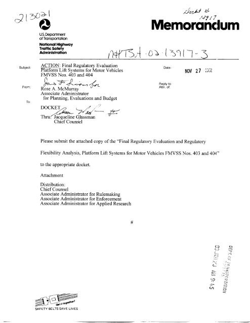
1. Threshold Warning Signal (S6.1)3<br />
rv-3<br />
This requirement is designed to warn deboarding lift users, at the lift door, that the lift platfonil is<br />
not at vehicle floor level. Located on the floor of the transit or paratransit bus at the lift door<br />
opening, the platform threshold area is 457 mm (18 in.) deep measured from the edge of the li it<br />
door and as wide as the lift door. Except in cases where the platform is loaded over the vehicl,:<br />
floor such as with a personal rotary lift, a visual or audible warning is to activate: (1) if portions<br />
of a passenger’s body or mobility aid is on the “platform threshold area” and (2) if the lift<br />
platform is more than 25 mm (1”) below the “floor reference plane”. Once a warning signal is<br />
activated, it must continue to operate until the “platform threshold area” is vacated, or the lift i!;<br />
returned to the vehicle floor level. (See Figure IV-1)<br />
If a visual warning is used to comply (S5.1.l), it is to consist of a flashing red beacon with 20<br />
candela (minimum) power and be visible to a wheelchair user backing onto the lift. The flash<br />
rate specified by (S6.1.4) is between 1 to 2 Hz. Typically, the warning light would be located<br />
inside the bus or MPV inside the lift door opening. The warning beacon accommodates heariiig<br />
impaired and deaf pedestrians standing near the lift. The red beacon’s intensity is to be measur,:d<br />
914 mm (3’) above the centroid of the platform threshold area as shown in Figure IV-1.<br />
The alpha-numeric in parentheses refers to the pertinent section of the regulatory text
IV-4<br />
MEASURE RED FLASHING<br />
BEACON OR MEASURE AUDIBLE<br />
WARNING 2 85dBA -\<br />
LIFT REFERENCE PLANE<br />
PLATFORM<br />
THRESHOLD<br />
AREA<br />
CENTROID<br />
PLATFORM THRESHOLD<br />
AREA (SHADED)<br />
LIFT DOOR EDGE -<br />
FLOOR k<br />
-LIFT PLATFORM CENTERLINE<br />
I t- I<br />
%3<br />
I<br />
I<br />
\ I<br />
LIFT DOOR<br />
WIDTH, W<br />
PLATFORM THRESHOLD AREA AUDIBILE<br />
WARNING MEASUREMENT POINT (S5.L )<br />
FIGURE IV-1
v-5<br />
If an audible warning is used to comply (S6.1.2), the intensity of the audible warning (>=85 dl 3A<br />
@ 500-3000 Hz) is to be measured at 914 mm (3') above the center of the "platform thresholc<br />
area." The audible warning signal is continuous until the lift user vacates the platform threshc Id<br />
area. Threshold Warning Simal (S6. l), is currently contained in SAE personal lift requiremeii ts,<br />
but would be new for transit and paratransit buses. This type of warning is important in the<br />
public transportation environment where a lift might be sequentially used by several patrons ai id<br />
it is important to personal vans particularly if the lift is rear mounted and the user backs on to he<br />
lift. This requirement does not apply to rotary lifts because their lift platform is rotated over tile<br />
van/MPV's floor when being loaded.<br />
2. Lift Operational Requirements 66.2)<br />
Maximum Velocitv (S6.2.2) and Acceleration 66.2.3) - This requirement is concerned with tl-e<br />
maximum allowable operating velocity and acceleration of the lift, both horizontally and<br />
vertically, as well as the lift stowage/deploy velocities. The operating velocities and<br />
accelerations are measured unloaded and loaded (0 lbs. and 272 kg mass (600 lbs.)), respectively.<br />
The stowage/deploy velocities are measured unloaded. The vertical and horizontal velocity<br />
components of the lift platform are not to exceed 152 mm/s (6 ids) horizontally or vertically :md<br />
the acceleration of the platform is not to exceed 0.30 g's horizontally or vertically. The<br />
horizontal/vertical components of the stow/deploy velocity are not to exceed 305 "/s (12 in.'s).
IV-6<br />
Acceleration is to be measured per SAE 521 1, October 1988, with a CFC filter requirement oj’FH<br />
= 3 Hz and FN= 5 Hz. The accelerometer for this test is located at the centroid of the lift<br />
platform. <strong>NHTSA</strong> studied the applicability of the CFC 60 filter proposed in the NPRM and<br />
determined that it was insufficient. They studied existing University of Virginia (UVA) and<br />
VRTC data and determined that a CFC 3 filter was sufficient to attenuate the acceleration signal<br />
to a level below the 0.3 g’s limit and, therefore, is recommended for use. A copy of the <strong>NHTSA</strong><br />
study entitled “Determinationof Electronic Filtering for Post-Processing of Wheelchair Lift<br />
Acceleration Data, June 1996” has been placed in the Docket No. <strong>NHTSA</strong>-98-4511.<br />
These minimum performance requirements are consistent with the Access Board’s guidelines.<br />
The speed and accelerations are designed to be compatible with existing equipment and shoulc 1<br />
not place a new design requirement on lift manufacturers.<br />
Interior Maximum Operating Noise Level (S6.2.4) - This requirement sets a maximum lift<br />
operating noise level of 80 dBA inside the bus at a fixed operator position or in the area of the lift<br />
platform, during the lift operating cycle. This will allow for the communication of instruction,;<br />
between the lift operator and lift user (or vice versa) during both normal and emergency lift us,:.<br />
Assuming a maximum communication range of 913 mm (3’) (which should be sufficient durin g<br />
lift operation), 80 dBA would be the maximum allowable lift operating noise. (See VRTC<br />
reference Human Factors Design Handbook, Second Edition, W.E. Woodson, B. Tillman, and P.
IV-7<br />
Tillman and Figure W-2taken from that referen~e).~Measurements are to be made at the fixc:d<br />
operator position at the lift controls and anywhere on the lift platform.<br />
VRTC measured 85 dBA ambient noise at 305 mm (1’) from a Braun Lift electric motor and 7 3<br />
dBA and 75 dBA, respectively, for a TMC bus lift being raised and interior ambient noise wit1 L<br />
the engine running. Also, VRTC measured the ambient noise levels at 6 bus stops and found iiin<br />
average of 79 dBA. The 75 dBA level has been used by the San Diego Transit Corporation in its<br />
lift specifications and was adopted by FTA in their guidelines for both passive and active lifts.<br />
The 85 dBA warning signal outside the bus would be completed within 4-8 seconds and woulcl.<br />
not interfere with, or contribute to, the 80 dBA maximum allowable equipment operating nois :<br />
level. This maximum noise level does not apply to the deploying or stowing aspects of the lif I.<br />
equipment when the lift platform is unoccupied. A maximum lift noise level is not contained<br />
the Access Board’s final guidelines. It is believed that all lift equipment would comply, hence 1 io<br />
cost impact is anticipated.<br />
4 The Vehicle Research and Test Center (VRTC) is located in East Liberty, OH and is<br />
part of <strong>NHTSA</strong>’s Office of Research and Development.
IV-8<br />
FIGURE IV-2<br />
:i<br />
a la<br />
Y<br />
t<br />
Permirlblo Dirtanco htwmon 8 Spoaku and Lidmnu8 ..<br />
Copied from H u m a n a n Haby<br />
W.E. Woodson, 8. Tillman. and p. Tillman<br />
Figure IV-2 Permissible Distance between a Speaker and a Listeners<br />
[Speaker to Listener Distance (feet) versus Ambient Noise Level dB(A). Reference: Human<br />
Factor Design Handbook, Second Edition, W.E. Woodson, B.Tillman and P. Tillman.]
v-9<br />
3. Platform Requirements (S6.4)<br />
Unobstructed Platform Operating Volume (S6.4.2) - The Final Rule requires that the lift<br />
platform have a minimum clear width of 762 mm (30 in.) measured from the platform surface to<br />
762 mm (30 in.) above the platform, and a minimum clear length of 1,219 mm (48 in.) measui ed<br />
from 5 1 mm (2 in.) above the surface of the platform to 762 mm (30 in.) above the surface of.he<br />
platform. This represents an unobstructed volume of length, width and height 1,219 X 762 X<br />
724 mm (48” X 30” X 28.5”). See Figure 6 in the Appendix.<br />
<strong>NHTSA</strong>’s unobstructed platform operating volume is based on the Access Board’srequiremenix<br />
The size of the lift platform was determined by the length and width of the population of<br />
wheelchairs-in-use and constrained by the known distance between structural members (A and B<br />
pillars) of doors in buses. In addition, at least 1,219 mm (48 in.) of length is also needed to<br />
accommodate three-wheeled mobility aids called “scooters” which are longer than most<br />
traditional wheelchairs and as long as the larger wheelchairs. <strong>NHTSA</strong>’s requirement is believt ,d<br />
to accommodate 90-95 percent of the wheelchair population and nearly 100 percent of the<br />
scooter population. This requirement is consistent with the Access Board’s guidelines.<br />
The requirements would apply to lifts on vehicles greater than 4,540 kg (10,000 lbs.) GVWR II.S<br />
these would be commercial vehicles serving the public with a variety of wheelchair/mobility ai.d<br />
sizes and configurations. No platform volume or size is required for MPV lifts or lifts on<br />
vehicles 4,540 kg (
IV-10<br />
and vehicle size. This requirement is consistent with the Access Board’s guidelines. All buse,;,<br />
except the ones with narrow entrance ways mentioned above, can accommodate a 762 X 1,21’1<br />
mm (30” X 48“)platform, hence, there is no FMVSS cost impact of this requirement.<br />
Platform Slip Resistance (S6.4.12 and S7.2) A minimum platform surface slip resistance of 0.65<br />
is required to prevent wheelchairs and people using walkers and canes from slipping on the<br />
platform’s surface, particularly when wet. A slip resistant surface reduces the accident potential<br />
for people standing on the lift and provides traction for a wheelchair. A performance test (S7.2)<br />
measures the slip resistance of the lift loading platform when wet using a friction block rather<br />
than a specific wheelchair design as proposed in the NPRM. The Friction Block Method<br />
proposed in the SNPRM and adopted in the Final Rule has been shown to be practicable,<br />
objective and repeatable.<br />
The Department of Transportation (DOT) regulations for disabled individuals are contained in 49<br />
CFR, Part 38 - Americans with Disabilities Act (ADA) Accessibility Specifications for<br />
Transportation Vehicles. Section 38.23(b) is concerned with vehicle lifts and states “...the<br />
platform surface shall be slip resistant.’’ The Federal Transit Administration=s (FTA)<br />
procurement guidelines for bus lifts also requires slip resistant surfaces. The Department of<br />
Veterans Affairs (DVA) standard for wheelchair lifts specifies that the lift platform surfaces must<br />
provide “adequate tire traction.” The same requirement is contained in the SAE draft standard<br />
for wheelchair lifts. However, none of the requirements stated above provide an objective test<br />
procedure for determining the adequacy of the slip resistance of the lift platform.
v-11<br />
During the development of an NPRM for vehicles with wheelchair lifts (previously called<br />
FMVSS No. 401), the agency proposed a procedure for measuring platform resistance in whkh a<br />
loaded power wheelchair would be placed on a wet, 30 degree inclined lift surface until sliding<br />
occurred. This was believed to occur at about a 0.60 coefficient of friction (COF).<br />
Unfortunately, testing at VRTC (Docket No. <strong>NHTSA</strong>-98-45 11) revealed that this was not an<br />
effective method because, in many cases, the wheelchair tipped over before sliding could occiir.<br />
Subsequently, VRTC staff conducted a literature search to determine other test procedures, wl iich<br />
might be useful in determining slip resistance and selected ANSVRESNA WC13 - 1991<br />
Determination of Coefficient of Friction of Test Surfaces for further investigation. <strong>NHTSA</strong><br />
proposed the ANSYRESNA WC13-1991 coefficient of hction (COF) test procedure with the<br />
following modifications:<br />
Procedural Changes to ANSYRESNA WC/13:<br />
1. The test surface area 450 X 100 mm (17.5" X 3.94") is horizontal and clean from dust, dirt ind<br />
debris.<br />
2. Pull the test block by a mechanical means to achieve a pull rate of 20 +/- 2 mm/s.<br />
3. Pull the test block for a minimum of 13 seconds and use only the last 10 seconds of force d;i.ta<br />
to calculate the average force, which is to have 2% accuracy in the 25N - 100 N range.<br />
4. Collect force data at a frequency of >= 10 Hz.<br />
5. The link between the test block and pulling mechanism shall have a stiffness>= 1 X lo5N/ItI.<br />
6. Evenly spray 3 ml(O.10 02.) of distilled water per 100 cm2(15.5 in2) of test surface area.<br />
Begin the test within 30 seconds of the water spray.
v-12<br />
7. Prepare test block fnction surface by lightly abrading with waterproof silicon carbide paper.<br />
grade P120, weight D (120 wet and dry).<br />
8. Pull the block in only one direction with pull force parallel to test sample surface.<br />
9. Determine the average pull force from a minimum of five trials over any area.<br />
10. Performance Criterion: Any area of a lift platform surface must have a coefficient of frictil )n<br />
>= 0.65 as measured by the test procedure.<br />
11. The lift surface can be tested in any direction using the test block and different surfaces on<br />
the same lift platform must meet the same minimum requirements.<br />
For further details on the lift platform COF test procedure, a report prepared by the agency ha:<br />
been placed in the docket (Docket No. <strong>NHTSA</strong>-98-45 11) entitled “Evaluation of ANSI/RESPdA<br />
WC/13 To Determine the Coefficient of Friction of Wheelchair Lift Platforms, June 6, 1996.”<br />
The Final Rule requires that a modified ANSI/RESNA WC/13 test procedure to determine the<br />
slip resistance or the coefficient of friction (pp)of WC lift platforms. The agency believes thal<br />
this procedure is objective, repeatable, practicable and meets the need for safety. In addition, t is<br />
believed that the majority of lifts currently marketed in the U.S. can meet or exceed the requirl :d<br />
0.65 value for pp,when the platform is wet. Platform Markings (S6.4.10) must be slip resistant<br />
as well. There could be multiple friction surfaces on a lift platform, therefore, the coefficient I )f<br />
friction must be>=0.65 anywhere on the lift platform surface including the platform markings.<br />
All lifts come equipped with neoprene rubber mats or other slip resistant surfaces and it is<br />
expected that industry would comply, as a whole, without changes or modifications.
N-13<br />
Platform Protrusions (S6.4.3) - Protrusions on the lift platform make it difficult for wheelchair<br />
boardinddeboarding. For an electric wheelchair, additional propulsive power may be needed o<br />
overcome a floor level obstruction, but the sudden acceleration could result in loss of control and<br />
an accident. <strong>NHTSA</strong> is proposing that when the lift's outer barrier (wheelchair retention devic :e)<br />
or inner roll stop is down, movement on or off the lift platform should be easy and uninhibited<br />
For buses and MPVs (>4540 kg (10,000 lbs.) GVWR), <strong>NHTSA</strong> is proposing in the SNPRM tllat<br />
lift platform surfaces are not to have protrusions which rise more than 6.5 mm (0.25") when<br />
measured perpendicular to the platform surface. For personal use vehicles, lift platform surfaces<br />
are not to have protrusions, which rise more than 13 mm (0.5") when measured perpendicular lo<br />
the platform surface. All portions of the sides of a protrusion that are between 6.5 mm (0.25")<br />
and 13 mm (0.50") above the platform are to have slopes not exceeding a 1:2 ratio.<br />
For buses and MPVs>4,540 kg (10,000 lbs.) GVWR, <strong>NHTSA</strong>'s SNPRM is consistent with all<br />
aspects of the ADA including for protrusion height. The Access Board has a 6.25 mm (0.25")<br />
maximum, which <strong>NHTSA</strong> has adopted. Lift manufacturers have indicated that mechanisms tc,<br />
hold the required outer barrier in-place may require protrusions through the lift platform when<br />
the outer barrier is up. Such protrusions would be allowable in the subject SNPRM. The Acc.:ss<br />
Board, FTA and SAE all have protrusion limitations and <strong>NHTSA</strong> is adopting the Access Board's<br />
specifications. All currently manufactured lift equipment would be expected to comply.
IV-14<br />
Gaps, Transitions and Openings (S6.4.4) <strong>NHTSA</strong> is concemed about vertical transitions<br />
entering or exiting the platform at the ground/floor levels, slopes between transitioning vertic: 1<br />
planes, vertical gaps, horizontal gaps, platform surface openings and edge guards gaps. Poor<br />
vertical transitions can be an impediment to power as well as manually operated wheelchairs. In<br />
addition, vertical gaps, which are too large, can impede boardingdeboarding passengers.<br />
The small tires of the wheelchair could get caught in horizontal gaps or platform openings. TI Le<br />
requirements are as follows:<br />
S6.4.4.1 Vertical Transitions - For ground level loading, the maximum vertical transition heig it<br />
is 6.5 mm (0.25") and for lift to bus floor transitions, the maximum vertical height is 6.5 mm<br />
(0.2 5'I).<br />
S6.4.4.2 Slopes - No vertical transition can be more than 6.5 mm (0.25") at either the ground or<br />
vehicle level. Horizontal gaps are limited to13 mm (0.50"). Between 6.5" and 13 mm (0.25"-<br />
0.50") rise, the platform or vehicle surface slope can not exceed a 1:2 ratio. Above a 13 mm<br />
(0.50") rise, the slope an not exceed 1:8 ratio. The total allowable rise is limited to 76 mm<br />
(3.0"). (See Figure IV-3 - Allowable Transition Dimensions and Slopes for Platform Entranc.:<br />
and Exit at Vehicle and Ground Level.)<br />
S6.4.4.3 Vertical Gaps - For the inner roll stop and outer barrier (eg, Wheelchair Retaining<br />
Device) in the upright, deployed position, the SNPRM defines a Block Test 15.9 X 15.9 X lo:?<br />
mm (0.625" X 0.625" X 4") where the long axis is held perpendicular to the "platform referen1:e
IV-15<br />
plane" to measure maximum allowable clearances. The block device can not pass between any<br />
gaps.<br />
S6.4.4.4. Horizontal Gaps - The SNPRM specifies that horizontal gaps are to be designed sucl I<br />
that they do not pass a sphere of 13 mm (0.50") diameter, with the lift at ground level or at flo )r<br />
level.<br />
S6.4.4.5 Platform Surface Openings - Some platforms employ steel mesh surfaces normally<br />
covered with a rubber mat. The exposed openings in the mesh can be an impediment to a<br />
wheelchair if too large. This Final Rule specifies that platform openings are to be designed such<br />
that they do not pass a sphere of 19 mm (0.75") diameter.<br />
S6.4.4.6 Edge Guards - The vertical gaps between the lift platform and the "moving" edge<br />
guards (those mounted to the platform structure) can not pass a sphere of 13 mm (0.50")<br />
diameter. For horizontal gaps between the lift platform and fixed edge guards (those mounted to<br />
the vehicle structure or lift frame) can not exceed a sphere of 6.5 mm (0.25") diameter.<br />
The maximum gap distances are to be measured when the lift is loaded with 272 kg mass (60C<br />
lbs.). <strong>NHTSA</strong> is adopting the Access Board's gap specifications and it is believed that all lift<br />
equipment can be installed to operate within these tolerances without further modifications or<br />
adjustments to either the lift design or installation. No additional manufacturer costs are<br />
anticipated due to this requirement.
Figure m-3 Allowable transition dimensions and slopes for platform<br />
entrance and exit at vehicle and ground level.
IV-17<br />
The DVA and the Access Board specify a 3 1.25 mm (0.62s") maximum vertical gap and 25 IT m<br />
(0.50") maximum horizontal gap between the lift and the bus body. The FTA-sponsored<br />
guidelines and SAE draft recommended practice all have maximum bus body to lift gap<br />
allowances.<br />
Platform Deflection (S6.4.5) - The Final Rule allows no more than 1.8 degree maximum lift<br />
platform deflection angle, measured relative to the bus floor, for the entire unloaded range of<br />
operation of the lift and 3 degrees maximum deviation from its unloaded position when loadec 1<br />
with 272 kg mass (600 lbs.). The angle is measured between an axis perpendicular to the lift<br />
platform surface and an axis perpendicular to the vehicle floor. The maximum allowable change<br />
in the angle is 4.8 degrees measured in any direction, between the axis perpendicular to the<br />
vehicle floor and platform reference planes when loaded with 272 kg mass (600 lbs.). The<br />
standee or wheelchair lift user's weight on the lift platform causes deflection of the lift relative, to<br />
the bus floor, similar to the deflection of a cantilever beam. Establishing a maximum platfom i<br />
deflection level assures stability for the user, particularly someone with a walker, and controls the<br />
ramp or grade of the lift so an unattended person can manually roll the wheelchair off the lift i nto<br />
the bus. Lift deflection is measured independent of bus roll. The agency believes that all<br />
personal and commercial lift products will pass the deflection test.<br />
Platform Edge Guard Height (S6.4.6) - Edge guards are low, fixed, vertical walls, which run<br />
along the length of both sides of the platform and prevent wheeled mobility aids from rolling,
IV-18<br />
sliding or being driven over the side of the platform. They are positioned parallel to the forward<br />
or rearward operating direction of the wheelchair and are designed to deflect the wheelchair's<br />
tires. <strong>NHTSA</strong> is requiring that during lift operation, the lift platform is to have continuous edl ;e<br />
guards parallel to the direction of loadinghnloading along each side. Edge guards mounted on<br />
the lift platform are to have a minimum height of 38 mm (1 SO") measured vertically from the<br />
platform. The previous section (S6.5.4.6) defined the maximum allowable vertical 13 mm<br />
(0.50") and horizontal gaps 6.5 mm (0.25") for fixed and moving edge guards. An edge guard<br />
requirement and minimum edge guard height are required by both the FTA-sponsored guidelines<br />
and the ADA standards (49 CFR 38.23(b)(5)).<br />
The California Administrative Code specifies a one inch minimum height for edge guards, wh ile<br />
the DVA and SAE have no requirement. The Access Board recommends 38 mm (1S")<br />
(minimum). A 38 mm (1SO") requirement, consistent with the Access Board's guidelines, is<br />
being adopted and applies to any part of the lift platform exposed or operated outside the<br />
perimeter of the bus. For example, an elevator type lift, operated entirely within the outside<br />
perimeter of the bus, would not need edge guards providing gaps between the side of the<br />
platform and the bus structure do not exceed gap requirements. All lift equipment currently iri<br />
production are expected to comply.<br />
9. Wheelchair Retention Device (S6.4.7, S7.7 and S7.13) - The outer bamer or wheelchair<br />
retention device of the platform is the only mechanical means which prevents the wheelchair<br />
from rolling, sliding or being driven inadvertently off the platform, when the platform is greater
IV- 1 9<br />
than 3 inches off the ground. The outer barrier is the only safety device which can prevent a<br />
wheelchair occupant from accidentally falling from a raised platform and research has shown<br />
electric wheelchairs are capable of climbing over some barriers which are in use today. Lifts ( an<br />
achieve a height of 40-50 inches off the ground, depending on the bus‘s floor height with the<br />
result that the top of the head of the wheelchair occupant could be a total of 90-100 inches off the<br />
ground. A fall could cause serious injury. All lifts are designed with a wheelchair retention<br />
device regardless of intended vehicle GVWR. The Final Rule requires a dynamic test,<br />
employing a WC test device, to prevent the WC from climbing over the outer barrier, and an<br />
overload strength test to prevent the WC crushing, bending or plowing-through for the<br />
wheelchair retention device.<br />
In their final guidelines issued September 6, 1991,the Access Board did not specify a safety twt<br />
for the outer barrier or WC retention device, but deferred to <strong>NHTSA</strong>’s expertise, as the agent!:<br />
was planning to issue proposed safety standards for lifts. In the Access Board’s final rule it is<br />
stated (pg. 45535), “...the Board feels that <strong>NHTSA</strong> is the appropriate agency to define safety<br />
tests .’,<br />
New WC Retention Test Method<br />
The WC Retention Device or outer barrier can be defeated by (a) WC climbing, (b) loss of<br />
strength and rigidity or (c) WC tipping. The WC retention device test is designed to address t le<br />
first two failure modes: (a) if traveling too fast, in the rearward direction, the large wheels of tine<br />
wheelchair can climb-up and over the outer barrier resulting in occupant injury and (b) if
v-20<br />
traveling too fast, in the forward direction, the smaller caster wheels can deform and bend the<br />
outer barrier such that the wheelchair could plow-through and off the lift platform also resultir g<br />
in occupant injury. Regarding Item (c) above, to prevent tipping would require a 12" - 15" or<br />
higher outer bamer, which would have been too cumbersome and impractical. Running the te ;t<br />
on an 8 degree incline as prescribed in the NPRM accentuated the tipping phenomenon, but di 1<br />
not cause the higher barriers to be climbed. The agency is requiring a dynamic WC test with zero<br />
ballast and a level lift platform in which a WC Test Device (S7.4.2) impacts the outer bamer :t<br />
approximately 4 mph in a forward or rearward direction and remains upright. This provides tl e<br />
most stringent test for bamer height. Because the dynamic WC Test Device only develops an<br />
impulse loading of 1,200 to 1,400 lbs., a separate 7,l I7 N (1,600 lbs.) static overload test (S6. IO)<br />
is also required for the outer barrier to ensure resistance to deformation, crushing or bending.<br />
The WC Test Device must operate under its own power with speeds of 2.0 - 2.1 m/s (4.4 - 4.7<br />
mph) in the forward direction and 1.75 - 1.80 m/s (3.9 - 4.1 mph) in the rearward direction at 1 he<br />
test vehicle floor level (without ballast or added weights). The footrests of the WC are raised 25<br />
mm (1 'I) above the top of the outer barrier. Despite spinning motion of the power wheels, the<br />
WC is to remain upright at the conclusion of the impact test. For lifts designed for buses and<br />
MPVs>4,540 kg GVWR, the tests are conducted in forward and rearward loading directions.<br />
For lifts designed for personal use vehicles
Iv-2 1<br />
both outer barrier retention devices are tested. For lifts designed for personal use vehicles<br />
WC Retention Overload Test 67.13)<br />
IV-22<br />
Deploy the outer barrier with the lift 89 mm (3.5”) above the ground. Apply 7,117 N (1,600 1k s.)<br />
and attain the load within 1 minute. If a rectangular outer barrier, the Ioad is to be distributed<br />
[area = 25 mm (1”) high by the width of the barrier face)] and centered 63 mm (2.5”) above thc<br />
platform surface. If the WC retention device is other than a conventional outer barrier design,<br />
apply the 7,117 N (1600 lbs.) directly to the WC test device (which would be pushed up agaimt<br />
the retention bamer. The WC retention device must maintain 7,117 N (1,600 lbs.) for 2 minulles<br />
without cracks, separations, fractures or breakage.<br />
For hrther details, the agency has placed in Docket No. <strong>NHTSA</strong>-98-45 11) an analysis entitled,<br />
“Wheelchair Retention Device Impact test Analvsis, June 6, 1996,” Also, the same docket sec an<br />
analysis entitled, “Determination of Center of Gravitv of Cross-Bar Frame Powered Wheelcha irs.<br />
June 6, 1996.”<br />
It is believed that very few, if any, lifts currently on the market would meet <strong>NHTSA</strong>’s dynamic,<br />
WC retention test in the loaded condition. Therefore ,it is believed all personal and commerc la1<br />
lifts would certify using the 7,117 N (1,600 lbs.) static overload test. Although all lifts curren ly<br />
manufactured have an outer barrier [at least 76 mm (3”) hi&], it is believed that they are of<br />
insufficient height to prevent WC climbing. VRTC found that 127-152 mm (5-6”) high barricr<br />
would be needed compared to the 76 mm (3”) barrier used on lifts today to prevent the<br />
wheelchair from climbing over the barrier given the test speed involved. Therefore, some<br />
consumer cost may be incurred to make the outer barriers 51 mm- 76 mm (2”-3”)higher. Thc
IV-23<br />
FTA guidelines recommend either a static or dynamic test. The Access Board has deferred to<br />
<strong>NHTSA</strong>'s expertise in establishing a viable outer bamer or retention device test.<br />
10. Inner Roll Stop Strength (S5.4.8 and S6.5) - In addition to a wheelchair retention device 01<br />
outer bamer, the proposed platform lift systems designed for buses and MPVs >4,450 kg (l0,CllOO<br />
lbs.) GVWR, are to have an Inner Roll Stop which prevents the wheelchair fiom inadvertently<br />
rolling or sliding off the inner edge (vehicle side) of the platform and prevents contact (pinchii 18)<br />
of occupant foot/toes between the WC lift platform and the vehicle structure. No inner roll stclp<br />
is required on personal use vehicles
IV-24<br />
The lift is raised to the floor level of the bus or MPV, and to conform to requirements, the innc:r<br />
roll stop must prevent the wheelchair test device from being pinched between the lift and any<br />
other structure (e.g., bus body or door structure) throughout the range of passenger operation.<br />
This simulates the potential for pinching of WC user feetkoes.<br />
For personal use vehicles 4,540 kg (10,000 lbs.) GVWR ir<br />
which case the lift must be able to be loaded with the WC in a forward or rearward direction,<br />
whereas for personal use vehicles
JY-25<br />
equipment currently on the market would be expected to comply without modifications or<br />
adjustments to the dynamic inner roll stop load requirements. It is also believed that commerc la1<br />
lift inner roll stops are sufficiently high to engage or stop the WC footrest and prevent pinchin ;<br />
of the foothoes between the lift platform and the vehicle body.<br />
Hand Rail Dimensions and Strength (S6.4.9 & S7.12) - <strong>NHTSA</strong> is requiring dual handrails on<br />
lifts designed for Public-use MPVs and buses, but not on lifts designed for personal use vehicles.<br />
The Access Board requires movable hand rails (e.g., hand rails move with the lift) for all lifts I 49<br />
CFR 38.23 (b)(13) on public transportation vehicles. Handrails are necessary for manual<br />
wheelchair passengers to hold onto and assist themselves ordoff the platform, and to control tk eir<br />
speed. They are also used by ambulatory disabled persons (such as those with limited mobilitf<br />
on one side of the body) for assisting themselves ordoff the platform and for standee stability<br />
while raising the lift.<br />
<strong>NHTSA</strong> is requiring when the Public-use lift is fully deployed, hand rails are available on eacl L<br />
side of the lift in order to accommodate disabled persons who may have mobility limitations c n<br />
either the left or right hand side of their bodies. For lifts designed for personal use vehicles,<br />
handrails are optional, but if available they must meet the same load and deflection requireme its<br />
as described below. The graspable portion of the hand rails are to be located at a height of 7t 2 -<br />
965 mm (30"-38") and are to be a minimum of 203 mm (8") in length. The cross sectional<br />
diameter or width of the handrails are to be between 3 1.5 mm (1.25") and 38 mm (1SO"). Th ,;<br />
handrails are to be capable of withstanding a force of 445 N (100 lbs.) applied with a 1,290 min2
N-26<br />
(2 square inches) applicator at “any” point and in “any” direction, without exceeding 25 mm (1“)<br />
of elastic deflection (and without permanent deformation) relative to the platform surface. The<br />
relative position of the hand rails are not to change throughout the passenger operating cycle ar d<br />
are required to maintain 38 mm (1.5”) of clearance from the body of the test vehicle during the<br />
hand rail deflection test.<br />
In addition, when 1,112 N (250 lbs.) are applied at “any” point and in “any” direction the<br />
handrail must not sustain failure (e.g., cracking, separation, or fracture). <strong>NHTSA</strong> based its force<br />
and deflection calculations on the following assumptions: 965 mm (38”)high U-shaped railing.,<br />
38 mm (1.5”) tube diameter, 1.6 mm (0.0625”)wall thickness and 1010 hot rolled steel tubing.<br />
This is consistent with the Access Board’s requirement of two handrails for commercial vehiclcs,<br />
whereas the DVA and SAFi does not require hand rails as these requirements apply personally<br />
licensed MPVshans. Lift equipment currently being marketed can comply with the number o?’<br />
railings and the proposed force levels.<br />
12. Platform Markings (S6.4.10) - <strong>NHTSA</strong> is requiring that the following lift platform areas bl:<br />
marked on transit vehicles (Public-use buses and MPVs): (1) the edge of the bus door opening<br />
(2) platform to door opening bridging device, if available, (3) the perimeter of the lift’s loading1<br />
surface, and (4) “any7’designated standing area. The lift is to be marked using a painted solid<br />
stripe 25 mm (1I’) wide of solid color that contrasts with the lift platform background by 60<br />
percent. The designated standing area is to be outlined with a box shape to help reduce the
W-27<br />
potential for head contact with the bus door header area for a standing lift user. The marking c f<br />
the platform edges will provide visual guidance to the wheelchair occupant so that they can<br />
properly position themselves prior to operation of the lift, assuring unimpeded operation of the<br />
outer barrier and inner roll stop. Knowing where to stand or place their wheelchair will reduce<br />
the potential for lift user accidents and speed up overall operation.<br />
<strong>NHTSA</strong> is requiring that the contrasting color or shade be at least 60 percent contrast for the<br />
painted solid or chevron type stripe at the bus door opening, the lift platform perimeter, the<br />
bridging device, and any designated standing area calculated as follows:<br />
% Contrast = ((Ll-L2)/Ll) X 100 %<br />
where L1 equals the luminance in foot-lambert of the lighter color or shade and L2 equals the<br />
luminance in foot-lambert of the darker color or shade. L1 and L2 are measured perpendiculai to<br />
the platform surface with illumination provided by a diffuse light and a resulting illuminance clf<br />
the platform surface of 323 lm/m2(30 lumen/ft2).<br />
Platform markings are not required by the Access Board, but standee markings are. All lifts<br />
being manufactured are believed to include perimeter marking and could comply with the abo.re<br />
requirements with little cost impact. It is proposed that only lifts on transit vehicles would have<br />
a designated standing area. Although these may currently be marked in some fashion, they mz y<br />
not meet the SNPRM requirement so there may be a small incremental cost.<br />
13. Platform Lighting (S6.4.11) - Buses and MPVs providing public transportation often 0perit.te<br />
at night when vision is obscured. Indirect lighting from the vehicle’s interior may not be
N-28<br />
sufficient to adequately illuminate the platform surface and platform ramp. The agency believe ;<br />
the lift platform should have the capability of being illuminated in dark or dusk ambient lightin ;<br />
conditions to ensure a safe lift operating environment. Buses and MPVs greater than 4,540 kg<br />
(10,000 lbs.) GVWR, including school buses, are to have a light source which provides at least<br />
54 lm/m2 (5 lumens/ft2)of illuminance on all portions of the surface of the lift platform<br />
throughout the range of passenger motion. The illuminance measured on all portions of the<br />
surface of the lift unloading ramp at grade level is to have at least 11 ldm2 (1 lumen/ft2). The<br />
light source is to meet the above requirements and also provide glare protection for<br />
enterindexiting lift passengers. [The unloading ramp is typically the undeployed outer barrier<br />
inclined surface at ground level.] All commercial lift-equipped vehicles are believed to compl (I<br />
with this requirement, except school buses. School buses can be used for extracurricular<br />
activities after school involving dusk or evening hours. This requirement does not apply to lifl s<br />
designed for personal use vehicles
V-29<br />
Platform Free-Fall Velocity Limits (S6.6) - During the operation of the lift, a loss of hydraulic<br />
pressure/electrical power or a mechanical failure could occur, with the lift at the bus floor level<br />
[1,013 - 1,267 mm (40-50 in.) off the ground], in which case the person on the lift may be subjcct<br />
to a free-fall condition. A free-fall from 1,267 mm (50 in.) results in an impact velocity of 5 m,’s<br />
(1 1 mph). The Final Rule requires a maximum free-fall velocity or terminal velocity of 305<br />
“/s (12 inhec.). Compliance with this requirement is made through engineering analysis<br />
assuming a 272 kg mass (600 lbs.) load. In case of a single point failure, the lift platform cannc )t<br />
change angular orientation more than 2 degrees in any direction. This test applies to both<br />
primary power source and manual backup operating modes. The free-fall speed is about twice<br />
the normal lift operating velocity of 152 m ds (6 in./sec.). In the event of a power or mechankal<br />
failure this speed is safe enough to ensure that impact injuries do not occur. The free-fall<br />
velocity limit and no excessive change in platform angle are consistent with the Access Board<br />
that prohibits the platform from accelerating to the ground, with a user on-board, due to a sing1e<br />
point failure. It is believed that all lift equipment currently on the market will comply. There<br />
will be no incremental cost impact.<br />
Control Systems (S6.7) - The FTA-sponsored guidelines indicate that lift operator error<br />
contributes to a significant proportion of lift accidents and can also cause maintenance and<br />
reliability problems. The requirements for control sequences and standardization is designed 10<br />
reduce the potential for human error. Several factors have been identified which contribute to<br />
operator error: (1) the lack of familiarity with the lift controls, (2) the lack of standardization i 11<br />
the control sequence and types of controls (e.g., different controls for different lifts); and (3) the
IV-30<br />
lack of follow-up training. <strong>NHTSA</strong> is trying to eliminate or reduce human error by requiring t’le<br />
lift operator to have a clear view of the lift user and lift at all times. This requirement was<br />
designed to accommodate all types of controls and all types of lifts. The ability of an operator to<br />
simultaneously operate more than one function at a time (e.g., the lift can not stow when<br />
occupied) has been identified as a source of error leading to injury. This possibility has been<br />
eliminated, by requiring the sequential operation of each control function. The sequentially<br />
operated lift controls functions are to be clearly labeled in English using 2.5 mm (0.1”) high<br />
letters:<br />
1. “POWER” (ordoff switch) control located to avoid inadvertent operation, “DEPLOY”or<br />
“FOLD”contro1, “DOWN” or “LOWER’ control, “UP” or “RAISE” control and “STOW’or<br />
“FOLD” control.<br />
2. Except for the “POWER’ control, these functions are not allowed to operate simultaneously.<br />
3. The lift controMdisplays are located near the lift platform so the operator has a clear view o I‘<br />
the lift passenger or passenger/mobility aid throughout the range of passenger motion.<br />
4. Lift backup operating procedures (e.g., manual lift operation due to loss of electrical power)<br />
are described in English and located on a placard near the lift controls/displays.<br />
5. The lift controls and display board are illuminated for MPVs > 4,540 kg (10,000 Ibs.) GVW R<br />
and buses, when the headlamps are actuated. For transit vehicles used in the fleet various<br />
driver/operators may need to operate various lift designs under various lighting conditions. Fc r<br />
personal use vehicles with lifts, the user and the operator are the same, and would be very<br />
familiar with their lift controls.<br />
6. A control system single point failure does not prevent operation of the vehicles’ interlocks.<br />
Lift manufacturers currently label controls, but may use different size lettering, and <strong>NHTSA</strong> is<br />
uncertain as to how many would comply with the Final Rule control illumination requirement::.
Iv-31<br />
Jacking Prevention (S6.8) - The control system or inherent lift design should be such that<br />
"jacking" is prevented. This test is to be conducted unloaded and loaded 272 kg mass (600 lbs .).<br />
Jacking is the support or lifting of the bus by the wheelchair lift when the platform is power<br />
driven to the ground level. This can cause failure, breakage, or permanent deformation to part ;<br />
of the lift and could cause jamming and render the lift inoperable when at a bus stop. Some<br />
active lifts employ gravity to lower the lift platform in cases where jacking is not a problem. �'or<br />
passive lifts, where power is normally applied to lower the lift, jacking could create a problem It<br />
is believed that power-down lifts already employ a contact switch to detect ground contact and to<br />
override lift operation. The prevention of jacking is consistent with the FTA-sponsored<br />
guidelines and would not apply to the manual backup mode of lift operation. Jacking was not<br />
addressed by the Access Board. It is believed that all commercial and personal lift products<br />
already comply with this requirement. In the SNPRM the agency also proposed an anti-crush<br />
interlock (S5.10.2.7) that would stop the lift's motion if the 3 primary edges of the lift platfom L<br />
contacts an object anywhere along the downward vertical travel path. The agency anticipated<br />
that the anti-crush interlock would be based on the anti-jacking sensor, but modified in terms of<br />
sensitivity and area. That is, it would be sensitive enough to not crush a baby carriage or a<br />
child's foot or leg once contact is made and the sensing area would include the three primary<br />
sides of the lift (excluding the side next to the vehicle. Anti-crush interlock requirements werc:<br />
not included in the Final Rule due to cost and function intricacies.
IV-32<br />
16. Backup Operation (S6.9) - This requirement is designed to allow operators/rescue workers to<br />
manually raise and lower the lift when hydraulic or electrical power is lost to the lift system.<br />
This must be accomplished unloaded and loaded 272 kg mass (600 Ibs.). The operator must b,?<br />
able to raise or lower the lift manually from any point in the lift cycle. Also, the wheelchair<br />
retention device and inner roll stop are to be manually deployable in this operating mode and<br />
instructions to that effect are to be contained (1) at or near the lift hand controls/display and (2)<br />
in the owner’s manual. This provides the ability in an emergency to evacuate all lift users<br />
following a crash or on-road bus component failure. This involves manually lowering the lift<br />
from the stowed position, raising and lowering the lift as well as operating the outer barrier an:l<br />
the inner roll stops. Current lift equipment, on the market, has a manual operating mode (e.g.,<br />
hand actuated hydraulic pump) for emergency situations so the lift can be cycled many times.<br />
This requirement is consistent with the Access Board’s final guidelines and should not result in<br />
incremental costs to the lift manufacturers.<br />
17. Interlock and FMVSS Safety Features (S6.10) - <strong>NHTSA</strong> proposed that vehicle lift systems<br />
possess ten (10) basic lifthehicle interface safety features or interlocks involving no human<br />
action to ensure fail-safe operation of the lift. The first 5 were proposed in the NPRM and the<br />
second 5 were added in the SNPFW. The interlocks are designed to prevent the following:<br />
S6.10.2.1 - Forwardhearward mobility of the host vehicle is prevented unless the lift is stowed.<br />
This prevents the host vehicle from being operated inadvertently while someone is on the lift.<br />
S6.10.2.2 - The service brake of the host vehicle must be actuated and transmission lever plac,:d<br />
in the “parked” position or neutral (not to be dependent on service brakes or lift access door<br />
actuation) before the lift can be deployed from the stowed position.
Iv-33<br />
S6.10.2.3 - The lift can not be stowed if an occupant (with or without mobility aid) is on the<br />
platform.<br />
S6.10.2.4 - The lift can not move up or down unless the inner roll stop is deployed in the verti .:a1<br />
direction.<br />
S6.10.2.5 - The lift can not move up or down [when the lift is greater than 76 mm (3") above the<br />
ground) unless the WC retention device, normally an outer barrier, is deployed in the vertical<br />
direction.<br />
S6.10.2.6 - With the lift at ground level, if the lift is equipped with an outer barrier, it can not<br />
deploy if occupied by a lift occupant or mobility aid/occupant. This interlock recognizes if a<br />
cane, foot or WC/occupant is on the inclined plane that becomes the WC retention device. This<br />
eliminates or avoids the accident scenario of tripping an elderly person with a cane or flipping the<br />
WC and its occupant over.<br />
S6.10.2.7 - The inner roll stop will not deploy if occupied by a lift occupant or mobility<br />
aid/occupant. As with S6.10.2.6, this interlock recognizes that a cane, foot or WC/occupant a .e<br />
in contact with the inner roll stop. This eliminates or avoids the accident scenario of tripping in<br />
elderly person with a cane or flipping the WC and its occupant over.<br />
Lift Interlock Rationale<br />
The Final Rule requires that all lift controls be located together and in a position where the<br />
control operator has direct unobstructed view of the lift passenger, and/or any wheelchair,<br />
throughout the range of lift operation. This is generally the case today. Advertisements for<br />
school bus lifts (called active lifts), for example, show the lift operator outside the bus, standi~g<br />
next to the lift passenger, with the lift remote controls in-hand. For a transit bus with a passiv.:<br />
lift (front door steps fold to make a platform), the driver is already in full view of the lift user.<br />
Although based on anecdotal information, situations have occurred where the operator has<br />
improperly operated the lift resulting in lift passenger injuries and fatalities. These cases have<br />
been discussed earlier in the report. One theory is that even though the passenger was probab y<br />
fully visible to the operator, the operator may not have been aware of the passenger's presence.
IV-34<br />
This “looked but did not see” phenomenon is a frequent cause of motor vehicle crashes. The<br />
agency believes this is more likely to happen with commerical lifts than with personal lifts,<br />
where the lift passenger is the operator. Therefore, the lift interlocks are expected to help prev,:nt<br />
the operator from making errors. The risk of operator error, although anecdotal in nature,<br />
dictates the need for safety essential interlocks. However, the agency lacks any formal data by<br />
which to rate the interlocks for risk avoidance.<br />
Owner’s Manual Requirements (S6.12)<br />
The lift manufacturers are to provide the vehicle manufactures with an Owner’s Manual Insert s<br />
containing the following information: (1) the lift maintenance schedule based on the number o F<br />
lift cycles, (2) lift usage instructions some of which is redundant with printed instructions at the<br />
control unit including backup or manual operating instructions, etc. (3) for lifts designed for<br />
personal use vehicles
Iv-35<br />
lift in the host vehicle as well as how to installkonnect waming signals, platform illumination<br />
lamps, the 8 interlocks included in the Final Rule, and the control unit and independent power<br />
switch unit. The installation instructions are to include diagnostic checks to ensure that the<br />
system is properly installed in the vehicle.<br />
Test Conditions and Procedures 67.0)<br />
This section includes detailed performance test procedures and specifies the test devices that a re<br />
necessary to perform the tests. Test devices include:<br />
Test pallet and load (S7.1.l) - The test palled consists of a rectangular steel plate with<br />
sides that measure between 660 mm (26 in) and 686 mm (27 in) which is used to<br />
accommodate the standard load. The standard load for public lifts is 272 kg (600 lb).<br />
This is in line with Access Board and FTA guidelines, which also apply to public use<br />
lifts. The standard load for private lifts is the load specified by the manufacturer or 18 L<br />
kg (400 lb) whichever is greater. SAE, which also applies to private use lifts, specific:, a<br />
standard load of 272 kg (600 lb). Due to public comment and the fact that we apply<br />
lesser requirements to private use lifts in other areas, we decided to allow the standard<br />
load for private use lifts to be the load specified by the manufacturer or 400 lb whicheyyer<br />
is greater. This will allow lower capacity lifts designed for children, etc. to continue tu<br />
exist.<br />
Wheelchair test device (S7.1.2) - The test device is an unloaded power wheelchair whc Ise<br />
size is appropriate for a 95'h percentile male. A wheelchair used for the test device mu st<br />
have a cross-braced steel frame, a sling seat, a belt drive, detachable/adjustable footrests<br />
that adjust within a specific range, pneumatic rear wheels with a specific diameter,<br />
pneumatic front wheels with a specific diameter, a specific wheelbase, a specific center of<br />
gravity location and a specific mass. The wheelchair test device is used for the dynam1.c<br />
test of the wheelchair retention device and inner roll stop as well as to simulate<br />
occupancy of surfaces during the threshold waming system test and some interlock tests.
W-36<br />
e Clearance test block (S7.1.3) - The test block is made of a rigid material and is 16 x 16 x<br />
100 mm (0.625 x 0.625 x 4.0 in) with all comers having a 1.6 mm (0.0625 in radius. 1'he<br />
test block is used to check gaps, transitions and openings relative to the platform surfac :e<br />
for maximum size.<br />
e Test device for simulating platform occupancy (S7.1.4) - Platform occupancy is simul; ted<br />
using a 151 x 152 x 305 mm (6 x 6 x 12 in) rigid box having a weight of 22.7 kg (50 11'1).<br />
The device is employed while testing the interlock described in S6.10.2.3, which prevc nts<br />
the platform from stowing while occupied.<br />
Performance tests include:<br />
a Slip Resistance test (S7.2) - Assures that the coefficient of friction is above a specified<br />
minimum to prevent occupants from slipping on the platform.<br />
a Environmental test (S7.3) - Assures that components and hardware are resistant to<br />
corrosion.<br />
e Threshold waming signal test (S7.4) - Tests the operation of the threshold warning<br />
system which is actuated when one front wheel of the wheelchair test device is on the<br />
threshold area and the lift platform is greater than 25 mm (1 in) below the vehicle floo<br />
reference plane.<br />
e Test to determine occupancy of outer barrier and interlock function (S7.5) - This test<br />
determines compliance with two interlock requirements (S6.10.2.5 and S6.10.2.6). It<br />
assures that the platform stops if the wheelchair retention device is not deployed and tile<br />
platform is greater than 76 mm (3 in) off of the ground. In the cases where the<br />
wheelchair retention device is in the form of an outer barrier, it assures that the outer<br />
barrier will not deploy when occupied by portions of the passenger's body or mobility I<br />
Test to determine occupancy of inner roll stop and interlock function (S7.6) - This test<br />
assures that the platform stops if the inner roll stop does not deploy when specified. It<br />
also assures that the inner roll stop will not deploy when occupied.<br />
Wheelchair retention device impact test (S7.7) - This is a dynamic test using the<br />
wheelchair test device, which measures the wheelchair retention device's ability to keep a<br />
wheelchair entirely on the platform surface.<br />
lid.
Iv-37<br />
0 Inner roll stop test (S7.8) - This is a dynamic test using the wheelchair test device, whic:h<br />
measures the inner roll stop's ability to keep a wheelchair entirely on the platform surfi ce.<br />
Static load tests (S7.9) (S7.11) (S7.14) - There are three static load tests, which test the<br />
strength of the lift structure. Static load I requires that the lift be deployed, lowered<br />
(loaded), raised (unloaded), lowered (unloaded), raised loaded then stowed. This<br />
sequence is referred to partially or in its entirety as a test procedure for several<br />
requirements. It also must be repeated after the Static I1 test. The Static I1 test is a pro1If<br />
test. When the lift is loaded with three times the standard load for two minutes, it mus<br />
not suffer separation, fracture or breakage and must remain operational after the test. Tl'he<br />
Static 111 test is the ultimate load test. When the lift is loaded with four times the standard<br />
load for two minutes, it must not suffer separation, fracture or breakage. It is not required<br />
that the lift be operational after the Static 111test.<br />
0 Fatigue endurance test (S7.10) - This test assures a minimum endurance of working parts<br />
by cycling the lift in a fashion that represents normal usage.<br />
0 Handrail test - Assures that handrails will not exhibit breakage or excessive deformaticln<br />
when loads similar to those experienced during normal usage are applied.<br />
0 Wheelchair retention device overload test - Tests for a minimum strength of the<br />
wheelchair retention device.<br />
The test devices specified above can be easily obtained or constructed at a minimum of expen:;e.<br />
The majority of the test procedures are from existing standards and therefore most lifts shoulct<br />
already be in compliance.<br />
In all, 44 specific requirements of FMVSS No. 403 are assessed using the Static Load Test I.<br />
Following Static Load Test I ,a Static Load Test I1 (S7.8) is conducted. A static load of 816 k g<br />
mass (1,800 lbs.), representing a factor of safety of 3 with respect to lift strength, is applied to the<br />
660 to 686 mm (26" to 27") square pallet through the platform centroid for a period of not les!:<br />
than 2 minutes. After this load is removed, a visual inspection is to be conducted per S6.5,
IV-38<br />
Structural Integrity, to identify platform structure, support structure, or mechanism linkage<br />
separations, fractures or breakage. The platform lift should still be operable when unloaded ar,d<br />
loaded with 272 kg mass (600 lbs.) following this test. Finally, the Static Load I test sequence is<br />
repeated a second time per S7.9.<br />
<strong>NHTSA</strong> requires a maximum test load of 816 kg mass (1,800 Ibs.) to determine the overall sajety<br />
of the lift and its supporting structural members (e.g., hardware used to install the lift in the bu 5<br />
body). The design of a wheelchair lift dictates the space required for installation, and the lift<br />
manufacturer has the responsibility to determine compatibility between the bus structural design<br />
and the selected lift. The structural interface between the lift and bus body should be capable 4 )f<br />
withstanding the application of an 1800 lbs. load to the centroid of the lift platform. <strong>NHTSA</strong>'s<br />
requirement is consistent with the Access Board's guidelines. All of the lift equipment currently<br />
on the market is expected to be able to meet the 8 16 kg mass (1,800 lbs.) static load requireme nt<br />
as well as the second set of component tests without added costs.<br />
The FTA specifies the 816 kg mass (1,800 lbs.) static load and requires that the lift should<br />
function properly after the test. In addition, the vertical operational range of the lift, the<br />
operation of the control system and interlock system, is to be the same as before the Static Lo2 d<br />
Test II was conducted. It is believed that all the manufacturer's lift equipment can comply wit 1<br />
the requirements as currently designed, including the second set of component tests.
Iv-39<br />
Vehicle Tests vs. Fixture Tests - Some requirements are lifthehicle interface related and so<br />
certification tests must be conducted on the test vehicle itself (e.g., roll stop pinch test, Static<br />
Load I, fatigue endurance, Static Test Load 11, platform deflection, etc.), whereas some<br />
requirements are lift-only related (independent of the test vehicle) [e.g., slip resistance,<br />
environmental resistance, inner and outer bamer dynamic tests, hand rail strength test, outer<br />
barrier over load test, platform marking contrast, 1,088 kg mass (2,400 lbs.) Static Test 111, etc ]<br />
can be conducted on a static fixture or jig. The latter approach using jigdfixtures is an option 1 If<br />
the lift manufacturers can use to certify.<br />
Note: The Access Board did not specify tests, but rather performance and design guidelines.<br />
To facilitate FMVSS objectivity <strong>NHTSA</strong> added a platform deflection test, a static load test, an<br />
inner roll stop test, a dynamic outer barrier retention test and a slip resistance test among man3<br />
others.<br />
OTHER APPLICABILITY CONSIDERATIONS<br />
WC Lifts vs. Ramps - A large proportion of vans used for paratransit purposes are ramp equip led<br />
(driver operated) and many personal minivans are equipped with power operated ramps. In 1996,<br />
over 75 percent of the transit buses subsidized with federal funds by FTA were low floor/ramr<br />
equipped. Although a ramp may be considerably less expensive compared to a lift, the<br />
incremental cost of a lower floor bus would probably offset any savings. According to 1997<br />
APTA data, 7.2 percent of new buses purchased in 1995 included ramps as a means of WC<br />
accessibility. WC ramps are not subject to the requirements of FMVSS No.403/404.
IV-40<br />
<strong>NHTSA</strong> assumes that the large, full-size vans would be equipped with vertical lifts because th(:y<br />
are higher off the ground and would be subject to FMVSS 404. However, minivans (with<br />
lowered floors) would tend to be equipped with power ramps, which would not be subject to a iy<br />
FMVSS. The proportion of lift vs. ramps used in minivans is unknown.<br />
Some large vans are less than 4,540 kg mass (10,000 lbs.) GVWR and some with the same body<br />
style exceed 4,540 kg mass (10,000 lbs.) GVWR - given different suspension options. This<br />
implies two different FMVSS equipped lifts would be needed for the same vehicle.<br />
MPVs >4,540 kg (10,000 lbs.) are used as commercial or public vehicles. Most MPVs 4,540 kg mass<br />
(10,000 lbs.) GVWR and buses. FMVSS No. 403 is consistent with the ADA guidelines for<br />
these vehicles. The non-ADA affected vehicles in the subject rulemaking are personal vehicle s
IV-4 1<br />
e.g., MPVs
V. BENEFITS<br />
v-1<br />
Serious injuries and fatalities have occurred due to the improper operation of wheelchair lifts.<br />
Some manufacturers have already analyzed these injuries and improved their current lift<br />
equipment with new designs. VRTC laboratory tests revealed that the outer barriers on many<br />
lifts manufactured today are insufficiently high to prevent WC climbing. The required WC lift<br />
dynamic tests will significantly reduce the potential for accidents or injuries resulting from a<br />
wheelchair inadvertently driving over the outer barrier. It is known that operator error, and thc<br />
independent functioning of the outer barrier and inner roll stop, has contributed to wheelchair<br />
occupant injuries. Although it is believed that most lift equipment has been modified to prevent<br />
this from happening, the Final Rule assures that all lifts are as fail-safe as possible with respect to<br />
inner and outer barrier operation. It is also known that independent, rather than sequential,<br />
Function switch operation contributed to the accidental stowage of a lift with a wheelchair<br />
occupant on the lift. Again, the agency believes that lift equipment, in general, has been<br />
modified to prevent this from happening, but the requirements of the Final Rule assures that a 1<br />
equipment will be built to the same minimum level of safety.<br />
From a review of the 1986-1990 non-fatal crash data from CPSC's, National Electronic<br />
Surveillance System (NEISS), the agency estimates that malfunctioning hydraulic lift acciden s<br />
account for 14 (521/3,774) percent of projected wheelchair accidents during that 5 year perioc.<br />
For these accidents there were no serious injuries requiring hospitalization. The NEISS Deatkl<br />
Certificate file indicated the occurrence of two wheelchair fatalities related to hydraulic lifts f om<br />
1973 to 1991. It was not possible to extrapolate from these two cases to the national level. Ir
v-2<br />
1991-5, the number of malfunctioning hydraulic lift incidences has increased to 19 percent<br />
(1,366/7,121). This probably reflects increased public transit ridership and not a decrease in PTC<br />
lift safety. During the 1991-5 period, 71.6% of the lift injury incidences involved van/MPVs and<br />
19.5% involved buses. From 1973-91, five lift or ramp-related fatalities occurred. No fata1itit.s<br />
were recorded for lifts or ramps between 1991 and 1995. Of the lift-related incidences in whic h<br />
injury occurred in 1991-1995; 27.3% were minor, 69.5% were moderate, and 3.1% were serioiis<br />
and of those only 4.4% required hospitalization. The annual number of persons injured in lift-<br />
equipped bus and van incidences in NEISS is small - 248 [(1,238)/5] per year.’ The agency<br />
believes these were predominantly older persons. The agency notes that 73% percent of the<br />
NEISS wheelchair/motor vehicle incidences involved disabled persons at least 60 years. <strong>NHTSA</strong><br />
is very concerned about the safety of older and elderly persons.<br />
Based on Access Board performance and design guidelines, the agency has developed objectit e<br />
test specifications for the following items: a platform lift deflection test, a static load test, an<br />
inner roll stop test, a dynamic outer barrier test and a slip resistance test. These are considered<br />
<strong>NHTSA</strong> “value added” improvements.<br />
There are several areas where <strong>NHTSA</strong> developed performance requirements in direct support If<br />
the ADA guidelines or developed requirements undefined by the ADA (e.g., design load, the TVC<br />
1 Table 111-1 has a total of 1,366 cases involving hydraulic lifts. The agency believes that<br />
the “Auto”or passenger car and ambulance/ambulette categories may involve lift equipment<br />
other than the type being regulated in FMVSS No. 403. Subtracting these categories, the total<br />
number of relevant cases over 5 years may be 1238.
v-3<br />
retention strength test, CG and other requirements for a WC Test Device, platform slip resistai ice<br />
test, hard rail strength test, dynamic inner roll stop test, inner roll stop pinch test, and lift<br />
acceleration filter (CFC) specification. Some of these are areas in which the ATBCB<br />
specifically deferred to <strong>NHTSA</strong>’s expertise and for which VRTC conducted tests and research<br />
The Final Rule has adopted requirements from WC lift standards such as industry standards<br />
(SAE recommended practices and procedures), government procurement requirements (DVA)<br />
and government guidelines (FTA). Some of the new requirements not originally included in tl le<br />
NPRM include: S5.3 - standardized quality, durability and reliability of mechanical, electrical<br />
and hydraulic components/sub-systems, S5.4- environmental corrosion resistance, S6.7 - fatig,ue<br />
endurance and S5.12 - a mechanical counter to support life cycle maintenance.<br />
The Final Rule requires several new hardware improvements to lift operating systems [e.g., foi-<br />
MPVs >4,540 kg mass (10,000 lbs.). GVWR and buses] including; 4-way hazard warning liglits,<br />
upgraded outer barrier, high contrast standee markings, controls lettering size and illuminatior:,<br />
threshold warning device, occupied outer barrier interlock, and occupied inner barrier interloc c<br />
(the 2 interlocks prevent inadvertent flipping of the WC and its occupant). For vans/MPVs
v-4<br />
Many of the Final Rule requirements lack a demonstrated safety need and are based on logic,<br />
common sense and engineering judgment. Some of the requirements are based on anecdotal<br />
information shared with the agency staff. Although <strong>NHTSA</strong> examined the NEISS wheelchair<br />
incidence data for lifts, no information was contained in the file pertaining to cause and effect.<br />
Therefore, the requirements of the Final Rule can not be matched with incidence data.<br />
A number of commenters (e.g. Flexible, Mobile-Tech, St. Paul Public Schools, and the Iowa<br />
Department of Education) pointed out that they have no record of mishaps or injuries due to<br />
people getting caught in folding mechanisms or entangled in moving lift parts. In those cases<br />
where injuries or death are known to have occurred, and the cause was known, requirements that<br />
address those causes have been included in the Final Rule (e.g., interlocks that prevent stowag :if<br />
an occupant is on the lift, interlocks that prevent the outer barrier from flipping the WC and its<br />
occupant over, and a dynamic WC retention test that will prevent WC climbing or plowing-<br />
through the outer barrier).<br />
FMVSS No. 403 will allow the agency to remove defective ifts from the market (e.g., in effect<br />
DOT’Srecall and remedy authority is extended to WC lifts). This is not the case with ADA and<br />
voluntary standards such as FTA and SAE.<br />
Most of the requirements in the Final Rule are based on other standards, however, in many caE es<br />
these standards did not provide an objective means of determining compliance. .The Final Ruli:<br />
has addressed this issue extensively by describing as many requirements as possible in
v-5<br />
objective terms which should lead to less ambiguity for the manufacturers and more effective :md<br />
efficient federal enforcement (recall and remedy) action on behalf of the consumer.<br />
The agency has not been able to quantify the benefits associated with the Final Rule because the<br />
NEISS accident data lacks adequate and sufficient descriptive information needed to pinpoint he<br />
probable cause of injury. However, there are a number of qualitative benefits associated with he<br />
Final Rule that incorporates the most relevant requirements of industry standards and guidelinl:s<br />
(e.g., DVA,SAE and FTA.) Thus, manufacturers need only comply with one standard rather<br />
than several, which will provide a consistent level of safety for all lift users. The Final Rule st ts<br />
minimum safety standards for lifts. In addition, the Final Rule addresses the injury mechanisn IS<br />
that have been identified by the agency.
VI. COST<br />
VI-1<br />
This section of the regulatory evaluation discusses the following consumer costs: (1) incremental<br />
cost per lift due to FMVSS hardware modifications and associated variable engineering<br />
designlproduction labor, (2) incremental variable cost per lift for compliance certification testing<br />
labor and (3) one-time capital equipment cost for new certification equipment and new<br />
manufacturing tools such as jigshixtures.<br />
The agency further assumes that lift equipment will be the primary level change device emp1o;:ed<br />
by MPVs > 4,540 kg mass (10,000 lbs.) GVWR and buses (e.g., transit, paratransit, school and.<br />
OTRB buses) to comply with the Access Board guidelines. The cost of extending the minimu n<br />
performance requirements to lift-equipped MPVs
VI-2<br />
subject to the ADA requirements and will need to be equipped with lifts and only buses with 1 fts<br />
are subject to the FMVSS requirements.<br />
The APTA estimated that there were 60,250 transit buses in operation in 1989 and of these<br />
approximately 11.4 percent (6,869) were remanufactured. Assuming that the annual<br />
remanufactured bus sales are equal to the proportion of their in-use population (1 1.4 percent),<br />
the agency estimates that 342 - 456 [.114 X (3000 to 4000)] of the transit buses sold annually I ire<br />
remanufactured. The proportion of leased transit buses is unknown. The APTA also estimate,;<br />
that in 1995, 92.6 percent of the new transit bus sales were lift-equipped.' The APTA statistic:s<br />
exclude school buses and intercity buses. Therefore, for 1995 transit bus sales, <strong>NHTSA</strong><br />
estimates 2,778-3,704 [.926 X (3000 to 4000)] were lift-equipped. However, for purposes of<br />
cost analysis, <strong>NHTSA</strong> assumes 100 percent will be lift-equipped in future years.<br />
Paratransit Buses - The 1997 APTA Fact Book estimates that in 1995 in the US. there were<br />
28,750 paratransit/ demand-response type vehicles in operation. The APTA estimates that the<br />
ratio of paratransit vehicles to transit buses in operation was 28,75057,275 or .43.3 The agen;:y<br />
assumes that annual paratransit vehicle sales are proportional to their in-use population, whicl<br />
would be approximately 43 percent of annual transit bus sales. Thus, annual paratransit vehicle<br />
sales are estimated to be 1,290-1,720 [.43 X (3,000 to 4000)] units per year.<br />
' 1997 Transit Fact Book, American Public Transit Association, percent lift-equipped see page 82, pagc' 85<br />
- Table 50, page 89 - Table 54, New Bus Market data.<br />
' 1997 Transit Fact Book, APTA, Page 83, Table 46, Active Passenger Vehicles by Mode and discussic ns<br />
with FTA staff.
VI-3<br />
Based on the 1995 APTA data, and similar to transit buses, <strong>NHTSA</strong> assumes that 92.6 percent of<br />
paratransit buses sold are lift eq~ipped.~However, for purposes of cost analysis and to ~CCOUIit<br />
for future paratransit bus lift installations, the agency is assuming 100 percent are lift equipped.<br />
The 1996 distribution of demand response vehicles in-use estimated by FTA was; MPVs (50%),<br />
automobiles (27.78%) and buses (22.22%).’ WTSA assumes that demand response vehicle<br />
sales are proportional to the in-use distribution. Applying these proportions to the above annu 11<br />
estimate of 1,290-1,720 paratransit vehicles yields; 645-860 MPVs, 358-478 automobiles, and<br />
287-382 buses sold annually. For purposes of analysis, <strong>NHTSA</strong> assumes only 50% of the<br />
vans/MPVs are lift-equipped with GVWR >4,540 kg (10,000 lbs.) and that 100 percent of the<br />
paratransit buses are lift-equipped for a total of 610 - 812 paratransit units per year [e.g., S(32 J<br />
to 430 MPVs + 1.0(287 to 382) buses] that would be affected by the subject rule annually.6<br />
Paratransit automobiles are excluded fiom the analysis since they would be equipped with roo ;<br />
trunk, or rear bumper mounted lifts that do not lift the occupant.<br />
School Buses - The agency does not how many school buses are lift-equipped. Type I1 school<br />
buses [also known as Type A (-40,000lbs. GVWR) and Type B (>10,000 lbs.)] are designate11<br />
for use by disabled and special education students. Over the last 6 years, school bus sales havl;<br />
4 1997 Transit Fact Book, APTA, see page 82, page 85 - Table 50 and page 89 - Table 54.<br />
FTA is the Federal Transit Administration, U.S. Department of Transportation.<br />
6 The proportion of MPVs >4,540 kg mass (10,000 lbs.) GVWR which are lift-equipped vs those that aw<br />
ramp-equipped is unknown. <strong>NHTSA</strong> assumes a 50/50 split.
VI-4<br />
averaged 35,000 units per year, of which 16 percent are estimated to be small, Type-A school<br />
buses and 84 percent are estimated to be large Type B, C and D school buses. Based on 1993<br />
School Bus Fleet magazine data, it is estimated that between 18 to 20 percent of the Type-A<br />
school buses are lift-equipped or 1,008 - 1,120 [(.16)(.18 to .20)(35,000)] units per year. Fort ie<br />
large, Type-B, C and D buses, it is estimated from the same School Bus Fleet magazine report<br />
that 5 to7.8 percent are lift-equipped or 1,470-2,293 [(.84)(.05 to .078)(35,000)] units per year ’<br />
Therefore, combining the Type A, B, C and D lift-equipped school bus estimates together yielc Is<br />
2,478-3,413 total lift-equipped units per year. The Access Board’s guidelines apply to school<br />
buses implicitly due to the Rehabilitation Act of 1973, which mirrors the ADA. <strong>NHTSA</strong> is not<br />
mandating that school buses be equipped with lifts. But if they are voluntarily equipped with<br />
lifts they must meet FMVSS No. 404 and install an FMVSS No. 403 compliant lift.<br />
Over-the-Road Buses (OTRBs)<br />
The ADA accessibility requirements do apply to OTRBs or what are commonly called intersta1.e<br />
buses or motor coaches. A recent departmental final rule requires that 50 percent of the OTREI;<br />
fleet be accessible by 2006 and 100 percent by 2012.’ It is expected that accessibility would b8:<br />
accomplished by a level change device - primarily WC lifts. <strong>NHTSA</strong>’s FMVSS Nos. 403/404<br />
standards would apply to OTRBs. According to the OST Regulatory Analysis (PRA) September<br />
28, 1998,3,000 units are sold annually of which 400 are exported and 400 are converted to<br />
7 School Bus Fleet, DecembedJanuary 1993 issue, Bobit Research Department, Bobit Publications, 25 1 !<br />
Artesia Blvd., Redondo Beach, CA. 90278-3296.<br />
* Transportation of Individuals with Disabilities; Accessibility of Over-the-Road Buses, Final Rulemaki ig,<br />
Regulatory Analysis (PRA), September, 1998. Also see 63 FR 51670. September 28, 1998, ATBCB 36 CFR Pz rt<br />
1192, 49 CFR Part 38, Americans with Disabilities Act Accessibility Guidelines for Transportation Vehicles, 0v.xthe-Road-Buses;<br />
Joint Final Rule.
VI-5<br />
private motor home use. Therefore, <strong>NHTSA</strong> assumes the remaining 2,200 units would be<br />
subject to FMVSS 403/404 annually, particularly the requirements applicable to vehicles<br />
>4,540kg (1 0,000 lbs.) GVWR.<br />
MPVs
VI-6<br />
In order to make an estimate of personally licensed MPVs with lifts, the following inforrnatior<br />
was used. The 1990 census estimated the US. population at 248.7 million. Officials at the<br />
Texas Rehabilitation Commission estimate that they fund approximately 150 lift installations<br />
annually and that this constitutes about 1/4 of the total number installed in Texas, in personall;:<br />
licensed vehicles. The population of Texas was 6.8 percent of the US. population in 1990.<br />
Extrapolating the estimated number of lifts installed in Texas to the US. population results in<br />
8,800 [150X4/0.068]. Officials in Louisiana estimate that their Vocational Rehabilitation<br />
Agency funds 50 lift installations annually and that this represents 1/5 of the total number<br />
installed in Louisiana, in personally licensed vehicles. The population of Louisiana was 1.7<br />
percent of the U.S. population in 1990.9 Extrapolation of this data results in an estimate of<br />
15,000 [SOX5/0.017] for the U.S. Finally, officials at the Department of Veterans Affairs<br />
(DVA) reported that in Fiscal Year 1994 they funded modifications to 1,846 vans. It is valid to<br />
assume that nearly all of these modification involved a lift installation. The total veteran<br />
population of the U.S. is about 11 percent of the total population. It may be reasonable to asslime<br />
that the veteran population contains a higher level of persons with disabilities than the overall<br />
population due to injuries incurred during wartime. Extrapolating the estimated lift installations<br />
in the DVA to the entire U.S. population should result in a value that defines the upper end of the<br />
likely range of lift installations. This extrapolation results in a value of 17,000 [ 1846/0.1I] lifcs.<br />
9 Although the magnitude of the U.S. population has increased to an estimated 272 million people, the<br />
agency assumes the Texas and Louisiana population proportions are about the same.
VI-7<br />
Table VI-1 Annual Number of Vehicles Equipped with Lifts by Vehicle Type<br />
>4,540 kg GVWR<br />
Transit Buses<br />
Paratransit Buses<br />
1 Paratransit MPVsiVans 2<br />
School Buses<br />
OTRl3<br />
Sub-Total<br />
Cost Estimates<br />
VI-8<br />
New Lift Hardware Costs - As discussed earlier in Section IY.<strong>NHTSA</strong>’s Supplemental Notice of<br />
Proposed Rulemaking, it is believed that most of the lift equipment on the market designed for<br />
MPVs > 4,540 kg (10,000 lbs.) GVWR and buses, already meet the proposed minimum<br />
performance requirements, except for those items in Table VI-2. The SNPM proposed<br />
additional lift safety features that incur incremental consumer costs. These include: an outer<br />
barrier (S5.4.7), standee platform markings (S5.4. lo), control system lettering size and<br />
illumination per FMVSS No.101 (S5.7), threshold warning device (S5.1., S5.1.1 and S5.1.2), is<br />
well as several interlocks [e.g., Anti-Crush Interlock (S5.10.2.7), Occupied Outer Barrier<br />
Interlock (S5.10.2.8), Occupied Roll Stop Interlock (S5.10.2.9) and Occupied Bridging Devici:<br />
Interlock (S5.10.2.10)]. A relay switch would have to be added as well to the lift control system<br />
in order to process the lift interlock signals. The lift interlock signals essentially override the<br />
operator’s controls and stop the lift. In the Final Rule, the requirements for the Anti-Crush<br />
Interlock and the Occupied Bridging Device Interlock were omitted due to cost and feasibility<br />
considerations.
VI-9<br />
Table VI-2 - Hardware Improvements to Existing.Lift Designs to Comply with<br />
FMVSS 403 and Incremental Consumer Cost per Unit (2001$)*<br />
MPVs>4,540 kg (10,000 lbs.) GVWR and Buses<br />
1. Outer Barrier Redesign (53.4.7) Additional 2"-3" of Height<br />
2. High Contrast Standee Platform Marking (S5.4.10)<br />
3.Control System Lettering Size and FMVSS 101 Illumination (S5.7)<br />
4. Threshold Waming Device (53.1) + Visual/Audible Signal<br />
5. Anti-Crush Interlock (S5.10.2.7)<br />
6. Occupied Outer Barrier Interlock Device (5.10.2.8)"'<br />
7. Occupied Inner Roll Stop Interlock Device (S5.10.2.9)<br />
8. Occupied Bridging Interlock Device (S5.10.2.10)<br />
9. Lift Interlocks Relay Switch<br />
Omitted Final Rule<br />
Requirements Reqc irements<br />
$65.70<br />
$32.85<br />
$5.48<br />
1 Incremental Consumer Cost per Lift I I +$208.06 I<br />
* Cost includes permanent silk screened FMVSS label @ $1.OO/unit.<br />
1997$ to 2001$ by conversion factor of 1.0746<br />
Table VI-2 contains several rough estimates based on engineeringjudgment such as the lift<br />
interlock relay switch. <strong>NHTSA</strong> contacted Tapeswitch Corporation (Farmingdale, NY) for sim ple<br />
contact switch hardware costs analogous to the hardware required for the threshold warning<br />
device and anti-crush interlocks as well as outer barrier, inner roll stop and bridging device<br />
interlocks.' Tapeswitch Corp. manufactures industrial quality floor mats of various sizes and<br />
areas with imbedded contact switch technology requiring low amps and
VI- 10<br />
close a circuit and send a signal to the relay switch. This type of technology is a good analog for<br />
estimating the cost of the approximate 450-600 mm (1 8" X 24") threshold warning contact<br />
surface, and the approximate 150-575 mm (6'' X 23") outer bamer, inner roll stop and bridgin:;<br />
device contact surface areas. Similarly, for the anti-crush interlock, a ribbon switch (about 2,2 00<br />
mm or 88" long) including mounting hardware would be added around 3-sides of the perimeted<br />
periphery of the platform's bottom surface. The Tapeswitch ribbon switch has a 12 ounce<br />
contact pressure requirement. A relay switch would have to be added to the lift control systelr to<br />
process the various interlock signals. The cost of a threshold warning signal lamp (and red<br />
lenses) or audible warning signal has also been incorporated into Table VI-2.<br />
Certification Equipment Cost - <strong>NHTSA</strong> has specified many of the lift requirements in objectil e,<br />
quantitative terms so that performance can be measured in the laboratory. The certification coat<br />
analysis assumes that the lift manufacturers have a test laboratory with complementary compul.er,<br />
software, and printer/plotter capability and that they own most of the necessary test tools. The<br />
agency believes that most lift companies already use a fixture capable of a 2,400 Ibs. ultimate Iest<br />
load. So, this would not be a new cost. The dynamic outer barrier test and inner barrier loadii ig<br />
tests, using the WC test device, will require speed sensing equipment in order to establish WC<br />
control settings. The lift ambient noise levels, warning sound levels and platform lighting tests,<br />
for example, will require audiometer and light intensity measurement equipment. A set of deild<br />
weights, with loading pallet, up to 2,400 Ibs. will be needed for Static Test I (600 lbs.), II (1,8110<br />
lbs.) and I11 (2,400 Ibs.). In other areas, a hand-held force gauge or pneumatic/ hydraulic pistc'n<br />
and load cell may be needed. In addition, string potentiometers (displacement transducers) m ty
VI-1 1<br />
be needed to measure and record deflection. Force and deflection levels would have to be plotted<br />
and documented for compliance purposes.<br />
Despite the measurement of coefficient of friction (COF) being a simple Block Test, a special<br />
equipment set-up will be required to apply, measure and record loads for a number of repeat<br />
tests. For the dynamic outer barrier test and inner barrier quasi-static loading test with the WC<br />
Test Device (e.g., a powered cross-braced wheelchair meeting prescribed requirements such a:<br />
mass, CG location, front wheel/ rear tire diameter, etc.) would have to be purchased at $4,000-<br />
$5,000 along with spare parts. Although they already have most of the equipment they need irl<br />
order to meet existing requirements, the added cost of certification test equipment is estimated to<br />
be in the range of $20K-$40K for both personal lifts and commercial lifts.12 This one-time<br />
capital equipment cost would normally be amortized over the first years production and passed<br />
on to the consumer. However, for analysis purposes and simplicity, the 141 lift certification<br />
equipment costs will be amortized or averaged over a 10 year lift production cycle. Similarly,<br />
the associated tool and die costs, which are one-time capital equipment costs, will be amortizelcl<br />
or averaged over a 10 year lift production cycle and passed on to the consumer.<br />
Certification Labor Cost<br />
The certification test labor hours estimated for the proposed FMVSS No. 403 are 80<br />
hours for an Engineer ($35 /hour) and 100 hours for an Engineering Technician ($15/hour) or<br />
$4,300 [80 X $35 + (100 X $15)] (1997$) per lift. The labor hours are itemized in Table VI-3.<br />
12 This is a rough estimate. <strong>NHTSA</strong> does not have a cost study to support this.
VI-12<br />
FMVSS No. 141 Lift Certification Labor Hours of the Preliminary Regulatory Evaluation and<br />
Regulatory Analysis Platform Lifts for Motor Vehicles FMVSS Nos. 141 and 142 on page VI- 14<br />
to VI-16.<br />
Lift Improvement Hardware Labor Cost<br />
There will also be design engineering/production engineering labor costs as well as one-time tc )ol<br />
and die capital equipment cost for the new lift hardware components. The variable<br />
desigdproduction engineering labor costs are estimated to be about $20K - $40K per lift<br />
manufacturer to modify two (2) existing lifts and includes owners manual inserts and installation<br />
instruction upgrades. The certification labor cost and the design engineering production<br />
engineering labor cost per unit is passed on to the consumer. The tool and die costs are estimated<br />
at $5K - $10K per 2 lift designs. The one-time tool and die capital equipment costs are<br />
amortized over a 10 year lift production cycle and are passed to the consumer in higher lift costs.<br />
These costs are added to the incremental hardware improvement costs.<br />
Total Labor or Variable Cost per Lift - There are at least 10 known lift manufacturers namely:<br />
Braun, Lift-U, Ricon, Mobile-Tech, Crow River, T.E.S.Provost, Stewart & Stevenson,<br />
Environmental Equipment Corporation, Collins and Champion. There may be other unknown lift<br />
manufacturers. The assumption is made that about 6 manufacturers will have 2 basic lift desil ps<br />
to certiQ over the next 10 years for (Public-Use) MPVs and buses >4,540 kg (10,000 lbs.)<br />
GVWR. The total certification labor cost for these manufacturers is estimated to be $52,000 =<br />
(2 X 6 X $4,300).
I<br />
Total Capital or Fixed Cost<br />
VI-13<br />
The certification test equipment cost per lift for (Public-Use) manufacturer is estimated to be<br />
about $20K-$40K per manufacturer and the total industry cost for test equipment will be<br />
$120,000-$240,000 [(6 X $20K) to (6 X $40K)]. There will also be a one-time capital<br />
equipment cost [e.g., lift improvement hardware) for tooling of $5K-$l OK per lift manufactur :r<br />
(based on 2 lift designs) for the hardware items listed in Table VI-11 or $30,000-$60,000 [(6 3,<br />
$5K) to (6 X $10K)] for the industry. The lift manufacturers are considered low volume<br />
manufacturers making about 5-8 hand assembled lifts per day per manufacturer, on the averag.:.<br />
The tools for assembly to meet the new FMVSS are low-tech jigs and fixtures used for drilling<br />
holes. The total capital equipment cost for 6 lift manufacturers would be $150,000-$300,000<br />
[($120K-$240K)+ ($30K-$60K)] for test equipment and tool/dies. Table VI-4 shows an<br />
approximate $5 cost amortized on a 10 year production cycle that is passed on to consumer in<br />
higher lift costs.<br />
Table VI-4 Variable and Fixed Incremental Cost per Lift over 10 Year Production Cycle<br />
MPVs >4.540 KE (10.000 Ibs.) GVWR and Buses<br />
"\ I<br />
I I '1<br />
Cost Category 1 Amount (2001$) 1 # of Designs, # of Manufactui ersI<br />
Certification Labor<br />
Certification Equipment<br />
DesigdProduction Labor<br />
Tool and Dies<br />
Tot. Variable + Fixed Costs<br />
Cost per Unit Range<br />
Average Cost per Unit<br />
$55,897 (2 X 6 X $4,621) 2 Lift designs, 6 Manufacture 's.<br />
$128,952-$257,904 6 Manufacturex<br />
$128,952-$257,904 2 Lift designs, 6 Manufacture 's<br />
$32,238-$64,476 2 Lift designs, 6 Manufacture,-s<br />
$346,02 1-$636,163<br />
$3.32 - $7.67<br />
$5.50
VI- 14<br />
Total Cost for Public-Use Lifts = Hardware Cost + Capital Fixed Costs $213 = ($208 + $5)<br />
Costs of Minimum Lift Requirements for MPVs
VI-15<br />
The total consumer cost (compliance cost) of the FMVSS 403 is estimated to be $3.1M - $4.71d<br />
per year. The FMVSS No. 404 vehicle certification costs related to S5.12 - Owner’s Manual,<br />
S5.13 - Installation Instructions and S5.7 -Control Systems are assumed to be minimal.
VII. LEADTIME<br />
VII-1<br />
Since the lift-equipped bus requirements are based on existing standards and manufacturing<br />
specifications, for the most part, <strong>NHTSA</strong> does not anticipate any lead time problems. Some<br />
existing lift components may need to be modified (e.g., make the outer bamer higher by 2-3<br />
inches or add lift interlock sensors) which would involve design and production engineering<br />
labor. An inner roll stop will be added to public-use lifts designed for vehicles
VIII-1<br />
VIII. REGULATORY FLEXIBILITY ANALYSIS<br />
The Regulatory Flexibility Act of 1980 (Public Law 96-354) requires each agency to evaluate t:he<br />
potential effects of a proposed rule on small businesses (SB), small organizations (SO) and srr all<br />
governmental jurisdictions (SGJ). The businesses and organizations likely to be affected by a<br />
rulemaking concerning "Lift Systems for Accessible Motor Vehicles" are:<br />
Transit, paratransit, intercity, and school bus<br />
manufacturers (SB),<br />
Lift manufacturers (SB),<br />
Publidprivate transit and paratransit bus owners<br />
and operators (e.g., municipal transit authorities)<br />
(SOISB),<br />
Public/private and city/county school bus<br />
operators (SB/SO/SGJ),<br />
School bus manufacturers that make/sell their own<br />
lift equipment (SB),<br />
Dealers and distributors of school buses (SB), and<br />
Companies that remanufacture buses (SB).<br />
The Small Business Administration (SBA) defines a manufacturer of Motor Vehicle Bodies<br />
(NAICS code 336211) and All Other Motor Vehicle Parts (NAICS code 336399) as a small<br />
business if the company has less than 1,000 and 750 employees, respectively. As shown in Ta ble<br />
VIII-1,<strong>NHTSA</strong> performed an analysis of SBA status for the affected manufacturers and<br />
determined that many small business and small entities will be affected by the subject rule. A ;<br />
shown, many of the platform lift and bus manufacturers are small business entities. The small<br />
businesses, small organizations, etc., that buy these products will pay more as any incremental<br />
FMVSS cost increases will be passed on to the consumer. The agency has concluded that the1e<br />
may be a significant cost impact on a substantial number small businesses, small organization .;<br />
and small governmental jurisdictions.
VIII-2<br />
Table VIII-1 SUMMARY OF SBA STATUS (
VIII-3<br />
manufacturers offer optional lift equipment and, in some cases, lifts are standard equipment.<br />
Similarly, for personal MPVshans, trucks, truck tractors and motor homes, <strong>NHTSA</strong> is not<br />
mandating or requiring lift equipment. However, if these vehicles are lift-equipped they must<br />
meet FMVSS No. 403.<br />
The SBA defines New and Used Car Dealers (NAICS 441 1 10 and 441 120) with less than $21IM<br />
and $17M in receipts respectively as small businesses. The SBA also defines All Other Motoi<br />
Vehicle Dealers (NAICS 441229) with less than $5M in receipts as a small business. There ai e<br />
approximately 465 school bus dealers and distributors in the United States. During the last 6<br />
years, about 35,000 (avg.) school buses were sold annually, or about 75 buses per dealer on<br />
average. In order to achieve $5M in sales receipts, the average dealer would have to sell abou<br />
83 buses annually assuming a cost of $60,000 per Thus, most bus dealers probably are<br />
small businesses.<br />
Although some federal funds were initially made available via FTA (formerly UMTA)<br />
demonstration projects to implement the lift provisions of the ADA, public transit municipalities<br />
and paratransit companies across the U.S. will bear the economic burden of the Final Rule. TI ieir<br />
annual revenues are made up of passenger fares, state and local resources, Federal resources ai id<br />
other earnings. Depending on the future level of State and Federal subsidies, passenger fare<br />
increases may be necessary to implement the wheelchair accessibility requirements of the ADA.<br />
Per the definitions of the Regulatory Flexibility Act, it is believed that many transit authorities<br />
and many paratransit operators are considered small organizationshusinesses. There are also
VIII-4<br />
many private transit bus operators which provide public transportation. The American Public<br />
Transit Association indicates that there are over 6,000 transit and paratransit bus operations in<br />
the U.S. which provide public/private transportation.<br />
DOT regulation requires that over-the-road buses required by public entites (or a contractor to a<br />
public entity) must also provide a level change mechanism or boarding device for wheelchair I<br />
other mobility aid users. <strong>NHTSA</strong> is requiring that lift-equipped over-the-road buses meet the<br />
FMVSS No. 403/404 requirements of the Final Rule.<br />
.The Regulatory Flexibility Act of 1980 (Public Law 96-354) requires agencies to evaluate the<br />
potential effects of their proposed rules on small businesses, small organizations and small<br />
governmental entities. Section 603 of the Act requires agencies to prepare and make availabk<br />
for public comment an initial Regulatory Flexibility Analysis (RFA) describing the impact of<br />
rules on small entities. Section 603(b) of the Act specifies the following content for the RFA:<br />
o A description of the reasons why action by the agency is being taken;<br />
o A succinct statement of the objectives of, and legal basis for, the Final Rule;<br />
o A description of and, where feasible, an estimate of the number of small entities to which th.:<br />
Final Rule will apply;<br />
o A description of the reporting, record keeping and other compliance requirements of the Final<br />
Rule including an estimate of the classes of small entities which will be subject to the<br />
requirement and the types of professional skills necessary for preparation of the report or reco d;<br />
o An identification, to the extent practicable, of all relevant Federal rules which may duplicatc:,<br />
overlap, or conflict with the Final Rule;<br />
md
VIII-5<br />
o Each initial regulatory flexibility analysis shall also contain a description of any significant<br />
alternatives to the Final Rule which accomplish the stated objectives of applicable statutes and<br />
which minimize any significant economic impact of the proposed rule on small entities.<br />
The following is the agency’s Final Regulatory Flexibility Analysis for the Final Rule:<br />
A. A description of the reasons why action by the agency is being taken.<br />
The objectives of the Final Rule are to support the Americans with Disabilities Act (ADA) saf.:ty<br />
requirements for wheelchair lifts on vehicles such as transit, paratransit buses and school buse!.,.<br />
B. A succinct statement of the obiectives of. and legal basis for, the Final Rule.<br />
The objectives of the Final Rule are to support the requirements of the ADA specifically the<br />
Architectural and Transportation Barriers Compliance Board, 36 CFR Part 1192 (Part 111),<br />
Americans with Disabilities Act (ADA) Accessibility Guidelines for Transportation Vehicles,<br />
Final Guidelines. (See 56 FR 45558, September 6, 1991). <strong>NHTSA</strong>’s NPRM was issued (58 FIX<br />
11562, February 26, 1993) in support of these requirements and proposed incorporating many<br />
proven wheelchair lift safety and design features prescribed by the ADA, FTA (formerly UMT 4)<br />
and the Department of Veteran Affairs into a Federal Motor Vehicle Safety Standard. Several<br />
new <strong>NHTSA</strong> initiated safety requirements were also proposed. An SNPRM was issued to ma�e<br />
these tests more objective and repeatable from a test procedure point of view. Other new<br />
wheelchair lift improvements such as 3 new lift safety interlock features, durability cycle testirlg<br />
and corrosion resistance requirements were included in the Final Rule.<br />
C. A description of and an estimate, if feasible, of the number of small entities to which the<br />
Final Rule will apply.
VIII-6<br />
Many hundreds of small business entities will be affected as well as numerous other small<br />
organizations and small governmental jurisdictions. There are a number of small organization s<br />
and small government jurisdictions that will have to pay more for a wheelchair lift. The agency<br />
does not have an estimate of their number. The affects will be direct and indirect. The<br />
requirements are being proposed in the form of a wheelchair lift equipment standard (FMVSS<br />
No. 403) and a vehicle-based standard FMVSS No. 404. Many of the lift manufacturers whicl L<br />
are small businesses would be directly affected as would many of the transit/paratransit bus<br />
manufacturers, school bus manufacturers, and van converters/modifiers which alter minivans and<br />
full-size vans for personal use or paratransit use.<br />
The lift manufacturers would directly incur the added design and manufacturing expenses needed<br />
to modify their equipment to meet the new FMVSS requirements, if necessary, as well as incu .<br />
the added costs of conducting certification testing, identifying the applicable vehicles that theii<br />
lift designs fit and providing installation instructions/documentation for each configuration. The<br />
incremental FMVSS consumer cost is estimated to be $285-$305 for a wheelchair lift designecI<br />
for MPVs >4,540 kg (10,OO lbs.) GVWR and buses, and $233 for wheelchair lifts designed foi<br />
MPVs
VIII-7<br />
FMVSS No. 404 (e.g., vehicle must have a lift conforming to FMVSS No. 403). The lift<br />
manufacturers will pass on any incremental FMVSS compliance costs on to the consumer (e.g .,<br />
OEM’s, alterers, modifiers, converters, etc.)<br />
FMVSS No. 403 does not apply to ramps that might be used on minivans but it would apply to<br />
lifts on minivans and full-size vans. GM, Ford and Dodge do not modify vans for their disabll :d<br />
customers, and as such, are not subject to FMVSS No. 404 because customers must take their<br />
van “after first sale” to a recommended aftermarket adaptive equipment dealedmodifier. Man! of<br />
these dealers install lifts, but the current number is unknown. The van modifier or converter,<br />
putting a lift on a new vehicle, must install the lift per the lift manufacturer’s instructions in or ler<br />
to ensure FMVSS No. 404 certification and must follow OEM pass-through certification rules<br />
In this case, the installer would be a vehicle alterer. If a FMVSS No. 403 compliant lift is<br />
installed in the “aftermarket’’(after first sale), FMVSS No. 404 is not applicable. The lift<br />
manufacturers will pass on the incremental FMVSS cost to aftermarket (AM) converters and<br />
alterers that modify vans for disabled persons. The vans may be personally-licensed in which<br />
case the disabled person will be charged a higher incremental FMVSS consumer cost or a private<br />
contractor operating paratransit vans, many of which are small businesses, will be charged a<br />
higher incremental FMVSS consumer cost.<br />
Small Businesses include the wheelchair lift manufacturers, transit/ paratransit bus<br />
manufacturers, school bus and school bus dealers (public and private schools), multi-stage<br />
manufacturers (e.g., vehicle converters and alterers) that install liftdramps and modify vans w th
VIII-8<br />
adaptive driving equipment for personal use or public transportation paratransit use.<br />
Other small businesses included are the makers of remanufactured buses subject to the ADA, 1 he<br />
makers of FTA Section 18 vehicles. Also, senior citizen facilities and nursing homes that<br />
operate shuttle buses, public and private transportation contractors, etc., may be small businesties.<br />
There are small non-profit organizations that would be affected by a price increase such as<br />
churches, synagogues, veterans groups, etc. There may be small public and private educationa 1<br />
institutions that employ wheelchair lift-equipped shuttle buses that would be affected. There a lso<br />
may be small governmental jurisdictions that operate public shuttle bus transportation at airport<br />
facilities or community public transportation services. Thus, there are potentially hundreds of<br />
small businesses, small organizations and small governmental jurisdictions affected.<br />
The agency has concluded that as a result of this rule, there may be a significant economic imp act<br />
($233-$305 incremental consumer cost), direct and indirect, on a substantial number of small<br />
businesses, small organizations and small governmental jurisdictions.<br />
D. A description of the proiected reporting, record keeping and other compliance requirement<br />
of the Final Proposed Rule including an estimate of the classes of small entities which will be<br />
subiect to the requirement and the types of professional skills necessary for preparation of the<br />
report or record.
VIII-9<br />
There are no applicable reporting requirements. Each lift manufacturer must identify in its<br />
installation instructions the appropriate and suitable vehicle population by make/model and th~:s<br />
is reported in the installation instructions with each lift. The lift manufacturer has the burden of<br />
certifying compliance with FMVSS No. 403. The OEM vehicle manufactures must certify to<br />
FMVSS No. 404. Lift manufacturer certification is passed-through if the OEM and multi-stai,e<br />
manufacturers follows the installation instructions. Multi-stage manufacturers, when installin';<br />
the lifts in minivans and full-size must ensure that van OEM certification envelopes for other<br />
FMVSS requirements (e.g., FMVSS Nos. 208, 214, 201) are not violated in the process.<br />
E. An identification, to the extent practicable, of all relevant Federal rules which may duplicae<br />
overlap, or conflict with the Final Rule.<br />
The ADA has duplicate requirements in many areas and the FTA has duplicate requirements ii I<br />
some areas.<br />
F. Each Final Regulatory Flexibility Analysis shall also contain a description of any simificaig<br />
altematives to the Final Rule which accomplish the stated obiectives of applicable statutes anc<br />
which minimize any simificant economic impact of the Final Rule on small entities.<br />
There is one alternative that might minimize any significant impact of the Final Rule on small<br />
entities. This alternative would be for manufacturers to install manual or power ramps, rather<br />
than power lifts, as these probably would be much less expensive. According to a 1997 APT,'i
VIII-10<br />
Facts Book, 7.2 percent of the new bus sales in 1995 met accessibility requirements via ramps<br />
with 12.8 percent ramp-equipped orders in 1996 and 27.5 percent ramp-equipped planned in<br />
future orders. In 1996, about 75 percent of the buses ordered with FTA funds were low<br />
floodramp equipped buses. Apparently the ramps take up less space and allow more<br />
maneuverability for wheelchairs. Many minivans are equipped with folding power ramps, but<br />
the floor may have to be lowered. Many, if not all, of the requirement costs could be eliminal ed,<br />
but some of the vehicle interlock requirements might remain along with slip resistance,<br />
illumination, foot markings, etc<br />
CONCLUSIONS<br />
FMVSS No. 403/404 is not major within the meaning of E.O. 12866, but is a “significant”<br />
rulemaking within the DOT Regulatory Policies and Procedures. No benefits, significant or<br />
otherwise, have been quantified although there are qualitative benefits. <strong>NHTSA</strong> has studied tkle<br />
number of small business entities, small organizations, and small governmental jurisdictions<br />
involved and determined that this Final Rule may have a significant impact on a substantial<br />
number of small business entities at the $233-$305 incremental consumer cost level. The<br />
aggregate consumer cost is $4.46M-$7.00M.<br />
The Unfunded Mandates Reform Act<br />
The Unfunded Mandates Reform Act of 1995 (P.L. 104-4) requires agencies to prepare a writt .:n<br />
assessment of the costs, benefit and other effects of proposed or final rules that include a federal<br />
mandate likely to result in the expenditure of State, local and tribal government funds, in the
VIII- 11<br />
aggregate, or by the private sector, of more than $100 Million annually. This Final Rule is no,<br />
that costly.
A- 1<br />
REFERENCES<br />
1. Americans with Disabilities Act of 1990, Public Law 101-336, 101st Congress, Part II - Pu >lic<br />
Transportation by Intercity and Commuter Rail; Sec. 222 - Public Entities Operating Fixed Rc lute<br />
Systems, Sec. 223 - Paratransit as a Complement to Fixed Route, and Sec. 224 - Public Entitil :s<br />
Operating a Demand Response System. July 26, 1990.<br />
2. 36 CFR Part 1192 - Americans with Disabilities Act (ADA) Accessibility Guidelines for<br />
Transportation Vehicles, Proposed Guidelines, Subpart B - Large Buses and Systems (GVWR<br />
greater than 19,500 lbs.) and Subpart G - Vans and Small Buses (GVWR less than or equal to<br />
19,500 lbs.), prepared by the Architectural and Transportation Barriers Control Board (ATBCIB),<br />
56 FR 11824-11871. Also see Final Guidelines, Subpart B-Buses, Vans and Systems (56 FR<br />
45529-45581) and 49 CFR Parts 27, 37,and 38, Transportation for Individuals with Disabilititcs,<br />
Final Rule, Department of Transportation (DOT)(% FR 45584-454804).<br />
3. VA Standard Design and Test Criteria for Safety and Quality of Automotive Wheelchair Li 13<br />
Systems for Passenger Motor Vehicles, VAPC-A-7708-3, June 28, 1977.<br />
4.Wheelchair Lifting Device for Entry and Exit from a Personally Licensed Vehicle, SAE Dr;lft<br />
Recommended Practice, Revision 6, October 1, 1990.<br />
5 ..National Workshop on the Bus-Wheelchair Accessibility, Guideline Specifications for Active<br />
Wheelchair (WC) Lifts, Passive WC Lifts, WC Ramps, and WC Securement Device ,UMTA<br />
Publication-UMTA-ITO6-0322-87, May 1986<br />
6. Anthropometry of Motor Vehicle Occupants, Volume I, Robbins, D.H., Schneider, L.W.,<br />
Pflug, M.A., and Snyder, R.G., UMTRI-83-53-1, DTNH22-80-07502, December, 1983.<br />
7. APTA 1990 & 1997 Transit Facts Book, American Public Transit Association, Research and<br />
Statistics Division, 1201 New York Avenue, Washington, DC 20005, (202) 898-4000.<br />
8. School Bus Fleet, DecembedJanuary 1990 issue, Bobit Research Department, Bobit<br />
Publications, 25 12 Artesia Blvd., Redondo Beach, CA. 90278-3296.<br />
9. Standard and Poors as well as Dunn and Bradstreet, Inc., data review.<br />
10. Flexible Co-rporation delivered 34 heavy duty transit buses to the WMATA under a $5.5<br />
million contract (avg. cost was $162K per bus). Source: 1990 Ward's Automotive. Based on<br />
information received 10/03/90, Dun and Bradstreet, hc. estimated a State of Kentucky c0ntrac.t<br />
with American Transportation Corp. for 200 school buses equipped with special safety<br />
equipment to be worth $8 million (or avg. cost of $40K per bus).
A-2<br />
11. "Lift Manufacturers Fine-Tune Their Products," Metro Magazine, MarcWApril 1990 issue,<br />
Vol. 86, No.2, Page 24-30.<br />
12. Preliminary Regulatory Impact Analysis, Transportation Accessibility Requirements for tf e<br />
Americans with Disabilities Act, Office of the Secretary, U.S. Department of Transportation,<br />
April 4, 1991.<br />
13. 49 CFR 571.222 Standard No. 222; School Bus Passenger Seating and Crash Protection.<br />
14. "Wheelchair and Occupant Restraint on School Buses," Dalrymple, G.B. and Hsia, H.,<br />
Research and Special Programs Administration (RSPA), Ragland, C. L. and Dickman, Ph.D.,<br />
F.B., National Highway Traffic Safety Administration, May 1990.<br />
15.49 CFR 571.209; Standard No. 209; Seat Belt Assemblies.<br />
16.49 CFR 571.210; Standard No. 210; Seat Belt Assembly Anchorages.<br />
17. 49 CFR 571.207; Standard No. 207; Seating Systems.<br />
18. 49 CFR 571.208; Standard No. 208; Occupant Crash Protection. Also see Docket No.<br />
90-05-NO1-005 for Canadian Standards and 90-05-NO2-004,005,and 007, for dynamic standards<br />
of the 11th National Standards Conference on School Transportation, the British Dept. of<br />
Transport and the AZ Dept. of Transportation.<br />
19. Wayne Petition, October 12, 1984, Docket PRM-222-021 and 85-14, Notice 01.<br />
20. Safety Study - Crashworthiness of Small Post-Standard School Buses, National<br />
Transportation Safety Board, Bureau of Safety Programs, Washington, DC 20590.,<br />
PB89-917003, NTSB/SS-89/02, (See Cases 22,23 and 24 & Appendix F.)<br />
21. "Improving School Bus Safety," Special Report 222, Transportation Research Board,<br />
National Research Council, Washington, DC, May 1989. (See pg. 29 and pg. 10, Table 1-1).<br />
22. Accident Facts, 1989 Edition, National Safety Council, Chicago, IL (for the 1987-88 schod<br />
year).<br />
23. Safety Belts in School Buses, <strong>NHTSA</strong>, Office of Traffic Safety Programs, Washington, Dc :,<br />
June 1985.<br />
24. Safety Study - Crashworthiness of Large Post-Standard School Buses, National<br />
Transportation Safety Board, Bureau of Safety Programs, Washington, DC 20590, PB87-9 17002,<br />
NTSB/SS-87/01.
A-3<br />
25. A Directory of UMTA-Funded Rural and Specialized Transit Systems, Rural Transit<br />
Assistance Program, Office of Technical Assistance and Safety, UMTA, U.S. DOT, Washing on,<br />
DC 20590, Final Report, DOT-T-90-05, December 1989.<br />
26. National Urban Mass Transportation Statistics, 1989 Section 15 Annual Report, Office of<br />
Capital and Formula Assistance, Audit Review and Analysis Division, UMTA, Washington, 1 IC,<br />
20590, Report No. UMTA-IT-06-0352-90-1, November 1990.<br />
27. Preliminarv Regulatory Impact Analysis: Proposed Requirements for Transportation<br />
Vehicles, Final Report, January 1991, prepared for the ATBCB's March 20, 1991, NPRM, 36<br />
CFR Part 1192, by the Hickling Corporation, Economics and Policy Division, Practice in Risk.<br />
Analysis.<br />
28. Final Regulatory Impact Analysis for ADA Accessibility Guidelines for Transportation<br />
Vehicles, Draft Report, September 1991, Hickling Corporation, Economics and Policy Divisictn,<br />
Practice in Risk Analysis.<br />
29. Preliminary Regulatory Impact Analysis, Transportation Accessibility Requirements for tl Le<br />
Americans with Disabilities Act, the Department of Transportation's Notice of Proposed<br />
Rulemaking Implementing the Americans with Disabilities Act, 1990 Surface Transportation<br />
Accessibility Requirements, April 4, 1991.<br />
30. Preliminary Regulatory Evaluation, Lift Systems for Accessible Transportation, FMVSS Ng<br />
401,November 1992, Docket No. 91-19-NO1-002.<br />
31. 58 FR 11562, February 26, 1993, Notice of Proposed Rulemaking, Lift Systems for<br />
Accessible Transportation, FMVSS No. 401. Docket No. 91-19, Notice 1.<br />
32. Evaluation of ANSURESNA WC/13 to Determine the Coefficient of Friction of Wheelchak<br />
Lift Platforms, Lou Molino, June 1996, <strong>NHTSA</strong>DOT, Docket No. <strong>NHTSA</strong> 98-4511.<br />
33. Wheelchair Retention Device Impact Test Analysis, Lou Molino, June 1996, <strong>NHTSA</strong>DO'I',<br />
Docket No. <strong>NHTSA</strong> 98-45 11.<br />
34. Determination of Electronic Filtering for Post-Processing of Wheelchair L:ift Acceleration<br />
m,Lou Molino, June 1996, <strong>NHTSA</strong>DOT, Docket No. <strong>NHTSA</strong> 98-45 11.<br />
35. Determination of Center of Gravity of Cross-Braced Frame Power Wheelchair, Lou Molin,1,<br />
June 1996, <strong>NHTSA</strong>DOT, Docket No. <strong>NHTSA</strong> 98-45 11.<br />
36. An Evaluation of the Proposed Wheelchair Lift Safety Test Procedure, Garrott, W.R.,<br />
Stoltzfus, D., and Johnson, S., VRTC, June 1996, Docket No. <strong>NHTSA</strong> 98-451 1.
A-4<br />
37. Final Regulatory Impact Analysis, Assessing the National Compliance Costs of the<br />
Department of Transportation’s Final Rule Implementing the Americans with Disabilities Act of<br />
1990, Surface Transportation Accessibility Requirements, November 1992, U.S. Department ,if<br />
Transportation, Office of the Secretary.<br />
38. Part IV Department of Transportation, 49 CFR Part 37, Architectural and Transportation<br />
Barriers Compliance Board, 36 CFR Part 1192, Transportation of Individuals with Disabilitie,;;<br />
Proposed Rule, Americans with Disabilities Act Accessibility Guidelines for Transportation<br />
Vehicles; Over-the-Road Buses; Proposed Rule, 63 FR 14560, March 25, 1998.<br />
39. Preliminary Regulatory Assessment, Transportation of Individuals with Disabilities;<br />
Accessibility of Over-the-Road-Buses, Notice of Proposed Rulemaking, March 1998, Assista~It<br />
Secretary for Transportation Policy, Office of Environment, Energy and Safety, U.S. DOT.<br />
40. Part I11 Architectural and Transportation Barriers Compliance Board, 36 CFR 1192,<br />
Americans with Disabilities Act (ADA), Accessibility Guidelines for Transportation Vehicles ~<br />
Final Guidelines, 56 FR 45558, September 6, 1991, Subpart B: Buses, Vans and Systems and<br />
Subpart H: Over-the-Road-Buses and Systems.<br />
41. To Assure the Free Appropriate Public Education of All Children with Disabilities,<br />
Eighteenth Annual Report to Congress on the Implementation of the Individuals with Disabili ies<br />
Education Act, U.S. Department of Education, 1996.<br />
42. Transportation for Individuals with Disabilities: Accessibility Assessment, September 199X,<br />
Assistant Secretary of Transportation Policy, Office of Environment, Energy and Safety, US.<br />
DOT. (Supports final rule for OTRB’s issued 9/28/98). Citation 63 FR 51670 September 28,<br />
1998.<br />
43. Architectural and Transportation Barriers Compliance Board, 36 CFR Part 1192,49 CFR<br />
Part 38, Americans with Disabilities Act Accessibility Guidelines for Transportation Vehicles<br />
Over-the Road-Buses; Joint Final Rule.<br />
44. Circuit Breaker magazine, Volume 111, Nos. 2, 3, and 4,National Mobility Equipment<br />
Dealers Association (NMEDA), 909 East Skagway Avenue, Tampa, FL 33604.
Figure 1 Dirgm Showing the Part8 of thr %run Lih<br />
Copid from<br />
by the Braun Corporation (Referrno ttl)
PLANES OF REFERENCE
5<br />
Figure 2. Isometric View of Platform<br />
TYPICAL LIFT PLATFORM, SIDE VIEW<br />
HAND RAIL<br />
3%<br />
UP<br />
OUTER BARRIER<br />
DOWN<br />
f<br />
PIATFOFIM<br />
Figure 3. Side View of Lift Platform<br />
SIDE VIEW OF WHEELCHAIR<br />
a<br />
OVERALLLENGTH,L 4<br />
Figure4. Side View of Typical Wheelchair<br />
FRONT VIEW OF WHEELCHAIR<br />
I SEAT I<br />
7OVERALL WIDTH, W<br />
WHEELS<br />
FOOT REST<br />
Figure 5. Front View of Typical Wheelchair
3-0<br />
FIGURE 6.<br />
LIFT PLATFORM CLEAR SPACE REQUIREMENTS<br />
CLEAR SPACE, WIDTH<br />
28-5'' from 0" to 2"<br />
--q1<br />
30" from 2" to 30"<br />
30in<br />
SECTION A-A I<br />
CLEAR SPACE, LENGTH<br />
From 2" to 30"above Platform<br />
A<br />
PLATFORM '<br />
- OUTER BARRIER<br />
SlnF VIFW<br />
----<br />
30 in<br />
/ ' -\<br />
INNER ROLL STOP \<br />
TOP OF PLATFORM<br />
-=I==<br />
* = No length clear space requirement in this zone.
PLATFORM DEFLECTION ANGLE<br />
DEFLECTION ANGLE OF PLATFORM, 3 DEG MAXIMUM<br />
PLATFORM REFERENCE LINE, Note 1<br />
I PLATFORM<br />
Note 1. Platform Reference Line is Measured<br />
from the Slde of the Vehlcle Before and After<br />
the Load Is Applled to the Platform.<br />
Platform Deflection<br />
EDGE GUARDS<br />
e<br />
Edge Guards<br />
BUS FLOOR<br />
BUSWALL<br />
UP<br />
1.50 inches mi nimunI<br />
~
ARC TYPE LIFT<br />
LIFT UP, OUTER BARRIER UP, ROLL STOP DOWN<br />
LIFT MIDWAY UP OUTER<br />
BARRIER AND INNER ROLL<br />
\<br />
\<br />
STOP UP \<br />
\ i<br />
\ \<br />
-I ----_ ’\\- WALL<br />
LIFT DOWN, OUTER BARRIER / DOWN, ROLL STOP UP<br />
MOVABLE HAND RAIL<br />
(FIXED TO PLATFORM)<br />
Handrail Detail for Arc Lifts<br />
c<br />
Typical Arc Type Lift
..<br />
Lln UP, OUTER BARRIER UP<br />
LIFT MIDWAY UP, OUTER BA<br />
ELEVATOR TYPE LlFT<br />
LIR DOWN, OUTER BARRIER.DOWN NO INNER ROLL STOP NEEDED<br />
Handrail Detail<br />
FIXED HAND RAIL<br />
OUTER BUS BODY (FIXED TO BUS BIDDY)<br />
Typical Elevator Type Lift<br />
~~<br />
HAND RAIL CLEARANCE WITH SIDE OF BUS STRUCTURE<br />
(OVERHEADVIEW)<br />
BUS STRUCTURE .<br />
Handrail Clearance<br />
-
PLATFORM AND BUS FLOOR MARKINGS<br />
STANDING<br />
LOCATION<br />
I<br />
L<br />
+BUS DOOR OPENING<br />
MARKINGS<br />
PLATFORM<br />
D<br />
8+gg :- EDGE GUARDS<br />
NOTE: EDGE MARKINGS<br />
OUTER BARRIER AND INNER ROLL STOP NOT SHOWN<br />
c<br />
Typical Lift Markings.
i<br />
I<br />
i<br />
I<br />
I<br />
I<br />
I<br />
i<br />
1<br />
i<br />
I<br />
!<br />
j<br />
I<br />
I<br />
~ __<br />
~~<br />
DEPARTMENT OF TRANSPORTATION<br />
NATIONAL HIGHWAY TRAFFIC SAFETY ADMINISTRATION<br />
GOVERNMENT ESTIMATE<br />
(<strong>NHTSA</strong> ORDER 422-1)<br />
TOTAL DIRECT LABOR<br />
2. BURDEN (Overhead - specify) DEPARTMENT OR COST CENTER BURDEN RATE<br />
3. DIRECT MATERIAL<br />
Form<br />
6a IEDITION OF 11/70 MAY BE USED).<br />
Aw. 1971<br />
I<br />
Project Title or Descripti :In:
.<br />
,w !MDuCTOTHERM INBUSTRES COMPANV<br />
Tel: 516-630-0442 Fax: 516-630-0454<br />
1-800-234-8273<br />
Tapeswitch Home Paae<br />
OTHER INDUSTRIAL SAFETY PRESENCE<br />
SENSINGSWITCHING MATS<br />
CONTROL MATS. ARMOR MATS<br />
TRACTION OPTIMIZER .ANNUNCIATOR KITS<br />
CVP-1723 Standard Mat 9 CVP-623 Staiway Mat<br />
Thin, flexible water rcSidant witching at low cod.<br />
CVP Switchii Mats solve those control and signahng problems<br />
which require arw switching withminimum thickness. maximum<br />
durability and low cost. These units are Reribk and water<br />
resistant. Cdor: O W gm.<br />
TapeswitchMats use fidd-pmenribbon switch technologywhich<br />
eliminates the need for plates or screen mesh switching ekmcnts.<br />
myrrq~irronly5poundstaopcrataanciamgoodrormiyionrol<br />
ADVANTAGES<br />
CVP Mats arenwmdlyopenswtchesthancan control relays,<br />
@ig~sor~am~ from a kwvdtagcswne. ~hcycans"as<br />
hiddm mritchabybehgptacutundcrcarpetingormabng.For<br />
heavy duty applications. bey can be placed under prywood or<br />
MasOnitC<br />
ELECTRlCALRA-<br />
All units are tested at 1 a". 117 volts AC. For floor switching.<br />
however. 24 volts or lower is ~commended.Leads22 AWG. 6<br />
leet kmg. CVP623 has 18 inch kad.<br />
APPLICATIONS:<br />
Stairway lighting control<br />
Pedestrian counting<br />
Foyer lighting control<br />
Display advertising lighting<br />
Elevator call systems<br />
Entrance annunciators for stores, offices, shol ts<br />
Burglar and intrusion alarms<br />
Cash register protection<br />
Staimay burglar alarm<br />
Safe protection<br />
Aged invalid alarm<br />
Check cashing photography<br />
Confessional booth signaling<br />
AVAllABLE SIZES<br />
C m 6 x . P<br />
cvP1723-17xXzJ'<br />
cvp2335'2rxJs<br />
cVp303T Jo" x3T<br />
'UL LkkdCdl factory for F;licsafe four wire supuvisedcirc .lis ana other<br />
sizes.<br />
TS-1 ANNUNCIATOR KIT<br />
For Commercial, Residential and Industrial Entrance Signaling<br />
A distinctive chime signals the arrival of customers, guests. intruders, etc.<br />
The thin 3/32inch flexible switching mat is easily concealed under carpet.<br />
matting overlay, plywood, or masonite. Perfect for use in reception rooms,<br />
lobbies, entrances, display sales counten or show exhibits.<br />
KIT INCLUDES:<br />
CVP 1723 (1T x n")switching mat<br />
Dual-tone chime<br />
Plug-in impulse powef pack (110 VAClplugin 60C)<br />
Lead we. 25 R. long<br />
Easy to follow installation instructions.<br />
10.26: 1998 9