nonreturn
See Details Here - Utility Engineers
See Details Here - Utility Engineers
- No tags were found...

Create successful ePaper yourself
Turn your PDF publications into a flip-book with our unique Google optimized e-Paper software.
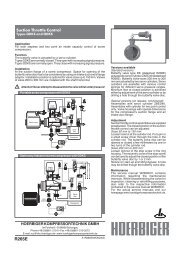
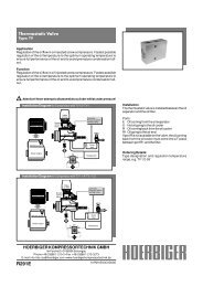
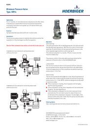
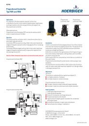
Suction Control Valve<br />
Types HDKG120 and HDKO120<br />
Application<br />
For both stepless or two point capacity control of screw compressors, which<br />
can be pressurized with their full discharge pressure at shut - down.<br />
Operation<br />
Straight throughflow valve with butterfly type control disc and swing type <strong>nonreturn</strong><br />
valve.<br />
Operation of the swing type non-return valve<br />
The suction line is closed quickly, automatically, and independently of any<br />
other components of the compressor if the air flow is interrupted or reversed.<br />
Operation of the butterfly type control disc<br />
Both stepless and two point control via the attached servo cylinder type<br />
ZAED40.<br />
Type HDKG120:<br />
Normally closed. Signal pressure opens the control disc.<br />
Type HDKO120:<br />
Normally open. Signal pressure closes the control disc.<br />
! Attention! Never attempt to disassamble a cylinder whilst under pressure!<br />
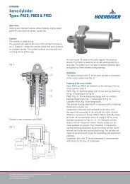
Portable compressor, HDKG 120<br />
Injection pump<br />
Stationary compressor, HDKG 120<br />
Electric motor<br />
Diesel engine<br />
Z<br />
HDKG<br />
HDKG<br />
Intake<br />
air filter<br />
Air end<br />
Intake<br />
air filter<br />
Air end<br />
HOERBIGER KOMPRESSORTECHNIK GMBH<br />
Im Forchet 5 • D-86956 Schongau<br />
Phone +49 (0)8861- 210-0 • Fax +49 (0)8861- 210-3273<br />
E-mail: info-hks-rcc@hoerbiger.com • www.hoerbigerkompressortechnik.de<br />
R234E<br />
P(N)<br />
TV<br />
P(N)<br />
TV<br />
V(NO)<br />
S(NC)<br />
V(NC)<br />
Oil/air<br />
filter<br />
Oilseparator<br />
Oil/air<br />
filter<br />
Oilseparator<br />
MPVL<br />
S(NC)<br />
PMAX<br />
MPVL<br />
AVP<br />
DS<br />
A1R234E03DAC00D<br />
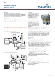
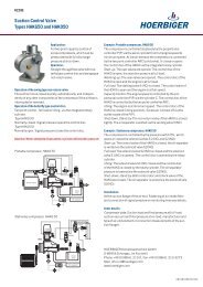
Examples<br />
Portable compressor, HDKG120<br />
The compressor is controlled steplessly from full<br />
load to zero load by the proportional controller P(N):<br />
Start-up: The control disc of the HDKG is closed<br />
(idling position).<br />
Warming-up: The starting valve S (NC) is closed.<br />
The control disc of the HDKG is closed and the<br />
engine is warming up at minimum speed.<br />
Full load: The starting valve S (NC) is open. The<br />
control disc of the HDKG is open and the engine is at<br />
full speed.<br />
Capacity control: Both the control disc of the HDKG<br />
and the injection pump of the engine are steplessly<br />
controlled by the proportional controller P (N).<br />
Idling: The control disc of the HDKG is in idling<br />
position and the engine is at minimum speed.<br />
Compressor at full pressure excess air is blown off<br />
via the bleed valve AVP.<br />
Shut down: The check valve of the HDKG is closed<br />
tightly. The oil separator is vented via the venting<br />
valve V(VC).<br />
Stationary compressor, HDKG120<br />
The proportional controller controls the capacity of<br />
the compressor steplessly, if there is a large air<br />
requirement. The electric pressure switch (DS) turn<br />
the compressor into idling if less air is required.<br />
Start-up: S(NC) is closed, the control disc of the<br />
HDKG is closed, the oil separator is vented via<br />
venting valve V(NO).<br />
Full load: The solenoid valve S(NC) is opened. The<br />
venting valve V(NO) is closed and the control disc of<br />
the HDKG is opened by the servo cylinder.<br />
Capacity control: Between full load and approx. 70%<br />
load. The control disc of the HDKG is partially closed<br />
by an infinitely variable signal from the proportional<br />
controller P(N). At less air requriement DS switchs<br />
the compressor into idling.<br />
Idling: The solenoid valve S(NC) is closed. The<br />
control disc of the HDKG is closed by the servo<br />
cylinder. The oil separator pressure is lowered via<br />
the venting valve V(NO).<br />
Shut-down, stand-by: Both control disc and check<br />
flap of the HDKG are closed. The oil separator is<br />
vented via the venting valve V(NO).<br />
Installation<br />
At the suction flange of the air end, either directly or<br />
via flange adaptor, depending on the type of air end.<br />
For fastening of air intake filter and connection of<br />
signal pressure or monitoring lines see details.<br />
Order details<br />
Compressor data: Suction load and final pressure at<br />
full load, suction vacuum and final pressure<br />
at no-load, manufacturer and type of air<br />
end element or connection<br />
measurements of the suction flanges.<br />
Wanted controller action: A, B or C.
Details<br />
Nominal diameter DN mm 120<br />
Type HDKG120 for start-up with suction control valve closed<br />
HDKO120 for start-up with suction control valve open<br />
Max. working pressure PS bar (g) 16<br />
Temperature range °C - 20 to +90 • in case of an emergency stop: up to 140<br />
Control characteristic<br />
from closed position to 45° opening angle approximately logarithmic<br />
K VA<br />
-value m 3 /h 440 • for air intake from free atmosphere<br />
Air intake capacity m 3 /min Pressure drop at fully opened control valve and proposed range of application see diagram<br />
Idling capacity d=12 mm standard nozzle diameter for start-up and zero load bypass system 1)<br />
Dimensions mm see installation drawing<br />
Connections mm Compressor, suction flange: F = bolt holes (number, diameter, pitch circle dia.<br />
suitable for air end type specified in order)<br />
Signal pressure inlet: E = G 1/8<br />
Additional connections: G, K = G 1/2<br />
U, W = G 1/4<br />
Installation attitude with air intake connection (hose coupling) facing upwards (± 30°)<br />
Servo cylinder<br />
ZAED40 for stepless control or two point control of the butterfly type control valve<br />
Springs for different characteristics available<br />
Control signal bar (g) Equivalent spring, maximum pressure: 7 for two point control<br />
10 for stepless control (100 to 0%)<br />
Medium see datasheet R266<br />
Medium oily pressurized air, filtered • recommended compressed air quality according to DIN ISO 8573-1, class 5<br />
Reference oil: see www.hoerbigerkompressortechnik.de<br />
Materials<br />
Weight kg 12,8<br />
Housing parts: Aluminium alloy<br />
Internal parts: Aluminium alloy, corrosion resistant steel, plated steel<br />
PTFE-compound bearings, Viton sealings, Perbunane diaphragm<br />
1)<br />
Manufacturers of air ends sometimes propose an optimum suction vacuum for zero load conditions. Please specify both<br />
required suction vacuum and full load capacity or required bypass nozzle diameter.<br />
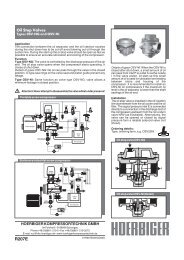
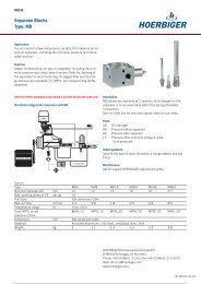
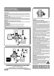
Pressure drop in dependance of air intake (F.A.D.)<br />
Dimensions (mm)<br />
0.03<br />
0.02<br />
ø150<br />
Pressure drop within the<br />
suction control valve ∆p A<br />
[bar (g)]<br />
0.01<br />
0.006<br />
0.004<br />
0.002<br />
6 7 8 10 12 14 16 20 24 30 40<br />
Intake air quantity at full load V N[m 3 /min]<br />
types HDKG120 and HDKO120<br />
types HDKG85 and HDKO85<br />
types HDKG160 and HDKO160<br />
Recommended application:<br />
Range A: Portable compressors with stepless capacity<br />
control from full load to idling<br />
Range B: Stationary compressors with stepless control<br />
from full load to minimum(approx. 70 %),<br />
two point control at low air demand.<br />
Range C: Two point control, either full load or idling<br />
C<br />
B<br />
A<br />
308<br />
240<br />
100<br />
30<br />
50<br />
K<br />
W<br />
ø145<br />
ø260<br />
300<br />
100<br />
84.5 84.5<br />
U<br />
G<br />
E<br />
78<br />
100<br />
240<br />
d (bypass nozzle)<br />
The diagram shows the pressure drop ∆p A<br />
within the suction control valve<br />
at full load, including the pressure loss caused by accelerating ambient air<br />
to intake velocity.<br />
Pressure drops caused by intake air filters and adjacent air lines are not<br />
included, since they are dependent on designs selected by the compressor<br />
manufacturer.<br />
302<br />
147 75<br />
15<br />
W<br />
K<br />
U<br />
G<br />
75<br />
15<br />
80<br />
E<br />
Maintenance<br />
The service manual W232RCC contains information<br />
169<br />
regarding the maintenance intervals. While disassembling the<br />
F<br />
valve for inspection, cleaning or retrofitting purposes, also<br />
refer to the respective information contained in the service<br />
manual W232RCC. For the actual service manuals visit our<br />
homepage www.hoerbigerkompressortechnik.de.<br />
HOERBIGER can not grant any warranty for the correctness of technical or other datas in catalogues, brochures and other printed material. HOERBIGER reserves the<br />
right to alter its products without notice. This also applies to products already on order provided that such alternations can be made without subsequential changes being<br />
necessary in specifications already agreed.