Cable Festoon Insul-8 Festoon Systems
CAT1005.0 Festoon Systems.indd - Palau.com.mx
CAT1005.0 Festoon Systems.indd - Palau.com.mx
- No tags were found...

You also want an ePaper? Increase the reach of your titles
YUMPU automatically turns print PDFs into web optimized ePapers that Google loves.
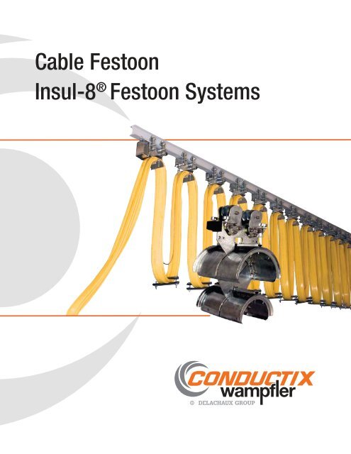
<strong>Cable</strong> <strong>Festoon</strong><br />
<strong>Insul</strong>-8 ® <strong>Festoon</strong> <strong>Systems</strong>
Contents<br />
<strong>Cable</strong> <strong>Festoon</strong> <strong>Systems</strong> Overview 3<br />
Quick Quote Software 4<br />
Push Button Pendants 5<br />
<strong>Festoon</strong> Specification Data Sheets 6-7<br />
CMAA Crane Classifications and NEMA Ratings 8<br />
Flat <strong>Cable</strong> and Connectors 9-11<br />
<strong>Cable</strong> Connectors - For Flat <strong>Cable</strong> 9<br />
PVC Flat <strong>Cable</strong> 10<br />
Neoprene Flat <strong>Cable</strong> & Glands 11<br />
Stretch Wire <strong>Systems</strong> 12-13<br />
C-Track <strong>Systems</strong> - 40 to 80 lb per trolley, 250 fpm 14-23<br />
Standard Duty C-Track 14-19 Heavy Duty C-Track 20-23<br />
Square Bar <strong>Systems</strong> - 45 to 150 lb per trolley, 250 fpm, Dusty Environments 24-28<br />
Standard Duty Square Bar 24-25 Heavy Duty Square Bar 26-28<br />
Medium-Duty I-Beam <strong>Systems</strong> - 55 to 175 lb per trolley, 200 to 350 fpm<br />
Series 200 for Flat <strong>Cable</strong> 29 Series 225 for Flat <strong>Cable</strong> 30-31<br />
Series 250 for Flat <strong>Cable</strong> 32 Series 250 for Round <strong>Cable</strong> 33<br />
Series 250 Running Gear 34<br />
Series 350 for Flat <strong>Cable</strong> 35 Series 350 for Round <strong>Cable</strong> 36<br />
Series 350 Running Gear 37<br />
Tow <strong>Cable</strong> and Tow Webbing 38 Flat and Round <strong>Cable</strong> Organizers 39<br />
Quick Disconnect Pin Connectors 40 Junction Boxes 41<br />
Heavy-Duty I-Beam <strong>Systems</strong> - 315 to 1100 lb per trolley, up to 500 fpm 42-64<br />
System Overview 42 Ordering Steps 43<br />
Terms and Definitions 44-45 <strong>Cable</strong> Arrangement 46<br />
Trolley Selection 47 Main Roller Selection 48<br />
System Calculations 49 450 Series Trolley Features 50<br />
450 Series Trolleys 51-53 Auxiliary Saddles 54<br />
Bumper Extensions 55 S-Beam Running Gear 56-57<br />
W-Beam Running Gear 58-59 Tow Rope 60<br />
Tow Chain 61 Shock Cords 62-63<br />
Round <strong>Cable</strong> Organizers 64 <strong>Cable</strong> Separators 64<br />
(blank) 65<br />
Terms, Conditions, and Warranty 66<br />
Other Products by Conductix-Wampfler 67<br />
Conductix-Wampfler Americas - Contact Information 68<br />
2<br />
Visit www.conductix.com for the most current information.
<strong>Cable</strong> <strong>Festoon</strong> <strong>Systems</strong><br />
Conductix-Wampfler offers a comprehensive range<br />
of <strong>Cable</strong> <strong>Festoon</strong> <strong>Systems</strong> to support, protect,<br />
and manage power/data cables or air/fluid hoses.<br />
Regardless of the particular cable or hose package,<br />
the running speed, indoors or out, Conductix-<br />
Wampfler has the appropriate system for the job.<br />
<strong>Cable</strong> <strong>Festoon</strong> <strong>Systems</strong> are particularly suitable for<br />
demanding environments, such as in mills and at port<br />
facilities. Our systems are ideal for overhead cranes,<br />
gantry cranes, water treatment systems, car wash<br />
systems, bulk material conveyors, plating lines, and<br />
many other types of moving equipment.<br />
You can choose from a complete array of cable and<br />
festoon hardware, and accessories such as cable<br />
connectors, tow cable, tow webbing, cable organizers,<br />
junction boxes, and Push Button Pendants - Refer to<br />
Catalog CAT1001.<br />
Conductix-Wampfler specializes in customengineering<br />
systems. If you don’t see exactly what you<br />
need, contact us with your requirements.<br />
Conductix-Wampfler operates according to stringent<br />
quality systems to assure that you will get the right<br />
product every time. Our plants in the United States,<br />
Germany, France, and Italy are ISO 9001:2000<br />
certified.<br />
Conductix-Wampfler is the world leader in the design<br />
and manufacture of high-performance cable festoon<br />
systems for industrial applications. In the USA our<br />
company represents the <strong>Insul</strong>-8, Industrial Electric<br />
Reels (IER), Wampfler, and Howell Corporation product<br />
brands.<br />
Stretch Wire and<br />
C-Track<br />
Well suited for light duty<br />
applications. Economical and<br />
dependable for small to medium<br />
cranes and moving hoists.<br />
C-track systems can be<br />
ordered pre-assembled by our<br />
experienced personnel under<br />
ideal factory conditions saving<br />
time and money on the job site!<br />
Square Bar<br />
<strong>Festoon</strong> systems that<br />
run on square bars are<br />
particularly suited for very<br />
dusty environments. The<br />
bar, oriented in a diamond<br />
configuration, does not collect<br />
dust.<br />
Medium-Duty I-Beam<br />
<strong>Festoon</strong><br />
Medium-duty trolleys run on<br />
various styles and sizes of<br />
I-beams to handle mid-sized<br />
cable packages. Ideal for<br />
mid-sized cranes and material<br />
handling equipment.<br />
Heavy-Duty I-Beam<br />
<strong>Festoon</strong><br />
HD <strong>Festoon</strong>s are robust systems<br />
to handle large cable packages.<br />
Designed for port container<br />
cranes, process cranes, and<br />
other large machines. Can<br />
be pre-assembled for easy<br />
installation.<br />
Visit www.conductix.com for the most current information.<br />
3
Conductix-Wampfler “Quick Quote” Software<br />
If you configure or purchase conductor bar systems, festoon systems, push<br />
button pendants, radio controls, and/or cable reels on a regular basis,<br />
you need a copy of our innovative Quick Quote software! This advanced<br />
program automatically configures complete systems. It generates bills of<br />
materials, quotations, and system schematics. You can also load your customers<br />
into the program and send quotes automatically. You can turn your<br />
quote into an order with a click! Here is just a partial list of Quick Quote’s<br />
advanced features:<br />
Conductor Bar <strong>Systems</strong>:<br />
• Calculates crane amp draw with multiple vehicles<br />
• Automatically calculates and graphs voltage drop given single<br />
or multiple power feed locations<br />
• Handles advanced bar and collector mounting configurations<br />
• Provides conductor bar system schematic<br />
<strong>Festoon</strong> <strong>Systems</strong>:<br />
• Handles most common festoon mounting configurations<br />
• Allows set-up cable package arrangements and clamp<br />
configurations<br />
• Handles festoon pre-wiring and pre-assembly options<br />
Pendants & Radios:<br />
• Handles custom pendant configurations<br />
• Handles custom radio applications and kits<br />
Quick Quote is supplied on our CD ROM “All Catalogs and Quick Quote”,<br />
which can be ordered on www.conductix.us from the Catalogs section. The<br />
program requires an access code which can be obtained from Conductix-<br />
Wampfler.<br />
Contact Conductix-Wampfler Sales today at 1-800-521-4888 or e-mail us<br />
at info.us@conductix.com for more information.<br />
4<br />
Visit www.conductix.com for the most current information.
Push Button Pendants<br />
A great complement to your festoon systems is a high<br />
quality Conductix-Wampfler Push Button Pendant.<br />
We have offered ergonomic, economical Push Button<br />
Pendants since the early 1990’s.<br />
We offer dozens of standard push button pendant<br />
configurations to suit the unique needs of demanding<br />
industrial users. These modular units are assembled<br />
from stocked components for quick delivery and are<br />
competitively priced.<br />
The experienced engineering and sales people at<br />
Conductix-Wampfler are experts in the application<br />
of Push Button Pendants to all kinds of industrial<br />
applications.<br />
80 Series<br />
Ergonomic; Accommodates from 2 to 12<br />
buttons. Many configurations. High-impact<br />
NEMA 4X case with Neoprene-booted<br />
buttons. 2 and 3 button Pistol Grip versions<br />
available.<br />
UL / cUL Listed<br />
60 Series<br />
Economical; 2 to 4 buttons. Many<br />
configurations available. High-impact NEMA<br />
4 case. A 2-button Pistol Grip version<br />
available.<br />
UL / cUL Listed<br />
For details, please ask for CAT1001 “Push Button<br />
Pendants” or download the PDF from our web site.<br />
Pre-Wiring Option<br />
All pendants can be ordered pre-wired. Contact the<br />
Factory for details!<br />
20 Series<br />
For direct control over small single phase<br />
motors at 120 or 240 volts. Durable NEMA<br />
4 housing.<br />
UL / cUL Listed<br />
Visit www.conductix.com for the most current information.<br />
5
<strong>Festoon</strong> Specification Data Sheet<br />
In order for the <strong>Festoon</strong> System to be designed and perform properly the following <strong>Festoon</strong> Data is required:<br />
Request Date:<br />
Company:<br />
System Parameters (circle units of measure used)<br />
Crane type:<br />
CMAA crane class (Pg. 8)<br />
Travel speed:<br />
ft/min m/min<br />
Acceleration: ft/s 2 m/s 2<br />
Duty cycle (hr/day):<br />
Type of <strong>Festoon</strong> System(s) Required:<br />
Power Control Power & Control<br />
Sales Person:<br />
Contact:<br />
Title:<br />
Telephone:<br />
Fax:<br />
E-Mail:<br />
Operating Conditions (circle units of measure used)<br />
Enviroment: Indoor Outdoor<br />
Temperature range (F 0 C 0 ) Min Max.<br />
Humidity (%)<br />
Corrosives? (please list)<br />
Hazardous location?<br />
Class, Div., Group:<br />
System Dimensions<br />
Allowable Storage Distance (SD)<br />
Total Track Length (TL)<br />
(or “span” of the crane)<br />
Active Travel (AT)<br />
System Window<br />
(width)<br />
Fixed End Pigtail<br />
Mobile End Pigtail<br />
Allowable Loop Depth (LD)<br />
System Dimensions - Refer to dwg above (circle units of measure used):<br />
TL: ft m System Window: in. mm<br />
AT: ft m Fixed end pigtail: ft m<br />
LD: ft m Mobile end pigtail: ft m<br />
SD: ft m I-beam size (if req’d)*:<br />
* Or fill out beam dimensions on Pg. 7.<br />
Type of “Lead” Trolley Req’d: Tow trolley Tow clamp Control Trolley<br />
6<br />
Visit www.conductix.com for the most current information.
<strong>Festoon</strong> Specification Data Sheet<br />
<strong>Festoon</strong> <strong>Cable</strong> Requirement<br />
<strong>Cable</strong> Specification: Flat Round <strong>Cable</strong> Jacket: Neoprene PVC<br />
Item Qty <strong>Cable</strong> Type/Description AWG # Cond Dimensions (in) Wt (lb/ft)<br />
1<br />
2<br />
3<br />
4<br />
5<br />
6<br />
7<br />
8<br />
Accessories / Options Required<br />
Factory Pre-assembly: yes no Electrical J-Boxes: yes no<br />
<strong>Cable</strong> Cord Grips: yes no Factory Pre-wiring<br />
(Check one or both):<br />
Electrical J-Box NEMA Rating:<br />
Fixed<br />
End<br />
Mobile<br />
End<br />
Control Trolley ( if required): No-J-box J-box Quick disconnect<br />
List I-Beam Dimensions - if applicable and if beam type/size not known<br />
US<br />
European<br />
S - Type Beam<br />
W - Type Beam<br />
A<br />
B<br />
Angled Running<br />
Surface<br />
W<br />
X<br />
Flat Running<br />
Surface<br />
Z<br />
C<br />
Y<br />
List Beam Dimensions<br />
(if beam type / size is not known)<br />
A<br />
B<br />
C<br />
W<br />
X<br />
Y<br />
Z<br />
Note: Please attach any other information that might help specify the<br />
correct festoon system. See Pg.15 for details on how festoons<br />
are typically mounted to overhead cranes.<br />
Phone: 800 521 4888 | 402 339 9300<br />
Fax: 800 780 8329 | 402 339 9627<br />
Visit www.conductix.com for the most current information.<br />
7
CMAA Crane Classifications and NEMA Ratings<br />
CMAA Crane Classifications<br />
Provided for general information only. Refer to CMAA Section 78-6 for full definitions.<br />
Class A (Standby or Infrequent Service): Performs precise lifts at slow speed, with long idle period between lifts. Performs lifts at full or near<br />
rated capacity. Power houses, public utilities, turbine rooms.<br />
Class B (Light Service): Light service requirements at slow speed. Performs 2 to 5 lifts/hour, light to occasional full loads, at 10 feet average<br />
height. Repair shops, light assembly, service buildings, light warehousing.<br />
Class C (Moderate Service): Moderate service requirement with loads averaging 50% of capacity. 5 to 10 lifts per hour at 15 feet average lift<br />
height. Not more that 50% of lifts at rated capacity. Machine shops, paper mill machine rooms, etc.<br />
Class D (Heavy Service): Bucket/magnet duty, where heavy duty production is required. Loads of 50% capacity handled constantly. 10 to 20<br />
lifts per hour averaging 15 feet lift height. Not over 65% of the lifts at rated capacity. Heavy machine shops, foundries, fabricating plants, steel<br />
warehouses, container yards, lumber mills, etc.<br />
Class E (Severe Service): Loads approaching capacity throughout the life of the crane. 20 or more lifts per hour at or near rated capacity.<br />
Magnet/bucket cranes for scrap yards, cement mills, lumber mills, fertilizer plants, container handling.<br />
Class F (Continuous Severe Service): Handles loads approaching capacity continuously under severe service conditions throughout the life of<br />
the crane. Includes custom designed specialty cranes performing work critical to the total production facility. Needs to have the highest reliability<br />
and ease of maintenance.<br />
NEMA Enclosure Ratings<br />
Provided for general information only. Refer to NEMA Standard 250 and IP AS 1939-1986 for full definitions.<br />
Note: All enclosures types provide a degree of protection to personnel against incidental contact with the enclosed equipment.<br />
NEMA 1 (IP10): Enclosures constructed for indoor use to provide a degree of protection against falling dirt<br />
NEMA 2 (IP11): Enclosures constructed for indoor use to provide a degree of protection against falling dirt, and to provide a degree of protection<br />
against dripping and light splashing of liquids<br />
NEMA 3 (IP54): Enclosures constructed for either indoor or outdoor use to provide a degree of protection against falling dirt, rain, sleet, snow,<br />
and windblown dust; and that will be undamaged by external formation of ice on the enclosure<br />
NEMA 3R (IP14): Enclosures constructed for either indoor or outdoor use to provide a degree of protection against falling dirt, rain, sleet, and<br />
snow; and that will be undamaged by external formation of ice on the enclosure. (Enclosure can be vented.)<br />
NEMA 4 (IP56): Enclosures constructed for either indoor or outdoor use to provide a degree of protection against falling dirt, rain, sleet, snow,<br />
windblown dust, splashing water, and hose-directed water, and that will be undamaged by the external formation of ice on the enclosure<br />
NEMA 4X (IP56): Enclosures constructed for either indoor or outdoor use to provide a degree of protection against falling dirt, rain, sleet, snow,<br />
windblown dust, splashing water, hose-directed water, and corrosion and that will be undamaged by thee external formation of ice on the<br />
enclosure<br />
NEMA 6 (IP67): Enclosures constructed for either indoor or outdoor use to provide a degree of protection against damage by the external<br />
formation of ice on the enclosure.<br />
NEMA 12 (IP52): Enclosures constructed (without knockouts) for indoor use to provide a degree of protection against falling dirt; against<br />
circulating dust, lint, fibers, and flying debris and against dripping and light splashing of liquids.<br />
NEMA 13 (IP54): Enclosures constructed for indoor use to provide a degree of protection against falling dirt, circulating dust, lint, fibers, and<br />
flying debris and against the spraying, splashing, and seepage of water, oil, and non-corrosive coolants.<br />
For information on hazardous location specifications, please contact the factory.<br />
8<br />
Visit www.conductix.com for the most current information.
<strong>Cable</strong> Connectors - For Flat PVC <strong>Cable</strong><br />
Constructed with an aluminum body and rubber bushing. For termination of cable at power source or<br />
junction box. “For <strong>Cable</strong>” reference numbers, see Pg. 10.<br />
As noted below, some connectors can accommodate two different cables.<br />
No. of<br />
<strong>Cable</strong>s<br />
<strong>Cable</strong> Size<br />
AWG<br />
No. of<br />
Cond.<br />
For <strong>Cable</strong><br />
#<br />
No. of<br />
Cond.<br />
Second <strong>Cable</strong> Size<br />
AWG<br />
Ref <strong>Cable</strong><br />
#<br />
Connector<br />
Part No.<br />
NPT<br />
in. (mm)<br />
1 4 4 26550Y - - - 35838 2.0 (51)<br />
1 6 4 21814Y - - - 35838B 2.0 (51)<br />
1 8 4 26698Y - - - 35837 1.5 (38)<br />
1 10 4 22542Y - - - 35835C 1.0 (25)<br />
1 12 4 22994Y - - - 35835B 1.0 (25)<br />
1 14 4 21815Y - - - 35835 1.0 (25)<br />
1 12 8 26005Y - - - 35837B 1.5 (38)<br />
2 12 8 26005Y - - - 35838G 2.0 (51)<br />
1 14 8 26110Y - - - 35837C 1.5 (38)<br />
2 14 8 26110Y - - - 35837E 1.5 (38)<br />
1 16 8 22607Y - - - 35837D 1.5 (38)<br />
2 16 8 22607Y - - - 35837F 1.5 (38)<br />
1 14 12 21813Y - - - 35838C 2.0 (51)<br />
2 14 12 21813Y - - - 35838E 2.0 (51)<br />
1 16 12 23324Y - - - 35838D 2.0 (51)<br />
2 16 12 23324Y - - - 35838F 2.0 51)<br />
1 16 8 22607Y 4 14 21815Y 35837G 1.5 (38)<br />
1 14 8 26110Y 4 14 22542Y 35837H 1.5 (38)<br />
1 16 8 22607Y 4 10 22542Y 35837J 1.5 (38)<br />
1 14 8 26110Y 4 10 21815Y 35837K 1.5 (38)<br />
1 14 12 21813Y 4 10 22542Y 35838H 2.0 (51)<br />
2 16 8 22607Y 4 12 22994Y 35837L 1.5 (38)<br />
2 14 8 26110Y 4 12 22994Y 35837M 1.5 (38)<br />
Heat Shrinkable Connectors<br />
For Flat or Round <strong>Cable</strong><br />
Dim “A:<br />
For single cable and multiple cable groups. These are corrosion resistant and flame retardant. They<br />
exceed US Navy requirements for tightness and integrity when used with one flat cable or multiple flat<br />
cables on the same size.<br />
<strong>Cable</strong> Opening<br />
in. (mm)<br />
Knockout Dia.<br />
in. (mm)<br />
Part No.<br />
Dimension<br />
“A”<br />
Wt lb (kg)<br />
1.60 (41) 2.00 (51) 03147 6.17 (157) 0.40 (0.18)<br />
1.10 (28) 1.37 35) 03146 4.50 (114) 0.10 (0.05)<br />
0.75 (19) 1.00 (25) 03145 4.09 (104) 0.06 (0.03)<br />
Visit www.conductix.com for the most current information.<br />
9
PVC Flat <strong>Cable</strong><br />
PVC flat cable has a yellow jacket. A black jacket option is available by request<br />
- contact the Factory. All cables from 16 awg to 10 awg have rip cords for easy<br />
removal of outside jacket.<br />
To calculate required cable length. Take the track length and add 10%. Then add<br />
the length you require for end connections.<br />
<strong>Cable</strong> Size<br />
No. of<br />
Part No. Continuous<br />
Amp<br />
Rating*<br />
Cond<br />
Short Time<br />
Rating Amps**<br />
Strands per<br />
Conductor<br />
Unshielded<br />
<strong>Cable</strong> Dim.<br />
Nom in. (mm) +<br />
AWG PVC Jacket Shielded 60 min 30 min Height Width<br />
Wt ft/lb<br />
(kg/m)<br />
4 2 23958Y 120 148 173 665 0.56 (14) 1.96 (50) 1.27 (.60)<br />
4 4 26550Y 90 111 130 420 0.49 (12) 1.70 (43) .75 (.34)<br />
4 6 21814Y 70 83 94 266 0.44 (11) 1.45 (37) .60 (.27)<br />
4 8 26698Y 50 63 69 168 0.37 (9) 1.19 (30) .42 (.19)<br />
4 10 22542Y 40 49 52 105 0.27 (7) 0.88 (22) .24 (.11)<br />
4 12 22994Y 30 36 40 65 0.23 (6) 0.75 (18) .16 (.07)<br />
4 14 21815Y 25 31 32 41 0.21 (5) 0.63 (16) .12 (.05)<br />
8 12 26005Y 21 n/a n/a 65 0.23 (6) 1.34 (34) .32 (.15)<br />
8 14 26110Y 17 n/a n/a 41 0.21 (5) 1.18 (30) .22 (.10)<br />
8 16 22607Y 31772+ 15 n/a n/a 65 0.20 (5) 1.11 (28) .18 (.08)<br />
12 14 21813Y 34819+ 17 n/a n/a 41 0.21 (5) 1.90 (48) .34 (.15)<br />
12 16 23324Y 31580+ 15 n/a n/a 65 0.20 (5) 1.61 (41) .27 (.12)<br />
4 16 31734+ n/a n/a n/a 65 0.24 (6) 0.76 (19) .16 (.07)<br />
* Continuous Duty Rating, 30 0 C - See NEC Table 16.14 (A). Ampacity Correction Factors for temperatures above<br />
30 O C (86 O F)<br />
** For crane and hoist motors in accordance with article 610 of the 2008 National Electric Code for 90 O C <strong>Cable</strong>s.<br />
+ Unshielded cable measurements may vary. Contact Conductix-Wampfler for shielded cable dimensions.<br />
10<br />
Visit www.conductix.com for the most current information.
Neoprene Flat <strong>Cable</strong><br />
Neoprene Flat <strong>Cable</strong>s are used for festoon systems on cranes, hoists, and any other equipment with lateral transverse motion. They are suitable<br />
for indoor or outdoor applications where oil resistance and low-temperature flexing are required. The jacket is Neoprene rated at -40 O C to 90 O C<br />
and has a UV inhibitor. The insulation for the awg-size cable is EPR rated at 90 O C. The insulation for the metric-sized cable is Protolon EP.<br />
Color Code:<br />
AWG Sizes<br />
4 conductor cables: green/yellow, black, blue, and brown<br />
8-12 conductors: green/yellow, with all others black with numbers<br />
# of<br />
Cond<br />
AWG<br />
Ampacity<br />
at 45 O C*<br />
Part No.<br />
Strands per<br />
Conductor<br />
Thickness<br />
(in.)<br />
Width<br />
(in.)<br />
Wt lb/ft Wt kg/m<br />
12 16 18 28151 76 0.260 1.787 0.24 0.035<br />
12 14 24 28154 130 0.310 2.137 0.54 0.075<br />
8 14 25 28153 130 0.295 1.500 0.39 0.054<br />
4 14 27 28152 130 0.295 0.790 0.19 0.026<br />
4 12 36 28155 211 0.343 0.976 0.29 0.040<br />
4 10 47 28157 168 0.360 1.051 0.35 0.048<br />
4 8 69 28158 287 0.414 1.252 0.52 0.072<br />
4 6 94 28159 119 0.480 1.528 0.78 0.108<br />
4 4 117 28160 186 0.563 1.799 1.05 0.145<br />
4 2 157 28161 266 0.602 2.063 1.50 0.207<br />
4 2/0 280 100698 333 0.770 2.630 2.60 0.359<br />
Metric Sizes<br />
# of<br />
Cond<br />
mm 2<br />
Ampacity<br />
at 30 O C*<br />
Part No.<br />
Strands per<br />
Conductor<br />
Thickness<br />
(mm)<br />
Width in<br />
(mm)<br />
Wt kg/m<br />
Wt lb/ft<br />
12 1.5 14 103885 77 6.0 42.0 0.510 0.342<br />
4 2.5 32 103888 130 7.0 20.0 0.270 0.181<br />
12 2.5 19 102804 130 7.5 55.0 0.830 0.557<br />
4 4.0 43 103889 210 8.5 24.0 0.400 0.269<br />
4 6.0 56 103890 175 9.0 26.5 0.500 0.335<br />
4 10.0 78 103891 300 10.5 33.0 0.760 0.510<br />
4 16.0 104 103892 480 12.5 38.0 1.100 0.739<br />
4 25.0 138 103893 750 14.0 44.5 1.580 1.061<br />
4 35.0 171 100481 276 16.5 50.5 2.150 1.444<br />
4 50.0 213 103894 396 19.0 59.5 2.960 1.988<br />
4 70.0 263 103895 560 21.0 71.0 4.000 2.687<br />
*These capacities are a general guide to conductor size selections. They are not intended to supersede NEC or ICEA ampacity tables.<br />
<strong>Cable</strong> Connector Assemblies<br />
These connector assemblies include Neoprene glands. Field cut to match the cable or factory cut<br />
before shipment. Call factory for details.<br />
Size Part No. Wt lb (kg)<br />
2.75 x .875 (70 x 22) 26112 1.75 (0.80)<br />
5.25 x 1.75 (133 x 45) 26113 2.00 (0.91)<br />
4.50 x 2.75 (114 x 70) 26114 4.75 (2.15)<br />
Visit www.conductix.com for the most current information.<br />
11
Stretched Wire Rope Kits - For Flat <strong>Cable</strong><br />
SW<br />
2<br />
SW<br />
6<br />
SW<br />
5<br />
SW<br />
4<br />
SW<br />
1<br />
SW<br />
3<br />
SW<br />
15<br />
SW<br />
Stretched Wire Rope <strong>Festoon</strong> Kits for flat cable are suited<br />
for light duty applications where an intermediate support<br />
structure is not available. Economical and dependable,<br />
stretched wire rope systems provide electrification to small<br />
cranes, moving hoists, and jib cranes. The kits below include<br />
standard zinc plated hardware.<br />
Max. Load Per Trolley<br />
Single wheel 10 lb (4.5 kg)<br />
Double wheel 20 lb (9.1 kg)<br />
Max. Running Speed 200 ft/min (60.9 m/min)<br />
14<br />
Max. Span<br />
Dwg ID Component Part No.<br />
Stretch Wire <strong>Festoon</strong> Kits Include Parts Listed Below:<br />
Dwg<br />
ID<br />
Component<br />
Part No.<br />
SW1 Nylon-coated Wire Rope, 1/4” (6mm) Dia. 22950 SW6 Anchor Bracket 22836<br />
SW2 Hardware Kit 23288 SW14 Flat <strong>Cable</strong> Saddle < 3/4” (20mm) wide 22834<br />
SW3 Tow Bar 39618 SW15 Flat <strong>Cable</strong> Saddle 22835<br />
SW4 Tow Trolley (2 wheel) 22828<br />
n/a Trolley (1 wheel) not shown 22825<br />
SW5 Trolley (2 wheel) shown 22826<br />
Kits with Single-Wheel Trolleys<br />
ft (m)<br />
Kit Part No.<br />
Max Flat<br />
<strong>Cable</strong> Width<br />
Max. Load<br />
Per Trolley<br />
lb (kg)<br />
No. of<br />
Trolleys<br />
in Kit<br />
20 (6.1) 24862 0.75 (19) 10 (4.5) 3<br />
40 (12.2) 24863 0.75 (19) 10 (4.5) 6<br />
60 (18.3) 24864 0.75 (19) 10 (4.5) 9<br />
80 (24.4) 24865 0.75 (19) 10 (4.5) 13<br />
100 (30.5) 24866 0.75 (19) 10 (4.5) 17<br />
Kits with Double-Wheel Trolleys<br />
Max. Span<br />
ft (m)<br />
Kit Part No.<br />
Max Flat<br />
<strong>Cable</strong> Width<br />
Max. Load<br />
Per Trolley<br />
lb (kg)<br />
No. of<br />
Trolleys<br />
in Kit<br />
20 (6.1) 24867 1.75 (19) 20 (9.1) 3<br />
40 (12.2) 24868 1.75 (19) 20 (9.1 6<br />
60 (18.3) 24869 1.75 (19) 20 (9.1 9<br />
80 (24.4) 24870 1.75 (19) 20 (9.1 13<br />
100 (30.5) 24871 1.75 (19) 20 (9.1 17<br />
12<br />
Visit www.conductix.com for the most current information.
Stretched Wire Rope Kits - For Round <strong>Cable</strong> or Hose<br />
SW SW<br />
SW SW SW<br />
9<br />
7<br />
2 6 10<br />
SW<br />
1<br />
SW<br />
3<br />
Stretched Wire Rope <strong>Festoon</strong> Kits for round cable or<br />
hose are suited for light duty applications where an<br />
intermediate support structure is not available. Economical<br />
and dependable, stretched wire rope systems provide<br />
electrification to small cranes, moving hoists, and jib<br />
cranes. The kits below include standard zinc plated<br />
hardware.<br />
SW SW SW<br />
11 12 13<br />
Max. Load Per Trolley<br />
Single wheel 10 lb (4.5 kg)<br />
Double wheel 20 lb (9.1 kg)<br />
Max. Running Speed 200 ft/min (60.9 m/min)<br />
Dwg<br />
ID<br />
Component<br />
Stretch Wire <strong>Festoon</strong> Kits Include Parts Listed Below:<br />
Part No.<br />
Dwg<br />
ID<br />
Component<br />
Part No.<br />
SW1 Nylon-coated Wire Rope, 1/4” (6mm) Dia. 22950 SW9 Trolley (2 wheel) shown 22827<br />
SW2 Hardware Kit 23288 SW10 Adapter 25689<br />
SW3 Tow Bar 39618 SW11 <strong>Cable</strong> Clip 3/16” to 3/8” (5 to 10 mm) 22831<br />
SW6 Anchor Bracket 22836 SW12 <strong>Cable</strong> Clip 3/8” to 9/16” (10 to 15 mm) 22832<br />
SW7 Tow Trolley (2 wheel) 22829 SW13 <strong>Cable</strong> Clip 9/16” to 3/4” (15 to 20 mm) 22833<br />
n/a Trolley (1 wheel) not shown 22825<br />
Kits with Single-Wheel Trolleys<br />
Max. Span<br />
ft (m)<br />
Dia. Range<br />
3/16” to 3/8”<br />
(5-10 mm)<br />
Kit Part No.<br />
Dia. Range<br />
3/8” to 9/16”<br />
(5-15mm)<br />
Dia. Range<br />
9/16” to 3/4”<br />
(15-20 mm)<br />
No. of<br />
Trolleys<br />
in Kit<br />
20 (6.1) 24872 24877 24882 3<br />
40 (12.2) 24873 24878 24883 6<br />
60 (18.3) 24874 24879 24884 9<br />
80 (24.4) 24875 24880 24885 13<br />
100 (30.5) 24876 24881 24886 17<br />
Kits with Double-Wheel Trolleys<br />
Max. Span<br />
ft (m)<br />
Dia. Range<br />
3/16” to 3/8”<br />
(5-10 mm)<br />
Kit Part No.<br />
Dia. Range<br />
3/8” to 9/16”<br />
(5-15mm)<br />
Dia. Range<br />
9/16” to 3/4”<br />
(15-20 mm)<br />
No. of<br />
Trolleys<br />
in Kit<br />
20 (6.1) 24887 24892 24897 3<br />
40 (12.2) 24888 24893 24898 6<br />
60 (18.3) 24889 24894 24899 9<br />
80 (24.4) 24890 24895 24900 13<br />
100 (30.5) 24891 24896 24901 17<br />
Visit www.conductix.com for the most current information.<br />
13
C-Track <strong>Festoon</strong> <strong>Systems</strong> - Standard Duty<br />
The specific C-Track <strong>Festoon</strong> components needed for overhead crane systems depend upon how the system is to be mounted. On the next page<br />
are four typical arrangements. For each versions, you will need to determine the types and lengths of cable using the formula “track length + 10%,<br />
plus hook-up lengths”. You will also need to choose the type of control trolley you want - Junction Box or Quick-Disconnect - and whether to use a<br />
push button pendant or radio remote control to operate the crane. For information about these components, see catalogs CAT1002 and CAT1003.<br />
To assist in the information gathering process, see Specification Data Form on Pgs. 6-7.<br />
3<br />
4<br />
5<br />
Max. Load Per Trolley: 40 lb (18.1 kg)<br />
Max. Running Speed: 250 ft/min (76 m/min)<br />
1<br />
2<br />
6<br />
10<br />
8<br />
7<br />
9<br />
11<br />
17<br />
16<br />
Style “B” Mounting is<br />
Shown - see Pg. 15<br />
15 14<br />
12<br />
13<br />
1<br />
2<br />
3<br />
4<br />
5<br />
6<br />
7<br />
8<br />
9<br />
Fixed End Junction Box<br />
Terminal Strips (inside junction box)<br />
<strong>Cable</strong> Connectors<br />
End Clamp<br />
Track Hanger Clamp Assembly<br />
Intermediate Trolley<br />
Cross Arm Support Channels<br />
Beam Clamp (for cross arm support channels)<br />
C-Track Channel<br />
10<br />
11<br />
12<br />
13<br />
14<br />
15<br />
16<br />
17<br />
Control Unit Trolley with Junction Box; or Quick<br />
Disconnect Control Unit Trolley (not shown)<br />
Track Joint Assembly<br />
Pendant <strong>Cable</strong><br />
Push-Button Pendant Station<br />
Tow Arm<br />
Tow Trolley<br />
Flat PVC <strong>Cable</strong><br />
End Stop<br />
14<br />
Visit www.conductix.com for the most current information.
C-Track <strong>Festoon</strong> Mounting Arrangements<br />
A. Box Girder Style Crane - Control and Power <strong>Festoon</strong> on Opposite Sides<br />
# 35705<br />
To quote this layout, we will need the information on Pg. 14, plus:<br />
• Lengths L1 and L2, if Conductix-Wampfler is to supply the cross<br />
beam support channels, attached with welded-on Suspension Support<br />
Brackets, 35705, Pg. 17.<br />
• Max. loop depth D1 from top of C-Track, and D2 from top of C-Track (or<br />
bottom of I-Beam, if I-Beam is used instead of C-Track)<br />
• Beam size (if I-Beam is used for the power festoon)<br />
B. I-Beam Style Crane - Control and Power <strong>Festoon</strong> on Opposite Sides<br />
# 22264<br />
To quote this layout, we will need the information on Pg. 14, plus:<br />
• Length L, if Conductix-Wampfler is to supply the cross beam support<br />
channels, attached with Cross Arm Support Beam Clamps, 22264, see<br />
Pg. 16.<br />
• Max. loop depth D1 from top of C-Track and D2 from top of C-Track (or<br />
bottom of I-Beam, if I-Beam is used instead of C-Track)<br />
• Beam size, if I-Beam is used for the power festoon<br />
• The size and type of the main beam cap, if one is present<br />
C. I-Beam Style Crane - Control and Power <strong>Festoon</strong> on Same Side<br />
# 22264<br />
To quote this layout, we will need the information on Pg. 14 plus:<br />
• Length L, if Conductix-Wampfler is to supply the cross beam support<br />
channels, attached with Cross Arm Support Beam Clamps, 22264, see<br />
Pg. 16.<br />
• Max. loop depth D from top of C-Track<br />
• The size and type of the main beam cap, if one is present<br />
D. I-Beam Style Crane - Control and Power <strong>Festoon</strong> on Same Side, Welded Cross Support<br />
# 35705<br />
To quote this layout, we will need the information on Pg. 14 plus:<br />
• Length L, if Conductix-Wampfler is to supply the cross beam support<br />
channels, attached with welded-on Suspension Support Bracket, 35705,<br />
Pg. 17.<br />
• Max. loop depth D from top of C-Track<br />
Visit www.conductix.com for the most current information.<br />
15
C-Track <strong>Festoon</strong> <strong>Systems</strong> - Standard Duty<br />
Standard C-Track Channel<br />
14 gauge track channel sections are available in either galvanized or stainless steel. Track<br />
can be curved - Contact the Factory<br />
Channel Length, ft (m) Part No. Galvanized Part No. Stainless Wt lb (kg)<br />
5 (1.5) 33690 39996 5 (2.3)<br />
10 (3.0) 22209 27725 10 (4.5)<br />
20 (6.1) 21909 27724 20 (9.1)<br />
Track Joint Assembly<br />
One required for each track section, per run, minus one. For secure attachment and proper<br />
alignment of track sections. Includes four bolts, lock washers, and nuts. Optional Welded<br />
Joint Assembly for joining track section is also available.<br />
Type Part No. Galvanized Part No. Stainless Wt lb (kg)<br />
Bolted 21954 27726 0.75 (0.34)<br />
Welded 31856 32059 0.75 (0.34)<br />
Cross Arm Support Channel<br />
14 gauge galvanized channel. Ordered in 6” (152) increments. 14 gauge stainless steel<br />
channel is part number 51513* . For 12 gauge Cross-Arm Support Channels, see pg. 21.<br />
Length ft (m) Part No. Wt lb (kg)<br />
12 (305) 36679 1.0 (0.45)<br />
18 (457) 36679B 1.5 (0.38)<br />
24 (610) 36679C 2.0 (0.91)<br />
30 (762) 36679D 2.5 (1.13)<br />
Length ft (m) Part No. Wt lb (kg)<br />
36 (914) 36679E 3.0 (1.36)<br />
42 (1067) 36679F 3.5 (1.59)<br />
48 (1219) 36679G 4.0 (1.81)<br />
✱ Alpha character indicated length, as shown above<br />
Cross Arm Support Beam Clamps<br />
Two required for each cross arm support channel. Hardware is galvanized steel. Clamp is<br />
either aluminum or optional zinc-plated steel.<br />
Clamp Material Bolt Size Part No. Wt lb (kg)<br />
Zinc-plated Steel 3/8” x 2” long 50204 0.45 (0.20)<br />
50204<br />
Track Hanger Clamp Assembly<br />
One required for each cross arm support bracket for each track run. 5 foot (1.5m) spacing.<br />
For Mounting to:<br />
Angle iron brackets (with one mounting<br />
hole)<br />
Cross Arm Support Bracket, hardware<br />
included<br />
Cross Arm Support Bracket - This is a<br />
“low profile” track hanger assembly (not<br />
shown)<br />
Part No.<br />
Galvanized<br />
28510<br />
Part No.<br />
Stainless<br />
Wt lb (kg)<br />
28741 0.40 (0.18)<br />
35707 50308 0.51 (0.23)<br />
22005 n/a 0.81 (0.37)<br />
16<br />
Visit www.conductix.com for the most current information.
C-Track <strong>Festoon</strong> <strong>Systems</strong> - Standard Duty<br />
Anchor Clamp<br />
Holds channel in place. One required per track run; includes hardware.<br />
For use with Part No. Galvanized Part No. Stainless Wt lb (kg)<br />
C-channel 28511 28742 0.40 (0.18)<br />
Cross Arm Support<br />
Channel<br />
35706 50307 0.51 (0.23)<br />
End Stop<br />
One required for power system, two required for control systems with control trolley.<br />
Part No. Galvanized Part No. Stainless Wt lb (kg)<br />
23381 27727 0.20 (0.09)<br />
Track Support Bracket<br />
With fasteners to mount to Cross Arm Support.<br />
Part No. Galvanized Part No. Stainless Wt lb (kg)<br />
38653 n/a 0.47 (0.21)<br />
Track Support Bracket<br />
Comes with mounting hardware.<br />
Part No. Galvanized Part No. Stainless Wt lb (kg)<br />
38654 n/a 0.40 (0.18)<br />
Suspension Support Bracket<br />
Weld-on support bracket to mount 12 gauge support arms to customer runway beam or<br />
cross-bridge beam or girder. See illustrations A and D on Pg. 15.<br />
Part No. Galvanized Part No. Stainless Wt lb (kg)<br />
35705 n/a 1.93 (0.88)<br />
Visit www.conductix.com for the most current information.<br />
17
C-Track <strong>Festoon</strong> <strong>Systems</strong> - Standard Duty<br />
Max. Load Per Trolley: 40 lb (18.1 kg)<br />
Max. Running Speed: 250 ft/min (76 m/min)<br />
Tow Trolley<br />
One Tow Trolley is required for each track run. Tow Trolley is designed for flat cable and has<br />
a cutout in the body to accommodate the Tow Bar. Trolleys are available for round cable or<br />
hose trolleys, contact the factory. Stainless steel version has stainless steel body, saddle,<br />
stainless steel sealed wheels and hardware.<br />
Spark-resistant trolleys designs are available for hazardous locations - Contact the factory.<br />
Style Saddle Dia in. (mm) Part No. Wt lb (kg)<br />
Plated Steel 2.75 (70) 22168 1.12 (0.51)<br />
Stainless Steel 2.75 (70) 39274 1.12 (0.51)<br />
Plastic body<br />
and saddle<br />
2.00 (51) 28614 0.70 (0.32)<br />
Tow Bar<br />
One required for each Tow Trolley. Tow Bar mounts on moving equipment.<br />
Style Length in. (mm) Part No. Wt lb (kg)<br />
Plated Steel 16.0 (406) 39618 1.20 (.54)<br />
Stainless Steel 16.0 (406) 50142 1.20 (.54)<br />
<strong>Cable</strong> Trolleys<br />
5.0” Wide Trolley<br />
Four-wheel cable trolleys with shielded ball bearings are designed to hold flat cables. Used<br />
for cable loops between the Tow Trolley and the End Clamp. Stainless steel version has<br />
stainless steel body, saddle, sealed wheels, and hardware. Trolleys are also available to<br />
handle round cable or hose, contact the factory.<br />
Spark-resistant trolleys designs are available for hazardous locations - Contact the factory.<br />
Saddle Width<br />
in. (mm)<br />
Type Saddle Dia Part No. Wt lb (kg)<br />
5.0 (127) Plated Steel 2.75 (70) 21941 1.00 (0.45)<br />
5.0 (127) Stainless Steel 2.75 (70) 39275 1.00 (0.45)<br />
3.0 (76) Plated Steel 2.75 (70) 21991 0.70 (0.32)<br />
3.0 (76) Stainless Steel 2.75 (70) 39227 0.70 (0.32)<br />
3.0 (76) Plastic body and Saddle 2.00 (51) 28615 0.40 (0.18)<br />
3.0” Wide Trolley<br />
18<br />
Visit www.conductix.com for the most current information.
C-Track <strong>Festoon</strong> <strong>Systems</strong> - Standard Duty<br />
End Clamp<br />
One End Clamp is required for each track run at storage end of track.<br />
Includes clamp and hardware to secure the cable<br />
Type Saddle Dia in. (mm) Part No. Wt lb (kg)<br />
Plated Steel 2.75 (70) 21957 0.56 (0.25)<br />
Stainless Steel 2.75 (70) 39226 0.56 (0.25)<br />
Plastic body<br />
and Saddle<br />
2.00 (70) 28616 0.42 (0.19)<br />
Control Unit Trolley for J-Box<br />
The Control Unit Trolley is designed to hold a control junction box. The<br />
unit has two trolleys and one steel flat cable saddle mounted on a<br />
bracket. Includes fittings to attach junction box to bracket. Junction box<br />
is not included - Order separately from Pg. 41. Stainless steel version<br />
has stainless steel body and saddle, with stainless steel sealed wheels<br />
and hardware.<br />
For hazardous locations, trolleys with spark-resistant bronze rollers are<br />
available, contact the factory.<br />
Style Saddle Dia in. (mm) Part No. Wt lb (kg)<br />
Plated Steel 2.75 (70) 22203B 2.75 (1.25)<br />
Stainless Steel 2.75 (70) 32166 3.00 (1.36)<br />
Control Unit Trolley with Quick Disconnect<br />
Similar to the Control Unit Trolley above, except includes Quick<br />
Disconnect connector set to accommodate a push-button pendant<br />
attached to drop cable. Flat festoon cable is wired into the upper half of<br />
the connector and the pendant drop-cable is wired into the lower half.<br />
See Pg. 40 for more information.<br />
Trolley and hardware are zinc plated.<br />
For hazardous locations, trolleys with spark-resistant bronze rollers are<br />
available, contact the factory.<br />
Connector Electrical Rating: 16A maximum, 600 VAC<br />
Shown with Push Button<br />
Pendant and Pendant <strong>Cable</strong><br />
(purchased separately)<br />
Close-up of Pin Connector Set<br />
No. of<br />
Connector Pins<br />
Saddle Dia in. (mm) Part No. Wt lb (kg)<br />
16 2.75 (70) 2366 5.28 (2.39)<br />
24 2.75 (70 ) 2367 5.59 (2.54)<br />
Note that Conductix-Wampfler offers many styles of pin connectors and junction box<br />
configurations to suit your individual needs - Contact our Sales Department.<br />
For Junction Boxes and Terminal Strips, See Pg. 41<br />
Visit www.conductix.com for the most current information.<br />
19
C-Track <strong>Systems</strong> - Heavy Duty<br />
Shown below is a typical Heavy Duty C-Track <strong>Festoon</strong> <strong>Systems</strong> - Power and Control - for an overhead crane installation. This is a “Type B” (top<br />
of I-Beam) mounting configuration - See page 15. Heavy Duty C-Track is similar to Standard Duty C-Track, as described on Pg. 14, except<br />
that the track is 12 gauge and the hardware is designed to fit the thicker walled channel. Heavy Duty C-Track handles heavier loads and faster<br />
speeds.<br />
3<br />
4<br />
5<br />
Max. Load Per Trolley: 80 lb (36.29 kg)<br />
Max. Running Speed: 500 ft/min (152.4 m/min)<br />
1<br />
2<br />
10<br />
6<br />
8<br />
7<br />
9<br />
11<br />
17<br />
16<br />
Style “B” Mounting is<br />
Shown - see Pg. 15<br />
15 14<br />
12<br />
13<br />
1<br />
2<br />
3<br />
4<br />
5<br />
6<br />
7<br />
8<br />
9<br />
Fixed End Junction Box<br />
Terminal Strips (inside junction box)<br />
Flat <strong>Cable</strong> Connector<br />
End Clamp<br />
Track Hanger Clamp Assembly<br />
<strong>Cable</strong> Trolley<br />
Cross Arm Support Channels<br />
Beam Clamp (for Cross Arm Support Channels)<br />
C-Track Channel<br />
10<br />
11<br />
12<br />
13<br />
14<br />
15<br />
16<br />
17<br />
Control Unit Trolley with Junction Box or Quick<br />
Disconnect Standard Control Unit Trolley (not shown)<br />
Track Joint Assembly<br />
Pendant <strong>Cable</strong><br />
Push Button Pendant<br />
Tow Arm<br />
Tow Trolley<br />
Flat PVC <strong>Cable</strong><br />
End Stop<br />
20<br />
Visit www.conductix.com for the most current information.
C-Track <strong>Systems</strong> - Heavy Duty<br />
Heavy Duty C-Track Channel<br />
12 gauge track channel sections are available in galvanized steel only. Curved track not<br />
available.<br />
Channel Length, ft (m) Part No. Wt lb (kg)<br />
5 (1.5) 22302J 10.0 (4.54)<br />
10 (3.0) 22210 20.0 (9.07)<br />
20 (6.1) 21805 40.0 (10.14)<br />
Cross-arm Support Channel<br />
12 gauge galvanized steel channel is ordered in 6” (152mm) increments. See Pg. 16 for<br />
cross-arm support beam clamps.<br />
Length ft (m) Part No. Wt lb (kg)<br />
Length ft (m) Part No. Wt lb (kg)<br />
36 (914) 36678E 6.0 (2.72)<br />
12 (305) 36678 2.0 (0.91)<br />
42 (1067) 36678F 7.0 (3.18)<br />
18 (457) 36678B 3.0 (1.36)<br />
48 (1219) 36678G 8.0 (3.63)<br />
24 (610) 36678C 4.0 (1.81)<br />
30 (762) 36678D 5.0 (2.27)<br />
Track Joint Assembly<br />
Track Joint Assembly securely attaches and properly aligns track sections. Includes four<br />
bolts, lock washers, and nuts. One required for each track section, per run, minus<br />
one.<br />
Type Part No. Wt lb (kg)<br />
Bolted 21806 1.08 (0.49)<br />
Track Hanger Clamp Assembly<br />
One required at each angle-iron bracket (with one hole) or Cross Arm Support; maximum<br />
10’ spacing. Galvanized finish.<br />
For Mounting to: Part No. Wt lb (kg)<br />
Angle iron brackets (with one mounting hole) 28512 0.45 (0.21)<br />
Cross Arm Support Bracket, hardware included 37465 0.51 (0.23<br />
Anchor Clamp<br />
One required per track run. Includes set-bolt to hold the track in place.<br />
Galvanized finish.<br />
Type Part No. Wt lb (kg)<br />
Standard 28513 0.45 (0.21)<br />
With Block 37466 0.45 (0.21)<br />
Visit www.conductix.com for the most current information.<br />
21
C-Track <strong>Systems</strong> - Heavy Duty<br />
End Stop<br />
One required for each track run at storage end of track. Galvanized finish.<br />
Type Part No. Wt lb (kg)<br />
Std 28508 0.20 (0.09)<br />
<strong>Cable</strong> Trolley<br />
High-strength aluminum body and saddle; with trolley bumpers. Zinc plated hardware.<br />
Max. Load Per Trolley: 80 lb (36.29 kg)<br />
Max. Running Speed: 500 ft/min (152.4 m/min)<br />
Round <strong>Cable</strong> Trolley does not include clip.<br />
21802<br />
For Saddle Width Saddle Diameter Part No. Wt lb (kg)<br />
Flat <strong>Cable</strong> 5.0 (127) 4.0 (102) 38641 1.48 (0.67)<br />
Flat <strong>Cable</strong> 7.5 (191) 4.0 (102) 21802 3.00 (1.36)<br />
Flat <strong>Cable</strong> 8.0 (203) 6.0 (152) 37448 3.00 (1.36)<br />
Round <strong>Cable</strong> 7.5 (191) 4.0 (102) 38824 3.00 (1.36)<br />
38641<br />
Tow Trolley<br />
22169 38646<br />
High-strength aluminum body and saddle; with trolley bumpers. Zinc plated hardware.<br />
With cut-out for tow bar. One required for each piece of moving equipment to be<br />
electrified. Round <strong>Cable</strong> Trolley does not include clip<br />
For Saddle Width Saddle Diameter Part No. Wt lb (kg)<br />
Flat <strong>Cable</strong> 5.0 (127) 4.0 (102) 38646 1.90 (0.86)<br />
Flat <strong>Cable</strong> 7.5 (191) 4.0 (102) 22169 4.75 (2.15)<br />
Flat <strong>Cable</strong> 8.0 (203) 6.0 (152) 37451 4.75 (2.15)<br />
Round <strong>Cable</strong> 7.5 (191) 4.0 (102) 38823 4.75 (2.15)<br />
22<br />
Visit www.conductix.com for the most current information.
C-Track <strong>Systems</strong> - Heavy Duty<br />
End Clamp<br />
24767<br />
One required for each track run at storage end of track. Includes clamp and hardware to<br />
secure cable. Aluminum saddle with clamp to secure up to 5.25 in. (133mm) flat cable<br />
width.<br />
For: Saddle Width Saddle Diameter Part No. Wt lb (kg)<br />
Flat <strong>Cable</strong> 5.0 (127) 4.0 (102) 24767 0.50 (0.23)<br />
Flat <strong>Cable</strong> 7.5 (191) 4.00 (102) 21932 1.63 (0.74)<br />
Flat <strong>Cable</strong> 8.0 (203) 6.00 (152) 37452 1.63 (0.74)<br />
Round <strong>Cable</strong> 7.5 (191) 4.00 (102) 38825 1.63 (0.74)<br />
Control Unit Trolley for J-Box<br />
Two trolleys and one aluminum saddle 4” (102 mm) diameter mounted on bracket, plus<br />
fittings to attach control box. Junction box sold separately - See Pg. 41.<br />
Material Part No. Wt lb (kg)<br />
Galvanized Steel 22350 12.5 (5.67)<br />
Tow Bar<br />
24 in. (610 mm) long. For mounting on moving equipment. One required for each tow<br />
trolley.<br />
Material Part No. Wt lb (kg)<br />
Galvanized Steel 39617C 2.63 (1.19)<br />
Note that Conductix-Wampfler offers many styles of pin connectors and junction box<br />
configurations to suit your individual needs - Contact our Sales Department.<br />
For Junction Boxes and Terminal Strips, See Pg. 41<br />
Visit www.conductix.com for the most current information.<br />
23
Standard Duty Square Bar <strong>Festoon</strong> <strong>Systems</strong><br />
This festoon system runs on a 1.25” square bar making it ideal for very dusty environments. The bar, oriented in a diamond configuration, does<br />
not collect dust as easily as a C-channel or I-beam.<br />
Max. Load Per Trolley: 45 lb (20.4 kg)<br />
Max. Running Speed: 250 ft/min (76 m/min)<br />
Track (Square Bar)<br />
Track is 1.25” square bar and comes in 20 foot sections. Made of material noted below.<br />
Track Material Part No. Wt lb (kg)<br />
Hot-Rolled Steel 24525 28 (12.7)<br />
Galvanized Steel 34601 28 (12.7)<br />
Stainless Steel 27843 28 (12.7)<br />
Track Joint<br />
Track joint for secure attachment and proper alignment of track sections.<br />
Joint Material Part No. Wt lb (kg)<br />
Galvanized Steel 25681 0.25 (0.11)<br />
Stainless Steel 27845 0.25 (0.11)<br />
Track Hanger<br />
Designed to be mounted on angle iron bracket. 5’ spacing. Typical, 2.5’ spacing in<br />
storage area. NOTE: Use Drill Fixture for Drilling Holes. Part No. 25726<br />
Hanger Material Part No. Wt lb (kg)<br />
Galvanized Steel 25598 0.50 (0.23)<br />
Stainless Steel 27846 0.50 (0.23)<br />
End Stop<br />
Designed to be located between end clamp and intermediate trolley.<br />
End Stop Material Part No. Wt lb (kg)<br />
Galvanized Steel 25596 0.75 (0.34)<br />
Stainless Steel 27847 0.75 (0.34)<br />
24<br />
Visit www.conductix.com for the most current information.
Standard Duty Square Bar <strong>Festoon</strong> <strong>Systems</strong><br />
Tow Trolley<br />
Load rating 45 lb (20.41 kg) max. One required per system. 4” long body with cut out<br />
for Tow Bar.<br />
Body Material Part No. Wt lb (kg)<br />
Galvanized Steel 25594 3.0 (1.36)<br />
Stainless Steel 28621 3.0 (1.36)<br />
<strong>Cable</strong> Trolley<br />
Trolley load rating 45 lb (20.41 kg) maximum. 4” (102 mm) long body with 2.75”<br />
(70mm) diameter aluminum saddle.<br />
Material Part No. Wt lb (kg)<br />
Galvanized Steel 25593 2.5 (1.13)<br />
Stainless Steel 28622 2.5 (1.13)<br />
End Clamp<br />
One required per system at storage end of track.<br />
Material Part No. Wt lb (kg)<br />
Galvanized Steel 25595 1.5 (0.68)<br />
Stainless Steel 28548 1.5 (0.68)<br />
Drill Fixture<br />
Used for drilling holes at proper locations for attachment of hangers, end clamps and end<br />
stops. Galvanized steel.<br />
Part No.<br />
Wt lb (kg)<br />
25728 2.0 (0.91)<br />
Note that Conductix-Wampfler offers many styles of pin connectors and junction box<br />
configurations to suit your individual needs - Contact our Sales Department.<br />
For Junction Boxes and Terminal Strips, See Pg. 41<br />
Visit www.conductix.com for the most current information.<br />
25
Heavy Duty Square Bar <strong>Festoon</strong> <strong>Systems</strong><br />
The Heavy Duty Square Bar system is similar to the standard system, but with a 1.50” square bar. Curved festoon systems may be required for<br />
electrification and/or control of curved monorails and machines that travel in a circular motion. Also, some systems may require more storage<br />
space than available. Additional storage space may also be gained by curving the festoon track 90 O to the crane rail. Consult Factory for details on<br />
curved systems and other solutions for your festoon application.<br />
Max. Load Per Trolley: 150 lb (68.04 kg)<br />
Max. Running Speed: 250 ft/min (76 m/min)<br />
Track (Square Bar)<br />
Track is 1.50” square bar and comes in 20 foot sections made of materials noted below.<br />
Track Material Part No. Wt lb (kg)<br />
Hot-Rolled Steel 24526 46 (20.87)<br />
Galvanized Steel 34603 46 (20.87)<br />
Stainless Steel 27663 46 (20.87)<br />
Track Joint<br />
Track joint for secure attachment and proper alignment of track sections.<br />
Style Part No. Wt lb (kg)<br />
Galvanized 25683 0.5 (0.23)<br />
Stainless Steel 27664 0.5 (0.23)<br />
Track Hanger<br />
Designed to be mounted on angle iron bracket. 5 foot (1.52 m) spacing. Typical 2.5 ft<br />
(0.76 m) spacing in storage area.<br />
Style Part No. Galvanized Wt lb (kg)<br />
Galvanized 25667 1.5 (0.68)<br />
Stainless Steel 27671 1.5 (0.68)<br />
Drill Fixture<br />
Used for drilling holes at proper locations for attachment of hangers, end clamps and end<br />
stops.<br />
Material Part No. Wt lb (kg)<br />
Galvanized Steel 25726 2.0 (0.91)<br />
Control Unit Trolley for J-Box<br />
Two trolleys and one aluminum saddle 4” (102 mm) diameter mounted on bracket plus<br />
fittings to attach control box. Junction box and terminal strips not included - See Pg. 41.<br />
Style Part No. Wt lb (kg)<br />
Galvanized Steel 25670 26.0 (11.79)<br />
Stainless Steel<br />
Contact Factory<br />
26<br />
Visit www.conductix.com for the most current information.
Heavy Duty Square Bar Trolleys - For Flat <strong>Cable</strong><br />
Heavy Duty Square Bar Trolleys for FLAT CABLE feature all-steel body construction with aluminum cable saddle. The trolleys are suitable for indoor<br />
and outdoor applications for flat cable. Standard wheels are steel with sealed ball bearings. Spark resistant bronze rollers are available for<br />
hazardous locations - Consult factory.<br />
Max. Load Per Trolley: 150 lb (68.04 kg)<br />
Max. Running Speed: 250 ft/min (76 m/min)<br />
Tow Trolley<br />
Available with zinc plated or stainless steel body, aluminum saddle with Neoprene rubber<br />
cable pad and 1.77” diameter wheels. Includes “tow box” to accept tow bar. One required<br />
per festoon run. Unit weighs 13.5 lb (6.12 kg)<br />
2.0 (51) *<br />
Dia.<br />
in. (mm)<br />
Saddle<br />
Width<br />
in. (mm)<br />
Unit Length<br />
in. (mm)<br />
<strong>Cable</strong> Window<br />
Width<br />
in. (mm)<br />
Part No.<br />
Zinc Plated<br />
Part No.<br />
Stainless<br />
Steel<br />
4.0 (101.6) 5.25 (133) 11.13 (283) 3.9 (99) 45400 45413<br />
4.0 (101.6) 8.00 (203) 11.13 (283) 6.7 (170) 45400B 45413B<br />
6.0 (152.4) 5.25 (133) 12.63 (321) 3.9 (99) 45406 45419<br />
6.0 (152.4) 8.00 (203) 12.63 (321) 6.7 (170) 45406B 45419B<br />
8.0 (203.2) 5.25 (133) 11.13 (283) 3.9 (99) 45410 45423<br />
8.0 (203.2) 8.00 (203) 15.13 (384) 6.7 (170) 45410B 45423B<br />
<strong>Cable</strong> Trolley<br />
2.0 (51) *<br />
Available with zinc plated or stainless steel body, aluminum saddle with Neoprene rubber<br />
cable pad, and 1.77” diameter wheels. One required per cable loop. Unit weighs 11.5 lb<br />
(5.22 kg).<br />
Dia. In.<br />
(mm)<br />
Saddle<br />
Width In.<br />
(mm)<br />
Unit Length<br />
in. (mm)<br />
<strong>Cable</strong> Window<br />
Width<br />
in. (mm)<br />
Part No.<br />
Zinc Plated<br />
Part No.<br />
Stainless<br />
Steel<br />
4.0 (101.6) 5.25 (133) 8.63 (219) 3.9 (99) 45426 45440<br />
4.0 (101.6) 8.00 (203) 8.63 (219) 6.7 (170) 45426B 45440B<br />
6.0 (152.4) 5.25 (133) 10.13 (257) 3.9 (99) 45432 45446<br />
6.0 (152.4) 8.00 (203) 10.13 (257) 6.7 (170) 45432B 45446B<br />
8.0 (203.2) 5.25 (133) 8.63 (219) 3.9 (99) 45436 45450<br />
8.0 (203.2) 8.00 (203) 12.63 (321) 6.7 (170) 45436B 45450B<br />
End Clamp<br />
Available with zinc plated or stainless steel body, aluminum saddle with Neoprene rubber<br />
cable pad. One required, plus appropriate mounting clamp as determined by factory. Unit<br />
weighs 11.5 lb (5.22 kg).<br />
2.0 (51)*<br />
Visit www.conductix.com for the most current information.<br />
Dia. In.<br />
(mm)<br />
Saddle<br />
Width In.<br />
(mm)<br />
Unit Length<br />
In. (mm)<br />
<strong>Cable</strong> Window<br />
Width In. (mm)<br />
*Taller cable window heights are available - Contact factory<br />
Part No.<br />
Zinc Plated<br />
Part No.<br />
Stainless<br />
Steel<br />
4.0 (101.6) 5.25 (133) 8.63 (219) 3.9 (99) 45426 45440<br />
4.0 (101.6) 8.00 (203) 8.63 (219) 6.7 (170) 45426B 45440B<br />
6.0 (152.4) 5.25 (133) 10.13 (257) 3.9 (99) 45432 45446<br />
6.0 (152.4) 8.00 (203) 10.13 (257) 6.7 (170) 45432B 45446B<br />
8.0 (203.2) 5.25 (133) 8.63 (219) 3.9 (99) 45436 45450<br />
8.0 (203.2) 8.00 (203) 12.63 (321) 6.7 (170) 45436B 45450B<br />
27
Heavy Duty Square Bar Trolleys - for Round <strong>Cable</strong><br />
Heavy Duty Square Bar Trolleys for ROUND CABLE feature all-steel body construction with aluminum cable saddle. The trolleys are suitable<br />
for indoor and outdoor applications for flat cable. Standard wheels are steel with sealed ball bearings. Spark resistant bronze rollers are<br />
available for hazardous locations - Consult factory.<br />
Max. Load Per Trolley: 150 lb (68.04 kg)<br />
Max. Running Speed: 250 ft/min (76 m/min)<br />
Tow Trolley<br />
Available with zinc plated or stainless steel body, aluminum saddle with Neoprene rubber<br />
cable pad and 1.77” diameter wheels. Includes “tow box” to accept tow bar. One required per<br />
festoon run. Unit weighs 14.0 lb (6.35 kg)<br />
<strong>Cable</strong> Trolley<br />
S1 *<br />
S1*<br />
Dia.<br />
in. (mm)<br />
Saddle<br />
Width<br />
in. (mm)<br />
Unit<br />
Length<br />
in. (mm)<br />
<strong>Cable</strong><br />
Window<br />
Width<br />
in. (mm)<br />
S1*<br />
Height<br />
in. (mm)<br />
Part No.<br />
Zinc<br />
Plated<br />
Part No.<br />
Stainless<br />
Steel<br />
4.0 (101.6) 5.25 (133) 11.13 (283) 3.9 (99) 0.4 (10.2) 45403 45416<br />
4.0 (101.6) 8.00 (203) 11.13 (283) 6.7 (170) 0.4 (10.2) 45403B 45416B<br />
6.0 (152.4) 5.25 (133) 12.63 (321) 3.9 (99) 0.6 (15.2) 45408 45421<br />
6.0 (152.4) 8.00 (203) 12.63 (321) 6.7 (170) 0.6 (15.2) 45408B 45421B<br />
8.0 (203.2) 5.25 (133) 11.13 (283) 3.9 (99) 0.8 (20.3) 45411 45424<br />
8.0 (203.2) 8.00 (203) 15.13 (384) 6.7 (170) 0.8 (20.3) 45411B 45424B<br />
Available with zinc plated or stainless steel body, aluminum saddle with Neoprene rubber<br />
cable pad, and 1.77” diameter wheels. One required per cable loop. Unit weighs 12.0 lb<br />
(5.44 kg).<br />
Dia.<br />
in. (mm)<br />
Saddle<br />
Width<br />
in. (mm)<br />
Unit<br />
Length<br />
in. (mm)<br />
<strong>Cable</strong><br />
Window<br />
Width<br />
in. (mm)<br />
S1* Height<br />
in. (mm)<br />
Part No.<br />
Zinc<br />
Plated<br />
Part No.<br />
Stainless<br />
Steel<br />
4.0 (101.6) 5.25 (133) 8.63 (219) 3.9 (99) 0.4 (10.2) 45429 45443<br />
4.0 (101.6) 8.00 (203) 8.63 (219) 6.7 (170) 0.4 (10.2) 45429B 45443B<br />
6.0 (152.4) 5.25 (133) 10.13 (257) 3.9 (99) 0.6 (15.2) 45434 45448<br />
6.0 (152.4) 8.00 (203) 10.13 (257) 6.7 (170) 0.6 (15.2) 45434B 45448B<br />
8.0 (203.2) 5.25 (133) 8.63 (219) 3.9 (99) 0.8 (20.3) 45437 45451<br />
8.0 (203.2) 8.00 (203) 12.63 (321) 6.7 (170) 0.8 (20.3) 45437B 45451B<br />
End Clamp<br />
S1*<br />
Available with zinc plated or stainless steel body, aluminum saddle with Neoprene rubber cable<br />
pad. One required, plus appropriate mounting clamp as determined by factory. Unit weighs 9.0<br />
lb (4.08 kg).<br />
Dia.<br />
in. (mm)<br />
Saddle<br />
Width<br />
in. (mm)<br />
Unit<br />
Length<br />
in. (mm)<br />
<strong>Cable</strong><br />
Window<br />
Width<br />
in. (mm)<br />
S1* Height<br />
in. (mm)<br />
Part No.<br />
Zinc<br />
Plated<br />
Part No.<br />
Stainless<br />
Steel<br />
4.0 (101.6) 5.25 (133) 7.38 (187) 3.9 (99) 0.4 (10.2) 45456 45469<br />
4.0 (101.6) 8.00 (203) 7.38 (187) 6.7 (170) 0.4 (10.2) 45456B 45469B<br />
6.0 (152.4) 5.25 (133) 8.88 (225) 3.9 (99) 0.6 (15.2) 45161 45474<br />
6.0 (152.4) 8.00 (203) 8.88 (225) 6.7 (170) 0.6 (15.2) 45461B 45474B<br />
8.0 (203.2) 5.25 (133) 7.38 (187) 3.9 (99) 0.8 (20.3) 45464 45477<br />
8.0 (203.2) 8.00 (203) 11.38 (289) 6.7 (170) 0.8 (20.3) 45464B 45477B<br />
*Taller cable window heights are available - Contact factory<br />
Visit www.conductix.com for the most current information.<br />
28
Series 200 I-Beam System - For Flat <strong>Cable</strong><br />
Can be used indoors on customer-supplied I-beam*. Series 200 trolley bodies are cast aluminum with aluminum saddles and Neoprene cable pad.<br />
Saddles are designed for flat cable. Wheels are either nylon or steel and can be supplied with or without anti-lift rollers - See part numbers below.<br />
Optional stainless steel axle/hardware are available - Contact factory.<br />
* I-Beam (customer provided)<br />
Max. 4.5” (114mm flange width<br />
Max. Load Per Trolley: 55 lb (24.95 kg)<br />
Max. Running Speed: 200 ft/min (61 m/min)<br />
<strong>Cable</strong><br />
Pigtail<br />
for<br />
Hookup<br />
End<br />
Clamp<br />
(Fixed)<br />
<strong>Cable</strong><br />
Trolley<br />
Tow<br />
Webbing<br />
<strong>Festoon</strong><br />
<strong>Cable</strong><br />
Tow<br />
Trolley<br />
Tow Trolley<br />
One Tow Trolley required per system. Supplied with towing box for a customer-supplied<br />
tow bar.<br />
Wheel<br />
Style<br />
Anti-Lift Rollers<br />
Included?<br />
Saddle Dia<br />
In. (mm)<br />
Part<br />
No.<br />
Wt lb (kg)<br />
Nylon Yes 2.75 (70) 24829 2.75 (1.25)<br />
Nylon No 2.75 (70) 24829B 2.75 (1.25)<br />
Steel Yes 2.75 (70) 33530 2.75 (1.25)<br />
Steel No 2.75 (70) 33530B 2.75 (1.25)<br />
<strong>Cable</strong> Trolley<br />
Standard construction consists of 5” long body.<br />
Wheel<br />
Style<br />
Anti-Lift Rollers<br />
Included?<br />
Saddle Dia<br />
In. (mm)<br />
Saddle<br />
Width<br />
Part No.<br />
Wt lb (kg)<br />
Nylon Yes 2.75 (70) 4.0 (102) 24830 2.0 (0.91)<br />
Nylon No 2.75 (70) 4.0 (102) 24830B 2.0 (0.91)<br />
Steel Yes 2.75 (70) 4.0 (102) 28904 2.0 (0.91)<br />
Steel No 2.75 (70) 4.0 (102) 28904B 2.0 (0.91)<br />
End Clamp<br />
One End Clamp required per system. Bolted to I-Beam with two 1/4-20 x .25” mounting<br />
bolts.<br />
Saddle Dia<br />
In. (mm)<br />
Part No.<br />
Wt lb (kg)<br />
2.75 (70) 24828 0.75 (0.34)<br />
Visit www.conductix.com for the most current information.<br />
29
Series 225 I-Beam Trolleys - For Flat <strong>Cable</strong><br />
The economical Series 225 I-Beam Trolleys are designed to run on:<br />
I-beams only.<br />
• S3 x 5.7<br />
• S3 x 7.5<br />
• S4 x 7.7<br />
The trolley feature saddles that pivot, allowing the cable packages to sway during crane operation and operate more smoothly. Trolley bodies and<br />
saddles are low-carbon steel, zinc plated, with yellow dichromate coating and includes zinc plated hardware.<br />
• Main rollers are 1.68” (42.7 mm) diameter hardened steel.<br />
• Tow Trolleys are supplied with 1.19” (30.2mm) diameter hardened steel anti-lift rollers.<br />
Max. Load Per Trolley: 150 lb (68.04 kg)<br />
Max. Running Speed: 225 ft/min (68.6 m/min)<br />
Tow Trolley<br />
One required per system. Includes anti-lift rollers. Trolley is equipped with cut out box to<br />
accommodate customer-supplied tow bar.<br />
Length<br />
in. (mm)<br />
Saddle Dia.<br />
in. (mm)<br />
<strong>Cable</strong> Window<br />
(W x H)<br />
Part<br />
No.<br />
Wt lb (kg)<br />
8.0 (203) 3.4 (86) 2.38 x 1.00 (60 x 25) 34366 9.0 (4.08)<br />
<strong>Cable</strong> Trolley<br />
One required per cable loop.<br />
Length<br />
in. (mm)<br />
Saddle Dia.<br />
in. (mm)<br />
<strong>Cable</strong> Window<br />
(W x H)<br />
Part<br />
No.<br />
Wt lb (kg)<br />
5.5 (140) 3.4 (86) 2.38 x 1.00 (60 x 25) 34364 8.5 (3.86)<br />
End Clamp<br />
One End Clamp required per system. Positioned at end of system and clamped to<br />
I-beam.<br />
Length<br />
in. (mm)<br />
Saddle Dia,<br />
in. (mm)<br />
<strong>Cable</strong> Window<br />
(W x H)<br />
Part<br />
No.<br />
Wt lb (kg)<br />
7.8 (198) 3.4 (86) 2.38 x 1.00 (60 x 25) 34365 5.0 (2.27)<br />
30<br />
Visit www.conductix.com for the most current information.
Series 225 I-Beam Trolleys - For Flat <strong>Cable</strong><br />
Single Control Trolley<br />
Single trolley suitable for mounting junction box.<br />
Length<br />
in. (mm)<br />
Saddle Dia.<br />
in. (mm)<br />
<strong>Cable</strong> Window<br />
(W x H)<br />
Part No.<br />
Wt lb (kg)<br />
5.5 (140) 3.4 (86) 2.38 x 1.00 (60 x 25) 34407 5.0 (2.27)<br />
Control Unit Trolley for J-Box<br />
Two trolleys and one steel saddle mounted on bracket plus fittings to attach control box.<br />
Junction boxes are sold separately (See Page 41.)<br />
Length<br />
in. (mm)<br />
Saddle Dia.<br />
in. (mm)<br />
<strong>Cable</strong> Window<br />
(W x H)<br />
Part No.<br />
Wt lb (kg)<br />
26.25 (667) 3.4 (86) 2.38 x 1.00 (60 x 25) 34925 13.0 (5.90)<br />
Note that Conductix-Wampfler offers many styles of pin connectors and junction box<br />
configurations to suit your individual needs - Contact our Sales Department.<br />
For Junction Boxes and Terminal Strips, See Pg. 41<br />
Visit www.conductix.com for the most current information.<br />
31
Series 250 I-Beam - For Flat <strong>Cable</strong><br />
Series 250 I-Beam Trolleys feature zinc plated or stainless steel body and hardware with aluminum saddles and Neoprene pads. Suitable for<br />
indoor and outdoor applications. Spark resistant bronze rollers are available for hazardous locations - Consult factory.<br />
Order Tow/<strong>Cable</strong> Trolley Bodies from below, then choose appropriate Running Gear from Pg. 34.<br />
Max. Load Per Trolley: 95 lb ( kg)<br />
Max. Running Speed: 225 ft/min (43.09) m/min)<br />
Tow Trolley Body<br />
One required pre system. Tow trolley is supplied with towing box for customer-supplied tow<br />
bar. Unit weight: 14.5 lb (6.58 kg). Anti-lift rollers are required.<br />
2.0 (51) *<br />
Dia.<br />
in. (mm)<br />
Saddle<br />
Width<br />
in. (mm)<br />
Unit Length<br />
in. (mm)<br />
<strong>Cable</strong><br />
Window<br />
Width<br />
in. (mm)<br />
Part No.<br />
Zinc Plated<br />
4.0 (102) 5.25 (133) 11.13 (283) 3.9 (99) 45100 45113<br />
Part No.<br />
Stainless Steel<br />
4.0 (102) 8.00 (147) 11.13 (283) 6.7 (170) 45100B 45113B<br />
6.0 (152) 5.25 (133) 12.63 (321) 3.9 (99) 45106 45119<br />
6.0 (152) 8.00 (1.47) 12.63 (321) 6.7 (170) 45106B 45119B<br />
8.0 (203) 5.25 (133) 15.13 (384) 3.9 (99) 45110 45123<br />
8.0 (203) 8.00 (1.47) 15.13 (384) 6.7 (170) 45110B 45123B<br />
<strong>Cable</strong> Trolley Body<br />
One required per cable loop. Unit weight: 10.0 lb (4.54 kg) Anti-lift rollers are optional.<br />
2.0 (51) *<br />
Diameter<br />
in. (mm)<br />
Saddle<br />
Width<br />
in. (mm)<br />
Unit Length<br />
in. (mm)<br />
<strong>Cable</strong><br />
Window<br />
Width<br />
in. (mm)<br />
Part No.<br />
Zinc Plated<br />
4.0 (102) 5.25 (133) 8.63 (219) 3.9 (99) 45126 45140<br />
4.0 (102) 8.00 (147) 8.63 (219) 6.7 (170) 45126B 45140B<br />
6.0 (152) 5.25 (133) 10.13 (257) 3.9 (99) 45132 45146<br />
6.0 (152) 8.00 (1.47) 10.13 (257) 6.7 (170) 45132B 45146B<br />
8.0 (203) 5.25 (133) 12.63 (321) 3.9 (99) 45136 45150<br />
8.0 (203) 8.00 (1.47) 12.63 (321) 6.7 (170) 45136B 45150B<br />
Part No.<br />
Stainless Steel<br />
End Trolley Body<br />
One required per system, plus approximate mounting clamp as determined by factory.<br />
Unit weight: 8.0 lb (3.63 kg)<br />
2.0 (51) *<br />
Dia.<br />
in. (mm)<br />
Saddle<br />
Width<br />
in. (mm)<br />
Unit Length<br />
in. (mm)<br />
<strong>Cable</strong><br />
Window<br />
Width<br />
in. (mm)<br />
*Taller cable window heights are available - Contact factory<br />
Part No.<br />
Zinc Plated<br />
4.0 (102) 5.25 (133) 7.38 (187) 3.9 (99) 45153 45166<br />
4.0 (102) 8.00 (147) 7.38 (187) 6.7 (170) 45153B 45166B<br />
6.0 (152) 5.25 (133) 8.88 (225) 3.9 (99) 45159 45172<br />
6.0 (152) 8.00 (1.47) 8.88 (225) 6.7 (170) 45159B 45172B<br />
8.0 (203) 5.25 (133) 11.38 (289) 3.9 (99) 45163 45176<br />
8.0 (203) 8.00 (1.47) 11.38 (289) 6.7 (170) 45163B 45176B<br />
Part No.<br />
Stainless Steel<br />
32<br />
Visit www.conductix.com for the most current information.
Series 250 I Beam - For Round <strong>Cable</strong><br />
Series 250 I-Beam Trolleys feature zinc plated or stainless steel body and hardware with aluminum saddles and Neoprene pads. Suitable for a<br />
wide range of demanding applications, indoor and outdoor applications. Saddles are designed for flat cable. Spark resistant bronze rollers are<br />
available for hazardous locations - consult the factory.<br />
Order Tow/<strong>Cable</strong> Trolley Bodies from below, then choose appropriate Running Gear from Pg. 34.<br />
Max. Load Per Trolley: 95 lb ( kg)<br />
Max. Running Speed: 225 ft/min (43.09) m/min)<br />
Tow Trolley Body<br />
One required per system. Tow trolley is supplied with towing box for customer-supplied tow bar. Unit<br />
weight: 15.0 lb (6.80 kg). Anti-lift rollers are required.<br />
S1*<br />
Dia.<br />
in.(mm)<br />
Saddle<br />
Width<br />
in. (mm)<br />
Unit Length<br />
in. (mm)<br />
Width<br />
in. (mm)<br />
<strong>Cable</strong> Window<br />
S1 Height *<br />
in. (mm)<br />
Part No.<br />
Zinc Plated<br />
4.0 (102) 5.25 (133) 11.13 (283) 3.9 (99) 0.4 (10.2) 45103 45116<br />
Part No.<br />
Stainless Steel<br />
4.0 (102) 8.00 (147) 11.13 (283) 6.7 (170) 0.4 (10.2) 45103B 45116B<br />
6.0 (152) 5.25 (133) 12.63 (321) 3.9 (99) 0.6 (15.2) 45108 45119<br />
6.0 (152) 8.00 (1.47) 12.63 (321) 6.7 (170) 0.6 (15.2) 45108B 45119B<br />
8.0 (203) 5.25 (133) 15.13 (384) 3.9 (99) 0.8 (20.3) 45111 45124<br />
8.0 (203) 8.00 (1.47) 15.13 (384) 6.7 (170) 0.8 (20.3) 45111B 45124B<br />
<strong>Cable</strong> Trolley Body<br />
S1*<br />
One required per cable loop. Unit weight: 10.5 lb (4.76 kg) Anti-lift rollers are optional.<br />
Dia.<br />
in. (mm)<br />
Saddle<br />
Width<br />
in. (mm)<br />
Unit Length<br />
in. (mm)<br />
<strong>Cable</strong> Window<br />
Width in.<br />
(mm)<br />
S1 Height *<br />
in. (mm)<br />
Part No.<br />
Zinc Plated<br />
4.0 (102) 5.25 (133) 8.63 (219) 3.9 (99) 0.4 (10.2) 45129 45143<br />
Part No.<br />
Stainless Steel<br />
4.0 (102) 8.00 (147) 8.63 (219) 6.7 (170) 0.4 (10.2) 45129B 45143B<br />
6.0 (152) 5.25 (133) 10.13 (257) 3.9 (99) 0.6 (15.2) 45134 45146<br />
6.0 (152) 8.00 (1.47) 10.13 (257) 6.7 (170) 0.6 (15.2) 45134B 45146B<br />
8.0 (203) 5.25 (133) 12.63 (321) 3.9 (99) 0.8 (20.3) 45137 45151<br />
8.0 (203) 8.00 (1.47) 12.63 (321) 6.7 (170) 0.8 (20.3) 45137B 45151B<br />
End Trolley Body One required per system, plus appropriate mounting clamp as determined by factory. Unit weight: 8.5<br />
lb (3.86 kg)<br />
S1*<br />
Dia.<br />
in. (mm)<br />
Saddle<br />
Width<br />
in. (mm)<br />
Unit Length<br />
in. (mm)<br />
<strong>Cable</strong> Window<br />
Width In.<br />
(mm)<br />
S1 Height *<br />
in. (mm)<br />
Part No.<br />
Zinc Plated<br />
4.0 (102) 5.25 (133) 7.38 (187) 3.9 (99) 0.4 (10.2) 45156 45169<br />
Part No.<br />
Stainless Steel<br />
4.0 (102) 8.00 (147) 7.38 (187) 6.7 (170) 0.4 (10.2) 45156B 45169B<br />
6.0 (152) 5.25 (133) 8.88 (225) 3.9 (99) 0.6 (15.2) 45161 45172<br />
6.0 (152) 8.00 (1.47) 8.88 (225) 6.7 (170) 0.6 (15.2) 45161B 45172B<br />
8.0 (203) 5.25 (133) 11.38 (289) 3.9 (99) 0.8 (20.3) 45164 45177<br />
8.0 (203) 8.00 (1.47) 11.38 (289) 6.7 (170) 0.8 (20.3) 45164B 45177B<br />
*Taller cable window heights are available - contact factory.<br />
Visit www.conductix.com for the most current information.<br />
33
Series 250 I-Beam - Running Gear<br />
Running Gear Part Numbers, Series 250<br />
These roller sets are designed for the Series 250 I-Beam <strong>Festoon</strong> Trolleys. Order one<br />
set for each Tow Trolley and <strong>Cable</strong> Trolley based on the beam type and size.<br />
• TrolleyMain rollers are 1.58” (40mm) steel flanged<br />
• Anti-lift rollers, if ordered, are 1.38” (35mm).<br />
Beam sized are indicated by adding the appropriate alpha character at the end of the<br />
part number in place of +. Beam size codes are in the table below the part number<br />
table.<br />
Example:<br />
45187E = Running gear with galvanized hardware, without anti-lift rollers,<br />
sized for an S5 x 10 beam<br />
Finish Beam Style Anti-Lift Rollers? Part No.<br />
Galvanized W No 45197 +<br />
Galvanized W Yes 45198 +<br />
Galvanized S No 45187 +<br />
Galvanized S Yes 45198 +<br />
Stainless Steel W No 45202 +<br />
Stainless Steel W Yes Contact Factory<br />
Stainless Steel S No 45192 +<br />
Stainless Steel S Yes 45194 +<br />
Beam Size Codes<br />
+ Fill in Beam Size Code Below<br />
Beam Type<br />
W4 x 13<br />
W5 x 16<br />
W5 x 19<br />
W6 x 9<br />
W6 x 12<br />
W8 x 10<br />
S4 x 7.7<br />
S4 x 9.5<br />
S5 x 10.0<br />
S6 x 12.5<br />
S6 x 17.25<br />
S7 x 15.3<br />
+ Code<br />
A<br />
B<br />
C<br />
D<br />
E<br />
K<br />
C<br />
D<br />
E<br />
G<br />
H<br />
J<br />
34<br />
Visit www.conductix.com for the most current information.
Series 350 I-Beam - For Flat <strong>Cable</strong><br />
Series 350 I-Beam Trolleys feature zinc plated or stainless steel body and hardware with aluminum saddles and Neoprene pads. Suitable for a<br />
wide range of demanding applications, indoor and outdoor applications. Saddles are designed for flat cable. Spark resistant bronze rollers are<br />
available for hazardous locations - consult the factory.<br />
Order Tow/<strong>Cable</strong> Trolley Bodies from below, then choose appropriate Running Gear from Pg. 37.<br />
Max. Load Per Trolley: 175 lb (79.38 kg)<br />
Max. Running Speed: 350 ft/min (158.7 m/min)<br />
Tow Trolley Body<br />
One required pre system. Tow trolley is supplied with towing box for customer-supplied tow<br />
bar. Unit weight: 16.5 lb (7.48 kg). Anti-lift rollers are required.<br />
2.0 (51) *<br />
Dia.<br />
In. (mm)<br />
Saddle<br />
Width<br />
In. (mm)<br />
Unit<br />
Length<br />
In. (mm)<br />
<strong>Cable</strong> Window<br />
Width<br />
In. (mm)<br />
Part No.<br />
Zinc Plated<br />
4.0 (102) 5.25 (133) 11.13 (283) 3.9 (99) 45100 45113<br />
Part No.<br />
Stainless Steel<br />
4.0 (102) 8.00 (147) 11.13 (283) 6.7 (170) 45100B 45113B<br />
6.0 (152) 5.25 (133) 12.63 (321) 3.9 (99) 45106 45119<br />
6.0 (152) 8.00 (1.47) 12.63 (321) 6.7 (170) 45106B 45119B<br />
8.0 (203) 5.25 (133) 15.13 (384) 3.9 (99) 45110 45123<br />
8.0 (203) 8.00 (1.47) 15.13 (384) 6.7 (170) 45110B 45123B<br />
<strong>Cable</strong> Trolley Body<br />
2.0 (51) *<br />
One required per cable loop. Unit weight: 12.0 lb (5.44 kb) Anti-lift rollers are optional.<br />
Dia.<br />
In. (mm)<br />
Saddle<br />
Width<br />
In. (mm)<br />
Unit Length<br />
In. (mm)<br />
<strong>Cable</strong> Window<br />
Width<br />
In. (mm)<br />
Part No.<br />
Zinc Plated<br />
4.0 (102) 5.25 (133) 8.63 (219) 3.9 (99) 45126 45140<br />
Part No.<br />
Stainless Steel<br />
4.0 (102) 8.00 (147) 8.63 (219) 6.7 (170) 45126B 45140B<br />
6.0 (152) 5.25 (133) 10.13 (257) 3.9 (99) 45132 45146<br />
6.0 (152) 8.00 (1.47) 10.13 (257) 6.7 (170) 45132B 45146B<br />
8.0 (203) 5.25 (133) 12.63 (321) 3.9 (99) 45136 45150<br />
8.0 (203) 8.00 (1.47) 12.63 (321) 6.7 (170) 45136B 45150B<br />
End Trolley Body<br />
One required per system - plus approximate mounting clamp as determined by factory.<br />
Unit weight: 10.0 lb (4.54 kg)<br />
2.0 (51) *<br />
* Taller cable window heights are available<br />
- Contact Factory.<br />
Dia.<br />
In. (mm)<br />
Saddle<br />
Width<br />
In. (mm)<br />
Unit Length<br />
In. (mm)<br />
<strong>Cable</strong> Window<br />
Width<br />
In. (mm)<br />
Part No.<br />
Zinc Plated<br />
4.0 (102) 5.25 (133) 7.38 (187) 3.9 (99) 45153 45166<br />
4.0 (102) 8.00 (147) 7.38 (187) 6.7 (170) 45153B 45166B<br />
6.0 (152) 5.25 (133) 8.88 (225) 3.9 (99) 45159 45172<br />
6.0 (152) 8.00 (1.47) 8.88 (225) 6.7 (170) 45159B 45172B<br />
8.0 (203) 5.25 (133) 11.38 (289) 3.9 (99) 45163 45176<br />
8.0 (203) 8.00 (1.47) 11.38 (289) 6.7 (170) 45163B 45176B<br />
Part No.<br />
Stainless Steel<br />
Visit www.conductix.com for the most current information.<br />
35
Series 350 I Beam for Round <strong>Cable</strong><br />
Series 350 I-Beam Trolleys feature zinc plated or stainless steel body and hardware with aluminum saddles and Neoprene pads. 350 Trolleys are<br />
suitable for a wide range of demanding applications, such as large cranes and machinery in steel mills and aluminum smelters.<br />
Order Tow/<strong>Cable</strong> Trolley Bodies from below, then choose appropriate Running Gear from Pg. 37.<br />
Max. Load Per Trolley: 175 lb (79.38 kg)<br />
Max. Running Speed: 350 ft/min (158.7) m/min)<br />
Tow Trolley Body<br />
One required per system. Tow trolley is supplied with towing box for customer-supplied tow bar.<br />
Unit weight: 17.0 lb ( kg). Anti-lift rollers are required.<br />
S1*<br />
Dia.<br />
In. (mm)<br />
Saddle<br />
Width<br />
In. (mm)<br />
Unit Length<br />
In. (mm)<br />
<strong>Cable</strong> Window<br />
Width<br />
In. (mm)<br />
S1 Height*<br />
In. (mm)<br />
Part No.<br />
Zinc Plated<br />
4.0 (102) 5.25 (133) 11.13 (283) 3.9 (99) 0.4 (10.2) 45103 45116<br />
Part No.<br />
Stainless Steel<br />
4.0 (102) 8.00 (147) 11.13 (283) 6.7 (170) 0.4 (10.2) 45103B 45116B<br />
6.0 (152) 5.25 (133) 12.63 (321) 3.9 (99) 0.6 (15.2) 45108 45119<br />
6.0 (152) 8.00 (1.47) 12.63 (321) 6.7 (170) 0.6 (15.2) 45108B 45119B<br />
8.0 (203) 5.25 (133) 15.13 (384) 3.9 (99) 0.8 (20.3) 45111 45124<br />
8.0 (203) 8.00 (1.47) 15.13 (384) 6.7 (170) 0.8 (20.3) 45111B 45124B<br />
<strong>Cable</strong> Trolley Body<br />
S1*<br />
One required per cable loop. Unit weight: 13.0 lb (5.90 kg) Anti-lift rollers are optional.<br />
Dia.<br />
In. (mm)<br />
Saddle<br />
Width<br />
In. (mm)<br />
Unit Length<br />
In. (mm)<br />
<strong>Cable</strong> Window<br />
Width<br />
In. (mm)<br />
S1 Height*<br />
In. (mm)<br />
Part No.<br />
Zinc Plated<br />
4.0 (102) 5.25 (133) 8.63 (219) 3.9 (99) 0.4 (10.2) 45129 45143<br />
Part No.<br />
Stainless Steel<br />
4.0 (102) 8.00 (147) 8.63 (219) 6.7 (170) 0.4 (10.2) 45129B 45143B<br />
6.0 (152) 5.25 (133) 10.13 (257) 3.9 (99) 0.6 (15.2) 45134 45146<br />
6.0 (152) 8.00 (1.47) 10.13 (257) 6.7 (170) 0.6 (15.2) 45134B 45146B<br />
8.0 (203) 5.25 (133) 12.63 (321) 3.9 (99) 0.8 (20.3) 45137 45151<br />
8.0 (203) 8.00 (1.47) 12.63 (321) 6.7 (170) 0.8 (20.3) 45137B 45151B<br />
End Trolley Body<br />
S1*<br />
One required per system - plus approximate mounting clamp as determined by factory. Unit weight:<br />
11.0 lb (4.99 kg)<br />
Dia.<br />
In. (mm)<br />
Saddle<br />
Width<br />
In. (mm)<br />
Unit Length<br />
In. (mm)<br />
<strong>Cable</strong> Window<br />
Width<br />
In. (mm)<br />
S1 Height *<br />
In. (mm)<br />
Part No.<br />
Zinc Plated<br />
4.0 (102) 5.25 (133) 7.38 (187) 3.9 (99) 0.4 (10.2) 45156 45169<br />
Part No.<br />
Stainless Steel<br />
4.0 (102) 8.00 (147) 7.38 (187) 6.7 (170) 0.4 (10.2) 45156B 45169B<br />
6.0 (152) 5.25 (133) 8.88 (225) 3.9 (99) 0.6 (15.2) 45161 45172<br />
6.0 (152) 8.00 (1.47) 8.88 (225) 6.7 (170) 0.6 (15.2) 45161B 45172B<br />
8.0 (203) 5.25 (133) 11.38 (289) 3.9 (99) 0.8 (20.3) 45164 45177<br />
8.0 (203) 8.00 (1.47) 11.38 (289) 6.7 (170) 0.8 (20.3) 45164B 45177B<br />
*Taller cable window heights are available - contact the factory<br />
36<br />
Visit www.conductix.com for the most current information.
Series 350 I-Beam - Running Gear<br />
Running Gear Part Numbers, Series 350<br />
Beam Size Codes<br />
These roller sets are designed for the Series 250 I-Beam <strong>Festoon</strong> Trolleys. Order one set<br />
for each Tow Trolley and <strong>Cable</strong> Trolley based on the beam type and size.<br />
• TrolleyMain rollers are 2.00” (51 mm) steel flanged<br />
• Anti-lift rollers, if ordered, are 1.38” (35 mm).<br />
Beam sized are indicated by adding the appropriate alpha character at the end of the part<br />
number in place of +. Beam size codes are in the table below the part number table.<br />
Example:<br />
45187E = Running gear with galvanized hardware, without anti-lift rollers,<br />
sized for an S5 x 10 beam<br />
Finish Beam Style Anti-Lift Rollers? Part No.<br />
Galvanized W No 45195 +<br />
Galvanized W Yes 45196 +<br />
Galvanized S No 45185+<br />
Galvanized S Yes 45186 +<br />
Stainless Steel W No 45202 +<br />
Stainless Steel W Yes Contact Factory<br />
Stainless Steel S No 45190 +<br />
Stainless Steel S Yes 44853 +<br />
+ Fill in Beam Size Code Below<br />
Beam Type<br />
W4 x 13<br />
W5 x 16<br />
W5 x 19<br />
W6 x 9<br />
W6 x 12<br />
W8 x 10<br />
S4 x 7.7<br />
S4 x 9.5<br />
S5 x 10.0<br />
S6 x 12.5<br />
S6 x 17.25<br />
S7 x 15.3<br />
+ Code<br />
A<br />
B<br />
C<br />
D<br />
E<br />
K<br />
C<br />
D<br />
E<br />
G<br />
H<br />
J<br />
Visit www.conductix.com for the most current information.<br />
37
Tow <strong>Cable</strong> and Tow Webbing<br />
Conductix-Wampfler offers a complete selection of accessories for your festoon system, including a variety of push-button pendants to maximize<br />
the value of your system. Tow chain and shock cords are also available for larger systems - See Pgs. 61-63.<br />
Tow <strong>Cable</strong><br />
In both high-speed and outdoor applications, on Heavy Duty C-Track (8” Trolleys only),<br />
Heavy Duty Square Bar, 250 Series I-beam, and 350 Series I-beam.<br />
Length ft (m) Part No. Wt lb (kg)<br />
4 - 6 (1.22-1.83) 44600 0.28 (0.13)<br />
6 - 8 (1.22-2.44) 44600B 0.40 (0.18)<br />
8 - 10 (2.44-3.05) 44600C 0.51 (0.23)<br />
10 - 12 (3.05-3.66) 44600D 0.63 (0.29)<br />
12 - 14 (3.66-4.27) 44600E 0.74 (0.34)<br />
14 - 16 (4.27-4.88) 44600F 0.85 (0.39)<br />
Tow Webbing<br />
Optional item used in both high speed and outdoor applications, on Standard Duty C-Track,<br />
Standard Duty Square Bar, 200 Series I-beam, 225 Series I-beam. Also ideal for systems in<br />
hazardous environments requiring spark resistant components. Ordered by the foot.<br />
Length Part No. Wt lb/ft (kg/m)<br />
As required 03159 .18 (0.025)<br />
38<br />
Visit www.conductix.com for the most current information.
<strong>Cable</strong> Organizers<br />
Conductix-Wampfler offers a complete selection of accessories for your festoon system, including a variety of push-button pendants to maximize<br />
the value of your system.<br />
Flat <strong>Cable</strong> Organizer<br />
Designed to prevent flat cables within loops from becoming tangled or caught during<br />
operation. Designed for use on 200 Series I-beam, 225 Series I-beam, 250 Series<br />
I-beam, 350 Series I-beam. Can also be used on other festoon systems depending upon<br />
application.<br />
Dimensions: In. (mm)<br />
A<br />
B<br />
Part No.<br />
4.0 1.5 (38.1) 22243<br />
6.7 Up to .5 (12.7) 43957<br />
6.7 .51 (13) to 1.75 (44.5) 43957B<br />
Round <strong>Cable</strong> Organizer<br />
W<br />
D<br />
L1<br />
L2<br />
Designed to prevent round cables within loops from becoming tangled or caught during<br />
operation. Either one or two per loop may be required. For use on 200 Series I-beam,<br />
225 Series I-beam, 250 Series I-beam, 350 Series I-beam. Can also be used on other<br />
festoon systems depending upon application.<br />
Part No.<br />
“D” <strong>Cable</strong> Dia.<br />
Range In. (mm)<br />
L1<br />
In. (mm)<br />
L2<br />
In. (mm)<br />
Wt lbs<br />
(kg)<br />
40600P Up to .80 (20.3) 6.0 (152.4) 3.9 (99.1) .75 (0.34)<br />
40600Q Up to .80 (20.3) 8.8 (223.5) 6.7 (170.2) 1.1 (0.50)<br />
Visit www.conductix.com for the most current information.<br />
39
“Quick Disconnect” Pin Connectors<br />
Given the abuse that Push Button Pendants receive in most industrial<br />
environments, eventually they will need to be replaced. If your pendant<br />
goes down unexpectedly, it could cause equipment downtime, extra<br />
expense to wire in a new pendant, and increased injury risks to maintenance<br />
personnel.<br />
Conductix-Wampfler has the solution to reduce all of these concerns -<br />
The “Quick Disconnect” Pin Connector.<br />
Pendants wired with Quick Disconnect Pin Connectors can be replaced<br />
in as little as 5 to 10 minutes, versus two hours with a hard-wired<br />
pendant. A positive latch mechanism keeps the connector plugged in<br />
until you’re ready to disconnect the pendant.<br />
The quick-disconnect connectors are<br />
available in 16 and 24 pin versions.<br />
You can use Quick Disconnects with radio controls as well. Then you<br />
can switch from radio control to a standard pendant quickly and easily.<br />
Contact Conductix-Wampfler for more information about the possible<br />
uses for the Quick Disconnect.<br />
Note that Conductix-Wampfler offers many styles of pin connectors and junction box<br />
configurations to suit your individual needs - Contact our Sales Department.<br />
For Junction Boxes and Terminal Strips, See Pg. 41<br />
40<br />
Visit www.conductix.com for the most current information.
Control Trolley Junction Boxes and Terminal Strips<br />
Conductix-Wampfler offers several standard junction box / terminal<br />
strip combinations for use with Control Unit Trolleys - Pgs. 19, 23, 26,<br />
and 31. If you don’t see the junction box you need, please contact the<br />
factory. See Pg. 40 for “Quick Disconnect connectors”, which can be<br />
used instead of hard-wired junction box.<br />
Size in. (mm) NEMA* Terminal Strips Included Material Part No. Wt lb (kg)<br />
10 x 8 x 6 (254 x 203 x 152) 12 None Painted Steel 39405 10.5 (4.76)<br />
10 x 8 x 6 (254 x 203 x 152) 12 12 Pole Control, 4 Pole Power Painted Steel 39362 10.5 (4.76)<br />
10 x 8 x 6 (254 x 203 x 152) 12 12 Pole Control Painted Steel 39412 10.5 (4.76<br />
10 x 8 x 6 (254 x 203 x 152) 12 24 Pole Control Painted Steel 39413 10.5 (4.76<br />
10 x 8 x 6 (254 x 203 x 152) 4 None Painted Steel 03982 10.0 (4.54)<br />
10 x 8 x 6 (254 x 203 x 152) 4 12 Pole Control, 4 Pole Power Painted Steel 39362B 10.0 (4.54)<br />
10 x 8 x 6 (254 x 203 x 152) 4 12 Pole Control Painted Steel 39412B 10.0 (4.54)<br />
10 x 8 x 6 (254 x 203 x 152) 4 24 Pole Control Painted Steel 39413B 10.0 (4.54)<br />
10 x 8 x 6 (254 x 203 x 152) 4X None Stainless Steel 39406 9.5 (4.31)<br />
10 x 8 x 6 (254 x 203 x 152) 4X 12 Pole Power, 4 Pole Power Stainless Steel 39362C 9.5 (4.31)<br />
10 x 8 x 6 (254 x 203 x 152) 4X 12 Pole Control Stainless Steel 39412C 9.5 (4.31)<br />
10 x 8 x 6 (254 x 203 x 152) 4X 24 Pole Control Stainless Steel 39413C 9.5 (4.31)<br />
10 x 8 x 6 (254 x 203 x 152) 4X 8 Pole Power Stainless Steel 39415 9.5 (4.31)<br />
12 x 12 x 6 (305 x 305 x 152) 12 None Painted Steel 39407 9.5 (4.31)<br />
12 x 12 x 6 (305 x 305 x 152) 12 36 Pole Control Painted Steel 36412 14.5 (6.58)<br />
12 x 12 x 6 (305 x 305 x 152) 12 24 Pole Control, 8 Pole Power Painted Steel 39388 14.5 (6.58)<br />
12 x 12 x 6 (305 x 305 x 152) 4 None Painted Steel 38866 14.9 (6.76)<br />
12 x 12 x 6 (305 x 305 x 152) 4 36 Pole Control Painted Steel 36412B 14.9 (6.76<br />
12 x 12 x 6 (305 x 305 x 152) 4 As Drilled Painted Steel 38870 14.9 (6.76<br />
12 x 12 x 6 (305 x 305 x 152) 4 24 Pole Control, 8 Pole Power Painted Steel 39388B 14.9 (6.76<br />
12 x 12 x 6 (305 x 305 x 152) 4X None Stainless Steel 39408 13.5 (6.12)<br />
12 x 12 x 6 (305 x 305 x 152) 4X 36 Pole Control Stainless Steel 36412C 13.5 (6.12)<br />
12 x 12 x 6 (305 x 305 x 152) 4X 24 Pole Control, 8 Pole Power Stainless Steel 39388C 13.5 (6.12)<br />
14 x 12 x 6 (356 x 305 x 152) 12 None Painted Steel 39105 16.4 (7.44)<br />
14 x 12 x 6 (356 x 305 x 152) 12 48 Pole Control Painted Steel 35527 16.4 (7.44)<br />
14 x 12 x 6 (356 x 305 x 152) 12 36 Pole Painted Steel 39109 16.4 (7.44)<br />
14 x 12 x 6 (356 x 305 x 152) 12 36 Pole Control, 8 Pole Power Painted Steel 39394 16.4 (7.44)<br />
14 x 12 x 6 (356 x 305 x 152) 12 36 Pole Control, 8 Pole Power Painted Steel 39882 16.4 (7.44)<br />
14 x 12 x 6 (356 x 305 x 152) 4 None Painted Steel 39409 16.9 (7.67)<br />
14 x 12 x 6 (356 x 305 x 152) 4 48 Pole Control Painted Steel 35527B 16.9 (7.67)<br />
14 x 12 x 6 (356 x 305 x 152) 4 36 Pole Control, 8 Pole Power Painted Steel 39394B 16.9 (7.67)<br />
14 x 12 x 6 (356 x 305 x 152) 4X None Stainless Steel 39410 15.0 (6.80)<br />
14 x 12 x 6 (356 x 305 x 152) 4X 48 Pole Control Stainless Steel 35527C 15.0 (6.80)<br />
14 x 12 x 6 (356 x 305 x 152) 4X 36 Pole Control, 8 Pole Power Stainless Steel 39394C 15.0 (6.80)<br />
Visit www.conductix.com for the most current information.<br />
41
Heavy Duty I-Beam <strong>Festoon</strong> Overview<br />
450 Series<br />
Conductix-Wampfler’s Heavy Duty 450 Series <strong>Festoon</strong> System is ideal<br />
for demanding industrial applications to include:<br />
• Slower speed port container cranes and RTGs<br />
• Steel mill cranes<br />
• Foundry cranes<br />
• Aluminum handling cranes<br />
• Bulk Material Handling Conveyors<br />
These systems run on customer-supplied I-beams and are available in<br />
a variety of configurations to manage long and heavy cable packages.<br />
<strong>Cable</strong> Trolleys can be built with one-tier, two-tier, or three tier cable<br />
saddles. <strong>Systems</strong> can be configured to handle speeds of up to 500 feet<br />
per minute depending on the size of the cable package.<br />
System Overview starts on this page through Pg. 49<br />
For Trolley Construction Details, see Pg. 50<br />
For Available Accessories, see Pgs. 60-64<br />
42<br />
Visit www.conductix.com for the most current information.
Heavy Duty I-Beam Ordering Steps<br />
There are five basic steps required to layout a Heavy Duty festoon system. Specific information regarding each step can be found on the<br />
accompanying pages.<br />
Step I:<br />
Step II:<br />
Step III:<br />
Step IV:<br />
Step V:<br />
Application Information All pertinent facts regarding the crane, its electrical requirements and duties,<br />
are required to properly size the festoon system. You can use the specification checklist on Pgs. 6-7 to collect and<br />
communicate this information.<br />
<strong>Cable</strong> Selection and Arrangement In order to satisfy the electrical requirements of the crane, the number,<br />
the size of conductors and the type of cable must be determined. Once determined, they must then be arranged in an<br />
order that is suitable for the constant work (flexing) required during operation.<br />
Trolley Selection Method to determine a suitable trolley carrier that will not only protect the electrical cables, but<br />
also meet the physical demands of the application.<br />
Trolley selection is based on the minimum bend diameter of the cable to be festooned. Minimum allowable cable<br />
saddle diameter is 10 times the outer diameter of the largest cable in the cable package. After determining cable<br />
saddle diameter, a saddle width must be specified by determining the maximum width of the cable package.<br />
System Calculations Required to determine the length of cables and the number of trolleys required to meet<br />
the application requirements.<br />
System Accessories Items that may be required in order to enhance the performance of the festoon system.<br />
Conductix-Wampfler <strong>Festoon</strong> System on a Container Crane<br />
Close-up shot of the same crane.<br />
Visit www.conductix.com for the most current information.<br />
43
Heavy Duty <strong>Festoon</strong> Terms and Definitions<br />
BH – Beam Height<br />
Height of festoon system<br />
I-Beam.<br />
SD – Storage Distance<br />
Space required for storage of festoon<br />
system end clamp, trolleys and tow trolley.<br />
SW<br />
SD<br />
BH<br />
SW – System Width<br />
Maximum unobstructed<br />
area in which the<br />
system is hung and<br />
operates.<br />
Must include sufficient<br />
area for cable sway<br />
during operation.<br />
LD – Loop Depth<br />
Distance from<br />
the underside of<br />
I-Beam to the bottom<br />
of the loop.<br />
LD<br />
FE<br />
Fixed End Pigtail<br />
Amount of cable required<br />
for terminations at<br />
fixed end of system.<br />
Distance is measured<br />
from center -line of end<br />
clamp support saddle<br />
to the power source,<br />
and is determined by<br />
customer.<br />
5 in. ( Minimum Clearance<br />
End Clamp<br />
Fastened to lower flange of<br />
beam at end of system I-Beam.<br />
One required per system.<br />
Shock Cord Assembly<br />
Designed to reduce shock loads transmitted to<br />
trolleys during high speed, high acceleration<br />
operation. Shock cords are made of elastomer<br />
material. Quantity per loop is dependent on<br />
system application.<br />
Trolley Bumper<br />
Shock absorbing device dampens<br />
collisions between trolleys. Designed<br />
to allow sufficient deflection, to<br />
prevent cables on adjacent trolleys<br />
from coming into hard contact.<br />
Thrust Bar<br />
Customer supplied and installed,<br />
to be welded to underside of<br />
I-Beam against the end clamp,<br />
to take horizontal impact during<br />
operation.<br />
<strong>Cable</strong>s<br />
System hardware designed<br />
to accommodate either flat or<br />
round cables.<br />
Tow Chain or Tow Rope<br />
Towing connection between system end<br />
clamp, trolleys and tow trolley, which<br />
transmits pulling forces as the system<br />
operates. One assembly required per<br />
loop constructed of either chain or steel<br />
cable.<br />
<strong>Cable</strong> Organizer<br />
Designed to contain and<br />
organize cables throughout<br />
the loop. Prevents<br />
cables from tangling during<br />
operation. Quantity<br />
per loop and positioning<br />
are dependent on system<br />
application.<br />
44<br />
Visit www.conductix.com for the most current information.
Heavy Duty <strong>Festoon</strong> Terms and Definitions<br />
TL - Total Track Length<br />
Total length of I-Beam required for the festoon system.<br />
TL<br />
AT<br />
AT – Active Travel<br />
Distance between center-line of the tow trolley tow<br />
box when the system is stored and the farthest<br />
point the tow trolley will travel when the system is<br />
fully extended.<br />
ME<br />
See Page 6 for Specification Data<br />
Sheet to collect system information<br />
Mobile End Pigtail<br />
Amount of cable required for terminations<br />
at the mobile end of system. Distance is<br />
measured from center-line of tow trolley<br />
support saddle to the moving equipment,<br />
and is determined by customer.<br />
Conductix-Wampfler festoon systems provide electrical power and control signals from a fixed source to a<br />
moving consumer. This is accomplished by placing the electrical cables on supports (trolleys) which are free to move as the<br />
host machine moves. The Heavy-Duty <strong>Festoon</strong> system is designed to provide the utmost protection and care for the electric<br />
cables which are the lifeblood of the system. This protection equates to longer cable life, lower maintenance costs, and<br />
lower overall operating expenses.<br />
Running Gear<br />
Rollers and hardware fastened to tow trolley<br />
and intermediate trolleys. Designed to carry<br />
trolley load. Set to run on specified I-Beam.<br />
<strong>Cable</strong> Clamp<br />
Consists of sectional, elastic rubber<br />
pad held in place by metal retainer<br />
designed to secure electrical cables<br />
to cable saddle.<br />
Trolley<br />
Intermediate moving hardware that carries<br />
cable support saddle. Trolley length sized<br />
to protect cables during operation. Quantity<br />
required per system depends on application.<br />
<strong>Cable</strong> Saddle<br />
One piece formed steel<br />
designed to provide support for<br />
full 180° of cable loop draped<br />
over them.<br />
Tow Trolley (With Rollers)<br />
Functions as first moving carrier, connected to moving<br />
equipment via outrigger arm (tube) that is located<br />
centrally in the rectangular opening. One required per<br />
system.<br />
Tow Clamp (Without Rollers)<br />
Functions as first moving carrier, fastened to moving<br />
equipment via outrigger arm (channel iron).<br />
Visit www.conductix.com for the most current information.<br />
45
Arranging the <strong>Cable</strong> Package<br />
Step 1 <strong>Systems</strong> Requirements<br />
Review your system requirements and start collecting data on the Specification Data Sheets, Pgs. 6-7.<br />
Step 2 <strong>Cable</strong> Selection & Arrangement<br />
Choose the size, type, and number of conductors for each cable you need to manage. Either flat cables, or round cables, or a<br />
combination of the two can be selected. It is generally best to use either all round or all flat for a system. However, depending on<br />
the application and the actual combination, equipment can be selected to accommodate both types. Be careful when selecting round<br />
cables. Some cables are not suited for the constant flexing that a festoon system required. Finely stranded round cables work best, as<br />
they have the flexibility required to meet the demands of the system. The next step is to prepare a sketch on paper of how the cables<br />
are to be arranged on the support saddles. Below are some general guidelines to follow when laying out the cable arrangement.<br />
Arranging Flat <strong>Cable</strong>s<br />
1)Arrange cables so that ones with the largest conductor sizes are on the<br />
top of the stack - See diagram at the right. This provides a larger bending<br />
radius and improves heat dissipation. The top cable absorbs the most pulling<br />
force during operation, so having cables with the larger conductors on top<br />
better handles this force.<br />
2)Arrange cables so that ones with the largest conductor sizes are on the<br />
top of the stack - See diagram at the right. This provides a larger bending<br />
radius and improves heat dissipation. The top cable absorbs the most pulling<br />
force during operation, so having cables with the larger conductors on top<br />
better handles this force.<br />
3) <strong>Cable</strong>s should be arranged so that at least 50% of the cable surfaces are<br />
under clamp pressure - See diagram at the right<br />
POOR<br />
BEST<br />
Arranging Round <strong>Cable</strong>s<br />
1) Minimize the variations in cable diameters as much as possible. Large<br />
variations in cable diameters make adequate clamping difficult and might<br />
cause the system to operate in an unstable manner - See diagrams at the<br />
right.<br />
BEST<br />
2) If cables are different diameters, they should be arranged in this order:<br />
POOR<br />
a) Place the two largest cables in the outermost positions of the support<br />
saddle. These are marked with an “X” on the second “BEST” drawing.<br />
b) Arrange the remaining cables between these two cables, taking care to<br />
place the heaviest cables (marked “Z”) near the center-line of the trolley<br />
and the lighter cables to either side of those - See diagrams at the right.<br />
Distribute the cable load evenly so the saddles are balanced. This will<br />
make the system run smoothly and increase wheel bearing life.<br />
BEST<br />
POOR<br />
X Z Z<br />
X<br />
Arranging Flat & Round <strong>Cable</strong>s:<br />
Place the large round cables at the outermost positions of the cable saddle.<br />
Arrange the flat cables between the round cables. Distribute the weight<br />
evenly on all saddles and use Round <strong>Cable</strong> Organizers - See Pg. 64.<br />
BEST<br />
POOR<br />
46<br />
Visit www.conductix.com for the most current information.
Trolley Selection and Running Gear Style<br />
Step 3 Trolley Selection<br />
Select the correct trolleys by selecting the proper trolly body size, choosing the proper style of running gear, and determining the proper<br />
main roller size.<br />
Trolley Body Size<br />
For Flat <strong>Cable</strong>s:<br />
Determine the body size based on the cable arrangement prepared in Step 2. The trolley body is based primarily on the<br />
diameter of the support saddle. Saddles provide support for the full 180° loops of cable which are draped over them. This<br />
eliminates the stress on the cable at the saddle edges where the cable starts to hang vertically. The rules for proper saddle<br />
diameter selection are:<br />
<strong>Cable</strong> thickness up to .316”: Saddle diameter > 6.3 times the cable thickness<br />
<strong>Cable</strong> thickness up to .500”: Saddle diameter > 8.0 times the cable thickness<br />
<strong>Cable</strong> thickness over .500”: Saddle diameter > 10.0 times the cable thickness<br />
For Round <strong>Cable</strong>s:<br />
Saddle diameter > 10 times the largest cable diameter<br />
For dimensional information for trolleys, tow trolleys, etc., see Pgs. 51-53.<br />
Running Gear Style<br />
Select the correct style of running gear based on your application. See Pgs. 56-59. The following are the recommended<br />
guidelines:<br />
Running Gear<br />
Crowned Main Rollers<br />
and Horizontal Guide<br />
Rollers<br />
Crowned Main Rollers<br />
and Horizontal Guide<br />
Rollers and Anti-Lift<br />
Rollers<br />
Flanged Main Rollers<br />
Flanged Main Rollers and<br />
Anti-Lift Rollers<br />
Application<br />
• Indoor operation<br />
• Moderate speeds, any duty cycle<br />
• Outdoor operation if no possibility of ice on beam.<br />
• All speeds and duty cycles<br />
• Use where side winds/lateral forces could cause trolley to tip.<br />
• Especially useful on multiple tier trolleys and beams with narrow flanges.<br />
• Anti-Lift rollers required on all Tow Trolleys.<br />
• Indoor operation<br />
• Moderate speeds - All duty cycles<br />
• Moderate speeds and any duty cycle<br />
• Use where side winds/lateral forces could cause trolley to tip.<br />
• Especially useful on multiple tier trolleys and beams with narrow flanges.<br />
• Anti-Lift rollers required on all Tow Trolleys.<br />
Visit www.conductix.com for the most current information.<br />
47
Main Roller Selection<br />
Step 3 Main Roller Guide Selection<br />
Proper main roller size is based on the average operating speed of the festoon system, the running time per day, and the load per trolley.<br />
Standard rollers are made of hardened steel, however rollers with polyurethane tires are available when quieter operation is required and<br />
when wear on the running beam must be minimized.<br />
Use the charts below to determine the proper diameter of the main rollers:<br />
• Determine whether you want standard hardened steel rollers or rollers with polyurethane tires; then go to the appropriate table<br />
below<br />
• Determine system operating speed and find the appropriate speed range in the far left column<br />
• Move along the operating speed row to right and over to the column displaying appropriate average running time per day<br />
• Follow that column down to line displaying the maximum load per trolley<br />
Approximate Load per Trolley = [Loop Depth (ft) x 2] x <strong>Cable</strong> Package Weight in lb/ft<br />
• Follow row to left to determine main roller diameter<br />
Hardened Steel<br />
ft / min.<br />
Speed<br />
M / min.<br />
Average Running Time per Day<br />
(Hours)<br />
Up to 84 Up to 25 4 to 8 8 to 16 Over 16<br />
84-175 25-53 2 to 4 4 to 8 8 to 16 Over 16<br />
175-326 53-100 Up to 2 2 to 4 4 to 8 8 to 16 Over 16<br />
326-500 100-152 Up to 2 2 to 4 4 to 8 8 to 16<br />
Main Roller Diameter<br />
In.<br />
Meters<br />
Load per Trolley<br />
lb (Kg)<br />
2.5 62 450 (204) 350 (159) 275 (125) 225 (102) 175 (79)<br />
4 100 1100 9 (500) 900 (408) 750 (340) 575 (261) 450 (204)<br />
Hardened Steel with Polyurethane Tires<br />
Ft. / Min.<br />
Speed<br />
m / Min.<br />
Average Running Time per Day<br />
(Hours)<br />
Up to 84 25 4 to 8 8 to 16 Over 16<br />
84-175 25-53 2 to 4 4 to 8 8 to 16 Over 16<br />
175-326 53-100 Up to 2 2 to 4 4 to 8 8 to 16 Over 16<br />
326-500 100-152 Up to 2 2 to 4 4 to 8 8 to 16<br />
Main Roller Diameter<br />
Inches<br />
mm<br />
Load per Trolley<br />
Pounds (Kg)<br />
2.5 62 315 (143) 245 (111) 190 (86) 155 (70) 120 (55)<br />
4 100 770(350) 630 (286) 340 (155) 400 (182) 315 (143)<br />
48<br />
Visit www.conductix.com for the most current information.
System Calculations<br />
Step 4 System Calculations<br />
BLT<br />
TL<br />
SD<br />
TTL<br />
AT<br />
LD<br />
Symbol<br />
(see dwg)<br />
AT<br />
Active Travel<br />
Description<br />
Formula to<br />
Calculate<br />
ATL Active Travel per Loop (CL x SF) - TL<br />
LD<br />
Loop Depth (underside of I-Beam to<br />
bottom of loop)<br />
SD Storage Distance (NL x TL) + TTL<br />
TL<br />
Trolley Length<br />
TTL<br />
Tow Trolley Length - From bumper to<br />
center line of tow box)<br />
SF <strong>Cable</strong> Sag Factor * See chart below<br />
CL <strong>Cable</strong> Required per Loop LD x 2<br />
TCL<br />
Total <strong>Cable</strong> Length; without fixed and<br />
mobile end pigtails for hookup<br />
NL Number of Loops Required AT divided by ATL<br />
Speed<br />
ft/min (m/min)<br />
Up to 2.5 (0.76)<br />
2.51 to 4.0<br />
(0.77 to 1.21)<br />
* CABLE SAG FACTOR CHART<br />
LOOP DEPTH ft (m)<br />
4.01 to 6.5<br />
(1.22 to 1.98)<br />
6.5 to 10.5<br />
(1.99 to 3.2)<br />
10.51 to 16.5<br />
(3.21 to 5.03)<br />
16.51 to 26<br />
(5.04 to 7.9)<br />
0-105 (0-32) 0.90 0.90 0.90 0.90 0.90 0.90<br />
105-130 (32-40) 0.85 0.90 0.90 0.90 0.90 0.90<br />
130-160 (40-50) 0.80 0.85 0.90 0.90 0.90 0.90<br />
165-205 (50-63) 0.75 0.80 0.85 0.90 0.90 0.90<br />
205-260 (63-80) 0.75 + 0.80 0.85 0.90 0.90<br />
260-330 (80-100) 0.75 + 0.80 0.85 0.90<br />
330-410 (100-125) 0.75 + 0.80 0.85<br />
410-500 (125-152)<br />
+ Shock cords are recommended. See pages 67-68 for details.<br />
Visit www.conductix.com for the most current information.<br />
49
450 Series Trolley Features<br />
4<br />
3<br />
1<br />
2<br />
1) Center Plate<br />
Material:<br />
Finish:<br />
2) Saddle Assembly<br />
Material:<br />
Finish:<br />
Features:<br />
3) Running Gear<br />
Side Shields<br />
Material:<br />
Finish:<br />
Features:<br />
Rollers<br />
Material:<br />
Finish:<br />
Bearings:<br />
Feature:<br />
4) Bumper<br />
Material:<br />
Durometer:<br />
Fastener:<br />
Feature:<br />
3/8” hot-rolled steel<br />
Hot-dip galvanized<br />
12 gauge steel<br />
Hot-dip galvanized<br />
• Formed saddle from single piece of steel, no welds to break or rust<br />
• Saddle has rolled flanges with rounded edges, won’t cut cables<br />
• Saddles bolted to center plate with stainless steel fasteners<br />
• Saddles available with either single or double cable clamping bar<br />
5/16” Hot-rolled steel<br />
Hot-dip galvanized<br />
• Bolted to center plate with stainless steel fastener<br />
• Independently removable to allow easy roller replacement<br />
Hardened steel<br />
Zinc plated<br />
Permanently sealed, ball bearings<br />
• Available with polyurethane tires for quiet travel and minimal beam wear<br />
Neoprene<br />
65-70 Shore A<br />
Stainless steel<br />
• Large contact surface area<br />
50<br />
Visit www.conductix.com for the most current information.
450 Series Trolley - 10” (260 mm) Saddle Diameter<br />
<strong>Cable</strong> Trolley<br />
Running gear must be ordered separately - see pages 56 thru 59.<br />
“Wc”<br />
in. (mm)<br />
“W”<br />
in. (mm)<br />
Clamping<br />
Bar<br />
Part<br />
No.<br />
Wt lb (kg)<br />
6.00 (152) 18.50 (470) Single 40500A 29 (13.2)<br />
12.63 (320) 31.75 (806) Single 40500B 39.5 (17.9)<br />
6.00 (152) 18.50 (470) Double 40505A 33.2 (15.1)<br />
12.63 (320) 31.75 (806) Double 40505B 46.7 (21.2)<br />
Tow Trolley<br />
Running gear must be ordered separately - See pages 56 thru 59.<br />
“Wc”<br />
in. (mm)<br />
“W”<br />
in. (mm)<br />
Clamping<br />
Bar<br />
Part<br />
No.<br />
Wt lb (kg)<br />
6.00 (152) 18.50 (470) Single 40510A 32.3 (14.6)<br />
12.63 (320) 31.75 (806) Single 40510B 42.8 (19.4)<br />
6.00 (152) 18.50 (470) Double 40515A 36.5 (16.6)<br />
12.63 (320) 31.75 (806) Double 40515B 50 (22.7)<br />
Tow Clamp<br />
“Wc”<br />
In. (mm)<br />
“W”<br />
In. (mm)<br />
Clamping<br />
Bar<br />
Part<br />
No.<br />
Wt lb (kg)<br />
6.00 (152) 18.50 (470) Single 40520A 29 (13.2)<br />
12.63 (320) 31.75 (806) Single 40520B 39.5 (17.9)<br />
6.00 (152) 18.50 (470) Double 40525A 33.2 (15.1)<br />
12.63 (320) 31.75 (806) Double 40525B 46.7 (21.2)<br />
End Clamp<br />
“Wc”<br />
in. (mm)<br />
“W”<br />
in. (mm)<br />
Clamping<br />
Bar<br />
Part No.<br />
Wt lb (kg)<br />
6.00 (152) 18.50 (470) Single 40530A 33.1 (15)<br />
12.63 (320) 31.75 (806) Single 40530B 43.6 (19.8)<br />
6.00 (152) 18.50 (470) Double 40535A 37.3 (16.9)<br />
12.63 (320) 31.75 (806) Double 40535B 50.8 (23)<br />
Visit www.conductix.com for the most current information.<br />
51
450 Series Trolley - 14” (360 mm) Saddle Diameter<br />
Trolley<br />
Running gear must be ordered separately - See pages 56 thru 59.<br />
“Wc”<br />
in. (mm)<br />
“W”<br />
in. (mm)<br />
Clamping<br />
Bar<br />
Part<br />
No.<br />
Wt lb (kg)<br />
6.00 (152) 18.50 (470) Single 40501A 37 (16.8)<br />
12.63 (320) 31.75 (806) Single 40501B 49.9 (22.6)<br />
6.00 (152) 18.50 (470) Double 40506A 41.3 (18.7)<br />
12.63 (320) 31.75 (806) Double 40506B 57.2 (26)<br />
Tow Trolley<br />
Running gear must be ordered separately - See pages 56 thru 59.<br />
“Wc”<br />
in. (mm)<br />
“W”<br />
in. (mm)<br />
Clamping<br />
Bar<br />
Part No.<br />
Wt lb (kg)<br />
6.00 (152) 18.50 (470) Single 40511A 40.3 (18.3)<br />
12.63 (320) 31.75 (806) Single 40511B 53.2 (24.1)<br />
6.00 (152) 18.50 (470) Double 40516A 44.5 (20.2)<br />
12.63 (320) 31.75 (806) Double 40516B 60.5 (27.5)<br />
Tow Clamp<br />
“Wc”<br />
In. (mm)<br />
“W”<br />
In. (mm)<br />
Clamping<br />
Bar<br />
Part No.<br />
Wt lb (kg)<br />
6.00 (152) 18.50 (470) Single 40521A 37.9 (17.2)<br />
12.63 (320) 31.75 (806) Single 40521B 50.8 (23)<br />
6.00 (152) 18.50 (470) Double 40526A 42.2 (19.1)<br />
12.63 (320) 31.75 (806) Double 40526B 58.1 (26.4)<br />
End Clamp<br />
“Wc”<br />
In. (mm)<br />
“W”<br />
In. (mm)<br />
Clamping<br />
Bar<br />
Part No.<br />
Wt lb (kg)<br />
6.00 (152) 18.50 (470) Single 40531A 43.8 (19.9)<br />
12.63 (320) 31.75 (806) Single 40531B 55.1 (25.0)<br />
6.00 (152) 18.50 (470) Double 40536A 48.0 (21.8)<br />
12.63 (320) 31.75 (806) Double 40536B 64.0 (29.0)<br />
52<br />
Visit www.conductix.com for the most current information.
450 Series Trolley - 19” (480 mm) Saddle Diameter<br />
<strong>Cable</strong> Trolley<br />
Running gear must be ordered separately - See pages 56 thru 59.<br />
“Wc”<br />
in. (mm)<br />
“W”<br />
in. (mm)<br />
Clamping<br />
Bar<br />
Part<br />
No.<br />
Wt lb (kg)<br />
6.00 (152) 18.50 (470) Single 40502A 48.8 (22.1)<br />
12.63 (320) 31.75 (806) Single 40502B 64.7 (29.4)<br />
6.00 (152) 18.50 (470) Double 40507A 53.1 (24.1)<br />
12.63 (320) 31.75 (806) Double 40507B 71.9 (32.6)<br />
Tow Trolley<br />
Running gear must be ordered separately - See pages 56 thru 59.<br />
“Wc”<br />
in. (mm)<br />
“W”<br />
in. (mm)<br />
Clamping<br />
Bar<br />
Part<br />
No.<br />
Wt lb (kg)<br />
6.00 (152) 18.50 (470) Single 40512A 52.1 (23.6)<br />
12.63 (320) 31.75 (806) Single 40512B 68 (30.9)<br />
6.00 (152) 18.50 (470) Double 40517A 56.3 (25.5)<br />
12.63 (320) 31.75 (806) Double 40517B 75.2 (34.1)<br />
Tow Clamp<br />
“Wc”<br />
in. (mm)<br />
“W”<br />
in. (mm)<br />
Clamping<br />
Bar<br />
Part No.<br />
Wt lb (kg)<br />
6.00 (152) 18.50 (470) Single 40522A 46.4 (21)<br />
12.63 (320) 31.75 (806) Single 40522B 62.3 (28.3)<br />
6.00 (152) 18.50 (470) Double 40527A 50.7 (23)<br />
12.63 (320) 31.75 (806) Double 40527B 69.6 (31.6)<br />
End Clamp<br />
“Wc”<br />
in. (mm)<br />
“W”<br />
in. (mm)<br />
Clamping<br />
Bar<br />
Part<br />
No.<br />
Wt lb (kg)<br />
6.00 (152) 18.50 (470) Single 40532A 55.6 (25.2)<br />
12.63 (320) 31.75 (806) Single 40532B 71.4 (32.4)<br />
6.00 (152) 18.50 (470) Double 40537A 60 (27.2)<br />
12.63 (320) 31.75 (806) Double 40537B 78.7 (35.7)<br />
Visit www.conductix.com for the most current information.<br />
53
450 Series Auxiliary Saddles<br />
Auxiliary saddles may be required for large cable packages that are unable to fit on primary saddle or to separate power and control cables. One<br />
or two additional saddles may be added, depending on the weight limit of the trolley.<br />
Auxiliary support saddles are normally selected and ordered with initial order. However, they can be ordered separately for installation to existing<br />
systems if required. Certain configurations may require bumper extensions, see page 45 for details.<br />
D1<br />
Wc<br />
D2<br />
W<br />
D1<br />
Inches (mm)<br />
D2<br />
Inches (mm)<br />
Wc<br />
Inches (mm)<br />
W<br />
Inches (mm)<br />
Clamping<br />
Bar<br />
Part No.<br />
Weight<br />
lb (kg)<br />
10” (260) 10” (260) 6.00 (152) 18.50 (470) Single 40570 A 22.5 (10.2)<br />
10” (260) 10” (260) 12.63 (320) 31.75 (806) Single 40570 B 33 (15)<br />
10” (260) 10” (260) 6.00 (152) 18.50 (470) Double 40715 A 26.7 (12.1)<br />
10” (260) 10” (260 12.63 (320) 31.75 (806) Double 40715 B 40.2 (18.3)<br />
14” (360) 10” (260) 6.00 (152) 18.50 (470) Single 40571 A 28 (12.7)<br />
14” (360) 10” (260) 12.63 (320) 31.75 (806) Single 40571 B 38.5 (17.5)<br />
14” (360) 10” (260) 6.00 (152) 18.50 (470) Double 40717 A 32.3 (14.6)<br />
14” (360) 10” (260) 12.63 (320) 31.75 (806) Double 40717 B 45.7 (20.7)<br />
19” (480) 10” (260) 6.00 (152) 18.50 (470) Single 40572 A 28.2 (12.8)<br />
19” (480) 10” (260) 12.63 (320) 31.75 (806) Single 40572 B 38.6 (17.5)<br />
19” (480) 10” (260) 6.00 (152) 18.50 (470) Double 40718 A 32.3 (14.6)<br />
19” (480) 10” (260) 12.63 (320) 31.75 (806) Double 40718 B 45.8 (20.8)<br />
14” (360) 14” (360) 6.00 (152) 18.50 (470) Single 40573 A 31 (14.1)<br />
14” (360) 14” (360) 12.63 (320) 31.75 (806) Single 40573 B 42.4 (19.2)<br />
14” (360) 14” (360) 6.00 (152) 18.50 (470) Double 40719 A 35.3 (16)<br />
14” (360) 14” (360) 12.63 (320) 31.75 (806) Double 40719 B 51.2 (23.2)<br />
19” (480) 10” (260) 6.00 (152) 18.50 (470) Single 40574 A 33.5 (15.2)<br />
19” (480) 10” (260 12.63 (320) 31.75 (806) Single 40574 B 46.4 (21)<br />
19” (480) 10” (260 6.00 (152) 18.50 (470) Double 40720 A 37.8 (17.1)<br />
19” (480) 10” (260 12.63 (320) 31.75 (806) Double 40720 B 53.7 (24.4)<br />
19” (480) 19” (480) 6.00 (152) 18.50 (470) Single 40575 A 43.6 (19.8)<br />
19” (480) 19” (480 12.63 (320) 31.75 (806) Single 40575 B 59.4 (27)<br />
19” (480 19” (480 6.00 (152) 18.50 (470) Double 40721 A 47.8 (21.7)<br />
19” (480 19” (480 12.63 (320) 31.75 (806) Double 40721 B 66.7 (30.3)<br />
54<br />
Visit www.conductix.com for the most current information.
450 Series Bumper Extensions<br />
Horizontal<br />
Mounting Orientation<br />
Vertical<br />
Some multi-tier trolley configurations require bumper extensions to<br />
ensure cables on adjacent trolleys do not come into hard contact<br />
with one another during operation. The Conductix-Wampfler Bumper<br />
Extension Kit may be mounted vertically or horizontally to add clearance<br />
for cables.<br />
Each kit consists of one bumper extension and mounting hardware. Order<br />
one kit per trolley and one additional kit for the tow trolley or tow clamp.<br />
The chart below shows some multi-tier trolley scenarios that either do<br />
not need or might require bumper extensions. The final determination<br />
should be made by the factory.<br />
D1<br />
D2<br />
Bumper Extension Kit<br />
Part No.<br />
Wt lb (kg)<br />
Contact Factory<br />
D3<br />
Second Tier Smaller than First Tier<br />
D1<br />
D2<br />
D1 Saddle<br />
Diameter<br />
D2 Saddle<br />
Diameter<br />
D3 Saddle<br />
Diameter<br />
Bumper<br />
Extension<br />
Bumper<br />
Mounting<br />
480 360 n/a Normally Not Needed n/a<br />
480 260 n/a Normally Not Needed n/a<br />
480 260 n/a Normally Not Needed n/a<br />
Second Tier Same Diameter as the First Tier<br />
Each Tier Progressively Smaller<br />
D1<br />
D2<br />
D3<br />
Second and Third Tiers Same Diameter, but Smaller Than<br />
the First Tier<br />
D1<br />
D2<br />
D1<br />
D2<br />
D3<br />
D1<br />
Saddle<br />
Diameter<br />
D2 Saddle<br />
Diameter<br />
D3 Saddle<br />
Diameter<br />
Bumper<br />
Extension<br />
Bumper<br />
Mounting<br />
480 480 n/a Vertical Vertical<br />
360 360 n/a Horizontal n/a<br />
260 260 n/a Normally Not Needed n/a<br />
D1 Saddle<br />
Diameter<br />
D2 Saddle<br />
Diameter<br />
D3 Saddle<br />
Diameter<br />
Bumper<br />
Extension<br />
Bumper<br />
Mounting<br />
480 360 260 Normally Not Needed n/a<br />
D1<br />
Saddle<br />
Diameter<br />
D2<br />
Saddle<br />
Diameter<br />
D3 Saddle<br />
Diameter<br />
Bumper<br />
Extension<br />
Bumper<br />
Mounting<br />
480 360 360 Vertical n/a<br />
480 260 260 Horizontal n/a<br />
360 260 260 not needed n/a<br />
Visit www.conductix.com for the most current information.<br />
55
450 Series Running Gear - For S Beams<br />
Running Gear components are assembled to the cable trolleys and tow trolleys at the factory. They are set to the nominal dimension of the I-beam<br />
of choice.<br />
• Choose the appropriate running gear type and roller diameter.<br />
• Add the corresponding suffix of the beam size to the base running gear number.<br />
Part Number Example: <br />
40551E = Running gear with 2.5” dia. steel main roller<br />
with horizontal guide and anti-lift rollers set for S5x10.0<br />
I-beam.<br />
Beam Size Part No. Suffix<br />
S4 x 7.7 C *<br />
S4 x 9.5 D *<br />
S5 x 10.0 E<br />
S5 x 14.75 F<br />
S6 x 12.5 G<br />
S6 x 17.25 H<br />
S7 x 15.3 J<br />
S7 x 20.0 K<br />
S8 x 18.4 L<br />
S8 x 23.0 M<br />
S10 x 25.4 N<br />
S10 x 35.0 P<br />
S12 x 31.8 Q<br />
S12 x 35.0 R<br />
S15 x 42.9 U<br />
S15 x 50.0 V<br />
* NOTE: Suffix code C & D<br />
are not applicable for running<br />
gear with 4” diameter main<br />
roller.<br />
Crowned Steel Main Rollers<br />
Without Anti-Lift Rollers<br />
Consists of (4) side shields with appropriate rollers, galvanized steel spacers and stainless<br />
steel fastener. Running gear designed for independent side shield removal.<br />
• Main Rollers: hardened steel, zinc plated with permanently sealed precision ball<br />
bearings.<br />
• Horizontal Guide Rollers: Zinc plated, sealed ball bearings.<br />
• Anti-lift Rollers (if ordered): Zinc plated, sealed ball bearings.<br />
• Operating Temperature: -22 O F to 220 O F<br />
Anti-Lift Rollers<br />
Main Roller Dia.<br />
Max. Load<br />
lb (kg)<br />
Part No.<br />
Wt<br />
lb (kg)<br />
No 2.5” (62) 450 (204) 40546 24.8 (11.2)<br />
No 4” (100) 1100 (500) 40548 36.1 (16.4)<br />
Yes 2.5” (62) 450 (204) 40551 27.3 (12.4)<br />
Yes 4” (100) 1100 (500) 40553 38.5 (17.5)<br />
With Anti-Lift Rollers<br />
56<br />
Visit www.conductix.com for the most current information.
450 Series Running Gear - For S Beams<br />
Flanged Steel Main Rollers<br />
Without Anti-Lift Rollers<br />
Consists of (4) side shields with appropriate rollers, galvanized steel spacers and<br />
stainless steel fastener. Running gear designed for independent side shield removal.<br />
• Main Rollers: hardened steel, zinc plated with permanently sealed precision ball<br />
bearings.<br />
• Anti-lift Rollers (if ordered): Zinc plated, sealed ball bearings.<br />
• Operating Temperature: -22 O F to 220 O F<br />
Anti-Lift Rollers<br />
Main Roller Dia.<br />
Max. Load<br />
lb (kg)<br />
Part No.<br />
Wt<br />
lb (kg)<br />
No 2.5” (62) 450 (204) 40677 24.8 (11.2)<br />
No 4” (100) 1100 (500) 40678 36.1 (16.4)<br />
Yes 2.5” (62) 450 (204) 40679 27.3 (12.4)<br />
Yes 4” (100) 1100 (500) 40680 38.5 (17.5)<br />
With Anti-Lift Rollers<br />
Polyurethane Tire on Steel Main<br />
Rollers<br />
Without Anti-Lift Rollers<br />
Consists of (4) side shields with appropriate rollers, galvanized steel spacers and<br />
stainless steel fastener. Running gear designed for independent side shield removal.<br />
• Main Rollers: Polyurethane tread, steel hub, zinc plated with permanently sealed<br />
precision ball bearings.<br />
• Horizontal Guide Rollers: Zinc plated steel with sealed ball bearings.<br />
• Anti-lift Rollers (if ordered): Zinc plated steel with sealed ball bearings.<br />
• Operating Temperatures -22 O F to 220 O F.<br />
Anti-Lift Rollers<br />
Main Roller Dia.<br />
Max. Load<br />
lb (kg)<br />
Part No.<br />
Wt<br />
lb (kg)<br />
No 2.5” (62) 315 (143) 40547 23.3 (10.6)<br />
No 4” (100) 770 (350) 40549 31.3 (14.2)<br />
Yes 2.5” (62) 315 (143) 40552 24.4 (11.1)<br />
Yes 4” (100) 770 (350) 40554 33.7 (15.3)<br />
With Anti-Lift Rollers<br />
Visit www.conductix.com for the most current information.<br />
57
450 Series Running Gear - For W Beams<br />
Running Gear components are assembled to the cable trolleys and tow trolleys at the factory. They are set to the nominal dimension of the I-beam<br />
of choice.<br />
• Choose the appropriate running gear type and roller diameter.<br />
• Add the corresponding suffix of the beam size to the base running gear number.<br />
Part Number Example: <br />
40560E = Running gear with 2.5” diameter<br />
steel main roller with horizontal guide and<br />
anti-lift rollers set for W6 x 12 I-beam.<br />
Beam Size Part No. Suffix<br />
W4 x 13 A *<br />
W5 x 16<br />
B<br />
W5 x 19<br />
C<br />
W6 x 9<br />
D<br />
W6 x 12<br />
E<br />
W6 x 16<br />
G<br />
W8 x 10<br />
L<br />
W8 x 13<br />
L<br />
W8 x 15<br />
M<br />
W8 x 18<br />
N<br />
W8 x 21<br />
P<br />
* NOTE: Suffix code A is<br />
applicable for running gear<br />
with 4” diameter main roller.<br />
Crowned Steel Main Rollers<br />
Without Anti-Lift Rollers<br />
Consists of (4) side shields with appropriate rollers, galvanized steel spacers and stainless<br />
steel fastener. Running gear designed for independent side shield removal.<br />
• Main Rollers: Hardened steel, zinc plated with permanently sealed precision ball<br />
bearings.<br />
• Horizontal Guide Rollers: Zinc plated, sealed ball bearings.<br />
• Anti-lift Rollers (if ordered): Zinc plated, sealed ball bearings.<br />
• Operating Temperature: -22 O F to 220 O F<br />
Anti-Lift Rollers<br />
Main Roller Dia.<br />
Max. Load<br />
lb (kg)<br />
Part No.<br />
Wt<br />
lb (kg)<br />
No 2.5” (62) 450 (204) 40556 24.8 (11.2)<br />
No 4” (100) 1100 (500) 40558 36.1 (16.4)<br />
Yes 2.5” (62) 450 (204) 40560 27.3 (12.4)<br />
Yes 4” (100) 1100 (500) 40562 38.5 (17.5)<br />
With Anti-Lift Rollers<br />
58<br />
Visit www.conductix.com for the most current information.
450 Series Running Gear - For W Beams<br />
Flanged Steel Main Rollers<br />
Without Anti-Lift Rollers<br />
Consists of (4) side shields with appropriate rollers, galvanized steel spacers and<br />
stainless steel fastener. Running gear designed for independent side shield removal.<br />
• Main Rollers: hardened steel, zinc plated with permanently sealed precision ball<br />
bearings.<br />
• Anti-lift Rollers (if ordered): Zinc plated, sealed ball bearings.<br />
• Operating Temperature: -22 O F to 220 O F<br />
Anti-Lift Rollers<br />
Main Roller Dia.<br />
Max. Load<br />
lb (kg)<br />
Part No.<br />
Wt<br />
lb (kg)<br />
No 2.5” (62) 450 (204) 40670 24.8 (11.2)<br />
No 4” (100) 1100 (500) 40672 36.1 (16.4)<br />
Yes 2.5” (62) 450 (204) 40674 27.3 (12.4)<br />
Yes 4” (100) 1100 (500) 40676 38.5 (17.5)<br />
With Anti-Lift Rollers<br />
Polyurethane Tire on Steel Main<br />
Rollers<br />
Without Anti-Lift Rollers<br />
Consists of (4) side shields with appropriate rollers, galvanized steel spacers and stainless<br />
steel fastener. Running gear designed for independent side shield removal.<br />
• Main Rollers: Polyurethane tread, steel hub, zinc plated with permanently sealed<br />
precision ball bearings.<br />
• Horizontal Guide Rollers: Zinc plated steel with sealed ball bearings.<br />
• Anti-lift Rollers (if ordered): Zinc plated steel with sealed ball bearings.<br />
• Operating Temperatures -22 O F to 220 O F.<br />
Anti-Lift Rollers<br />
Main Roller Dia.<br />
Max. Load<br />
lb (kg)<br />
Part No.<br />
Wt<br />
lb (kg)<br />
No 2.5” (62) 315 (143) 40547 23.3 (10.6)<br />
No 4” (100) 770 (350) 40549 31.3 (14.2)<br />
Yes 2.5” (62) 315 (143) 40552 24.4 (11.1)<br />
Yes 4” (100) 770 (350) 40554 33.7 (15.3)<br />
With Anti-Lift Rollers<br />
Visit www.conductix.com for the most current information.<br />
59
Tow Rope Assemblies<br />
5/16” (8 mm) Diameter Tow Rope Assemblies<br />
The use of tow rope or tow chain assemblies are recommended for<br />
applications where:<br />
• Travel speed is greater than 150 fpm (45 m/min)<br />
• Acceleration is greater than 1 ft/s 2 (0.3 m/s 2 )<br />
Rope<br />
• Vinyl coated 7x19 galvanized steel aircraft cable 1/4” dia.<br />
(6mm)<br />
• Overall diameter 5/16” (8mm)<br />
• Working load: 2,800 lbs.<br />
Hardware<br />
• Thimble galvanized steel<br />
• Aluminum ferrule<br />
• 7/16” (11.1 mm) galvanized steel shackle with roll pin<br />
Length Range<br />
Feet Meters<br />
Part No.<br />
Up to 6.00 Up to 1.82 40580 A-A<br />
6.01 to 9.00 1.83 to 2.74 40580 A-B<br />
9.01 to 12.00 2.75 to 3.65 40580 A-C<br />
12.01 to 15.00 3.66 to 4.57 40580 A-D<br />
15.01 to 18.00 4.58 to 5.48 40580 A-E<br />
18.01 to 21.00 5.49 to 6.40 40580 A-F<br />
Length Range<br />
Feet Meters<br />
Part No.<br />
21.01 to 24.00 6.41 to 7.31 40580 A-G<br />
24.01 to 27.00 7.32 to 8.23 40580 A-H<br />
27.01 to 30.00 8.24 to 9.14 40580 A-J<br />
30.01 to 33.00 9.15 to 10.06 40580 A-K<br />
33.01 to 36.00 10.07 to 10.97 40580 A-L<br />
36.01 to 39.00 10.98 to 11.89 40580 A-M<br />
3/8” (10 mm) Diameter Tow Rope Assemblies The use of tow rope or tow chain assemblies are recommended for<br />
applications where:<br />
• Travel speed is greater than 150 fpm (45 m/min)<br />
• Acceleration is greater than 1 ft/s 2 (0.3m/s 2 )<br />
Rope<br />
• Vinyl coated 7x19 galvanized steel aircraft<br />
cable 5/16” dia. (8mm)<br />
• Overall diameter 3/8” (10mm)<br />
• Working load: 3,900 lbs.<br />
Hardware<br />
• Thimble galvanized steel<br />
• Aluminum ferrule<br />
• 7/16” (11.1 mm) galvanized steel shackle with roll pin<br />
Length Range<br />
Feet Meters<br />
Part No.<br />
Up to 6.00 Up to 1.82 40580 B-A<br />
6.01 to 9.00 1.83 to 2.74 40580 B-B<br />
9.01 to 12.00 2.75 to 3.65 40580 B-C<br />
12.01 to 15.00 3.66 to 4.57 40580 B-D<br />
15.01 to 18.00 4.58 to 5.48 40580 B-E<br />
18.01 to 21.00 5.49 to 6.40 40580 B-F<br />
Length Range<br />
Feet Meters<br />
Part No.<br />
21.01 to 24.00 6.41 to 7.31 40580 B-G<br />
24.01 to 27.00 7.32 to 8.23 40580 B-H<br />
27.01 to 30.00 8.24 to 9.14 40580 B-J<br />
30.01 to 33.00 9.15 to 10.06 40580 B-K<br />
33.01 to 36.00 10.07 to 10.97 40580 B-L<br />
36.01 to 39.00 10.98 to 11.89 40580 B-M<br />
60<br />
Visit www.conductix.com for the most current information.
Tow Chain Assemblies<br />
Tow Chain Assembly<br />
Chain<br />
• 0.25” Galvanized steel, grade 30 proof coil<br />
• Working load: 1250 lb (567 kg)<br />
• Weight: 0.675 lb/ft (0.31 kg)<br />
• Travel speeds less than 150 ft/min (45.7 m/min)<br />
Hardware<br />
• 0.43” (10.9 mm) galvanized steel shackle with roll-pin<br />
• Weight: 0.38 lb (0.17 kg) each<br />
Ordering Instructions<br />
How To Order Tow Rope or Tow Chain:<br />
• Calculate length using the formula:<br />
Tow Rope or Tow Chain Length = (Active Travel Per Loop* ) + 4.25 inches) x 1.05<br />
* See Pg. 49 to calculate “Active Travel Per Loop”<br />
• Using charts below, locate the appropriate length range to determine the correct part<br />
number.<br />
• When ordering, specify the part number and the calculated length.<br />
Example: Calculated tow rope length of 13.75 feet. 5/16” diameter tow rope assembly<br />
has been chosen. To order specify: 40580A-D @ 13.75 feet long.<br />
Feet<br />
Length Range<br />
Meters<br />
Part No.<br />
Up to 6.00 Up to 1.82 40580 C-A<br />
6.01 to 9.00 1.83 to 2.74 40580 C-B<br />
9.01 to 12.00 2.75 to 3.65 40580 C-C<br />
12.01 to 15.00 3.66 to 4.57 40580 C-D<br />
15.01 to 18.00 4.58 to 5.48 40580 C-E<br />
18.01 to 21.00 5.49 to 6.40 40580 C-F<br />
21.01 to 24.00 6.41 to 7.31 40580 C-G<br />
24.01 to 27.00 7.32 to 8.23 40580 C-H<br />
27.01 to 30.00 8.24 to 9.14 40580 C-J<br />
30.01 to 33.00 9.15 to 10.06 40580 C-K<br />
33.01 to 36.00 10.07 to 10.97 40580 C-L<br />
36.01 to 39.00 10.98 to 11.89 40580 C-M<br />
Visit www.conductix.com for the most current information.<br />
61
Shock Cord Assemblies<br />
The use of shock cord assemblies are recommended for applications where travel speed is greater than 300 FPM (100m/min) and/or where<br />
acceleration is greater than 2 ft/s 2 (0.6m/s 2 ). Shock Cords have polypropylene jacket Jacket and natural rubber cords. Fittings are zinc-plated<br />
steel with stainless steel hardware. Each cord in the cord assemblies are 0.62” (15.7 mm) O.D.<br />
How To Order Shock Cord:<br />
• Calculate Tow Rope (or Tow Chain) length using formula on page 61.<br />
• Calculate shock cord length using the formula:<br />
Shock Cord Length = Tow Rope (or Tow Chain) Length x 0.7<br />
When ordering, specify the part number within the range of the calculated length and state the calculated length. Example: Calculated<br />
shock cord length is 7.7 feet. To order specify: 40607A-D @ 7.7 feet long.<br />
Shock Cord Assembly with Two Cords<br />
“L”<br />
Length Range “L”<br />
Feet Meters<br />
Part No.<br />
Up to 2.50 Up to 0.76 40607 A-A<br />
2.51 to 4.50 0.76 to 1.37 40607 A-B<br />
4.51 to 6.50 1.38 to 1.98 40607 A-C<br />
6.51 to 8.50 1.99 to 2.59 40607 A-D<br />
8.51 to 10.50 2.60 to 3.20 40607 A-E<br />
10.51 to 12.50 3.21 to 3.81 40607 A-F<br />
12.51 to 14.50 3.82 to 4.42 40607 A-G<br />
14.51 to 16.50 4.43 to 5.03 40607 A-H<br />
16.51 to 18.50 5.04 to 5.64 40607 A-J<br />
18.51 to 20.50 5.65 to 6.25 40607 A-K<br />
20.51 to 22.50 6.26 to 6.85 40607 A-L<br />
22.51 to 24.50 6.86 to 7.47 40607 A-M<br />
Shock Cord Assembly with Four Cords<br />
“L”<br />
Length Range “L”<br />
Feet Meters<br />
Part No.<br />
Up to 2.50 Up to 0.76 40607 B-A<br />
2.51 to 4.50 0.76 to 1.37 40607 B-B<br />
4.51 to 6.50 1.38 to 1.98 40607 B-C<br />
6.51 to 8.50 1.99 to 2.59 40607 B-D<br />
8.51 to 10.50 2.60 to 3.20 40607 B-E<br />
10.51 to 12.50 3.21 to 3.81 40607 B-F<br />
12.51 to 14.50 3.82 to 4.42 40607 B-G<br />
14.51 to 16.50 4.43 to 5.03 40607 B-H<br />
16.51 to 18.50 5.04 to 5.64 40607 B-J<br />
18.51 to 20.50 5.65 to 6.25 40607 B-K<br />
20.51 to 22.50 6.26 to 6.85 40607 B-L<br />
22.51 to 24.50 6.86 to 7.47 40607 B-M<br />
62<br />
Visit www.conductix.com for the most current information.
Replacement Individual Shock Cords<br />
L<br />
Dia.<br />
Cord Diameter<br />
in. (mm)<br />
Feet<br />
Length Range<br />
Meters<br />
Part No.<br />
0.5 (13) up to 2.50 up to 0.76 40656-A<br />
0.5 (13) 2.51 to 4.50 0.76 to 1.37 40656-B<br />
0.5 (13) 4.51 to 6.50 1.38 to 1.98 40656-C<br />
0.5 (13) 6.51 to 8.50 1.99 to 2.59 40656-D<br />
0.5 (13) 8.51 to 10.50 2.60 to 3.20 40656-E<br />
0.5 (13) 10.51 to 12.50 3.21 to 3.81 40656-F<br />
0.5 (13) 12.51 to 14.50 3.82 to 4.42 40656-G<br />
0.5 (13) 14.51 to 16.50 4.43 to 5.03 40656-H<br />
0.5 (13) 16.51 to 18.50 5.04 to 5.64 40656-J<br />
0.5 (13) 18.51 to 20.50 5.65 to 6.25 40656-K<br />
0.5 (13) 20.51 to 22.50 6.26 to 6.85 40656-L<br />
0.5 (13) 22.51 to 24.50 6.86 to 7.47 40656-M<br />
Cord Diameter<br />
in. (mm)<br />
Feet<br />
Length Range<br />
Meters<br />
Part No.<br />
0.62 (15.7) Up to 2.50 Up to 0.76 40657-A<br />
0.62 (15.7) 2.51 to 4.50 0.76 to 1.37 40657-B<br />
0.62 (15.7) 4.51 to 6.50 1.38 to 1.98 40657-C<br />
0.62 (15.7) 6.51 to 8.50 1.99 to 2.59 40657-D<br />
0.62 (15.7) 8.51 to 10.50 2.60 to 3.20 40657-E<br />
0.62 (15.7) 10.51 to 12.50 3.21 to 3.81 40657-F<br />
0.62 (15.7) 12.51 to 14.50 3.82 to 4.42 40657-G<br />
0.62 (15.7) 14.51 to 16.50 4.43 to 5.03 40657-H<br />
0.62 (15.7) 16.51 to 18.50 5.04 to 5.64 40657-J<br />
0.62 (15.7) 18.51 to 20.50 5.65 to 6.25 40657-K<br />
0.62 (15.7) 20.51 to 22.50 6.26 to 6.85 40657-L<br />
0.62 (15.7) 22.51 to 24.50 6.86 to 7.47 40657-M<br />
Visit www.conductix.com for the most current information.<br />
63
Round <strong>Cable</strong> Organizers and Separators<br />
Round <strong>Cable</strong> Organizers<br />
L 1<br />
L 2<br />
Recommended for systems in order to prevent the cables within<br />
the loops from becoming tangled or caught during operation.<br />
Depending on the application, either one or two per loop may be<br />
required. Consult factory for further information.<br />
Organizers have zinc-plated steel clamps and stainless steel<br />
rods and hardware<br />
W<br />
D<br />
<strong>Cable</strong> separator<br />
(Please see below.)<br />
“D” <strong>Cable</strong> Dia. Range<br />
L1 L2 W Wt<br />
Part No.<br />
Inches mm Inches mm Inches mm Inches mm lb kg<br />
Up to .75 Up to 20 40600A 15.2 385 13.1 332 1.3 34 4.1 1.9<br />
Up to .75 Up to 20 40600B 28.5 725 26.5 672 1.3 34 5.6 2.6<br />
.75 - 1.00 20 - 26 40600C 15.5 394 12.8 324 1.7 42 4.3 1.9<br />
.75 - 1.00 20 - 26 40600D 28.9 734 26.1 664 1.7 42 5.8 2.6<br />
1.00 - 1.22 26 - 31 40600E 15.8 402 12.4 315 2.0 51 4.4 2.0<br />
1.00 - 1.22 26 - 31 40600F 29.2 742 25.8 655 2.0 51 5.9 2.7<br />
1.22 - 1.42 31 - 36 40600G 16.1 409 12.1 308 2.1 53 4.5 2.1<br />
1.22 - 1.42 31 - 36 40600H 29.5 749 25.5 648 2.1 53 6.0 2.7<br />
1.42 - 1.65 36 - 42 40600J 16.4 416 11.9 301 2.4 60 4.6 2.1<br />
1.42 - 1.65 36 - 42 40600K 29.8 756 25.2 641 2.4 60 6.2 2.8<br />
1.65 - 1.89 42 - 48 40600L 16.7 425 11.5 292 2.7 69 4.8 2.2<br />
1.65 - 1.89 42 - 48 40600M 30.1 765 24.9 632 2.7 69 6.3 2.9<br />
<strong>Cable</strong> Separators<br />
<strong>Cable</strong> Separators are plastic plates used with the round cable organizers<br />
listed above.<br />
If the sum of the diameters of two adjacent cables within the loop is equal<br />
to or less than the dimension “W”, a cable separator must be installed to<br />
prevent cables from becoming tangled within the loop.<br />
Uses with <strong>Cable</strong> Organizer<br />
Number:<br />
Separator<br />
Part No.<br />
40600 A & B 40608 A<br />
40600 C & D 40608 B<br />
40600 E & F 40608 C<br />
40600 G & H 40608 D<br />
40600 J & K 40608 E<br />
40600 L & M 40608 F<br />
64<br />
Visit www.conductix.com for the most current information.
Visit www.conductix.com for the most current information.<br />
65
Terms, Conditions, and Warranty<br />
The technical data and images which appear in this catalog are for informational purposes only. NO WARRANTIES, EXPRESSED<br />
OR IMPLIED, INCLUDING WARRANTIES OF MERCHANTABILITY OR FITNESS FOR A PARTICULAR PURPOSE, ARE CREATED BY THE<br />
DESCRIPTIONS AND DEPICTIONS OF THE PRODUCTS SHOWN IN THIS CATALOG. Conductix-Wampfler (“seller”) makes no warranty<br />
and assumes no liability as to the function of equipment or the operation of systems built according to customer design or of the ability<br />
of any of its products to interface, operate or function with any portions of customer systems not provided by Conductix-Wampfler.<br />
Seller agrees to repair or exchange the goods sold hereunder necessitated by reason of defective workmanship, and material<br />
discovered and reported to Seller within one year after shipment of such goods to Buyer. Except where the nature of the defect is such<br />
that it is appropriate in Seller’s judgement to effect repairs on site, the seller’s obligation hereunder to remedy defects shall be limited<br />
to repairing or replacing (at Seller’s option), FOB point of original shipment by Seller, any part returned to Seller at the risk and cost of<br />
Buyer. Defective parts replaced by Seller shall become the property of Seller.<br />
Seller shall only be obligated to make such repair or replacement of the goods which have been used by Buyer in service recommended<br />
by Seller and altered only as authorized by Seller. Seller is not responsible for defects which arise from improper installation, neglect,<br />
or improper use or from normal wear and tear.<br />
Additionally, Seller’s obligation shall be limited by the manufacturer’s warranty (and shall not be further warranted by Seller) for all parts<br />
procured from others according to published data, specifications, or performance information not designed by or for Seller.<br />
Seller further agrees to replace, or at Seller’s option to provide a refund of the sales price of any goods that did not conform to<br />
applicable specifications or which differ from that agreed to be supplied which non-conformity is discovered and forthwith reported to<br />
Seller within thirty (30) days after shipment to Buyer. Seller’s obligation to replace or refund the purchase price for non-conforming<br />
goods shall arise once Buyer returns such good FOB point of original shipment by Seller at the risk and cost of Buyer. Goods replaced<br />
by Seller shall be come property of Seller.<br />
There is no guarantee or warranty as to anything made or sold by Seller, or any service performed, except as to title and freedom<br />
from encumbrances, and except as herein expressly stated and particularly without limiting the foregoing. There is no guarantee or<br />
warranty, express or implied, of merchantability or of fitness for any particular purpose or against claim of infringement or the like.<br />
Seller makes no warranty (and assumes no liability) as to function of equipment or operation of systems built to Buyer’s design or of<br />
the ability of any goods to interface, operate or function with any portions of Buyer’s system not provided by Seller.<br />
Seller’s liability on any claim; whether in contract (including negligence) or otherwise, for any loss or damage arising out of, connected<br />
with, or resulting from the manufacture, sale, delivery, resale, repair, replacement or use of any products or, services shall in no case<br />
exceed the price paid for the product or services or any part thereof which give rise to the claim. In no event shall Seller be liable for<br />
consequential, special, incidental or other damages, nor shall Seller be liable in respect to personal injury or damage to property on the<br />
subject matter hereof unless attributable to gross misconduct of Seller, which shall mean an act of omission by Seller demonstrating<br />
reckless disregard of the foreseeable consequences thereof.<br />
Seller is not responsible for incorrect choice of models or where products are used in excess of their rated and recommended capacities<br />
and design functions or under abnormal conditions. Seller assumes no liability for loss of time, damage or injuries to property or<br />
persons resulting from the use of Seller’s products. Buyer shall hold Seller harmless from all liability, claims, suits and expenses in<br />
connection with loss or damage resulting from operation of products or utilization of services, respectively, of Seller and shall defend<br />
any suit or action which might arise there from Buyer’s name - provided that Seller shall have the right to elect to defend any such suit<br />
or action for the account of Buyer. The foregoing shall be the exclusive remedies of the buyer and all persons and entitles claiming<br />
through the Buyer.<br />
66<br />
Visit www.conductix.com for the most current information.
Field Service<br />
Our customers can count on us to meet their specific<br />
service needs and requirements. With Conductix-Wampfler<br />
everything is possible, from initial design and development<br />
to long term service contracts. The more complicated your<br />
system is, the greater your expectations are in terms of<br />
service life and operational reliability and the more sense it<br />
makes to take advantage of our after-sales service. When<br />
it comes to service, you can count on Conductix-Wampfler<br />
to perform!<br />
Contact your Conductix-Wampfler Sales Representative to discuss your<br />
installation, supervision, and service needs.<br />
Other Quality Products from Conductix-Wampfler<br />
Conductor Bar from Conductix-Wampfler<br />
represents only one of the many products<br />
available from the broad spectrum of<br />
Conductix-Wampfler products for the<br />
transmission of energy and data. In every<br />
case, the solutions we deliver for your<br />
applications are based upon your specific<br />
requirements.<br />
Often, a combination of several different<br />
Conductix-Wampfler systems will be<br />
required, which is why you want to work<br />
with a full-line electrification company.<br />
You can count on all of Conductix-Wampfler‘s<br />
divisions for hands-on engineering support<br />
coupled with the perfect solution to meet<br />
your energy management and control needs.<br />
Conductor Bar<br />
Whether enclosed conductor rails or expandable<br />
single-pole systems, the proven Conductor Bar<br />
systems by Conductix-Wampfler reliably move people<br />
and material.<br />
Motorized <strong>Cable</strong> reels<br />
Motorized <strong>Cable</strong> Reels by Conductix-Wampfler are<br />
proven solutions wherever energy and data cables<br />
have to cover a range of distances within a short<br />
amount of time in all directions, fast and safe.<br />
Push Button Pendants and Radio Controls<br />
Our ergonomic pendants and radios controls are<br />
ideally suited for industrial control applications. These<br />
are available in a wide range of configurations for<br />
overhead crane control and other types of machinery.<br />
Bumpers<br />
Conductix-Wampfler offers a complete range of<br />
bumpers (buffers) for the auto industry, cranes, and<br />
heavy machinery. These include rubber, rubber/metal,<br />
and cellular models, as well as special versions for<br />
vehicles, baggage conveyors and other purposes.<br />
Inductive Power Transfer IPT ®<br />
The contact-less system for transferring energy and<br />
data. For all tasks that depend on high speeds and<br />
absolute resistance to wear, IPT is the ideal solution.<br />
Visit www.conductix.com for the most current information.<br />
67
www.conductix.com<br />
USA (1)<br />
10102 F Street<br />
Omaha, NE 68127<br />
CANADA (1)<br />
175 Blvd JF Kennedy<br />
St. Jerome, QC J7Y 4B5<br />
MEXICO (52)<br />
Calle Treviño 983-C<br />
Zona Centro<br />
Apodaca, NL Mèxico 66600<br />
Customer Support<br />
Phone: 800 521 4888<br />
Fax: 800 780 8329<br />
Phone: 402 339 9300<br />
Fax: 402 339 9627<br />
Customer Support<br />
Phone: 800 667 2487<br />
Fax: 800 442 9817<br />
Phone: 450 565 9900<br />
Fax: 450 432 6985<br />
Customer Support<br />
Phone: 81 1090 9519<br />
81 1090 9025<br />
81 1090 9013<br />
Fax: 81 1090 9014<br />
info.us@conductix.com<br />
info.ca@conductix.com<br />
info.mx@conductix.com<br />
Contact us for our Global Sales Offices<br />
CAT1005.0