Engine Maintenance and Modification Bradley Artigue
FIAT 124 Spider Engine Maintenance + Modification - Artigue.com
FIAT 124 Spider Engine Maintenance + Modification - Artigue.com
- No tags were found...

You also want an ePaper? Increase the reach of your titles
YUMPU automatically turns print PDFs into web optimized ePapers that Google loves.
FIAT 124 Spider<br />
<strong>Engine</strong> <strong>Maintenance</strong> + <strong>Modification</strong><br />
Figures<br />
Figure 1: <strong>Engine</strong> Identification 9<br />
Figure 2: Updraft Carburetor. 11<br />
Figure 3: Air Bleed Correction. 12<br />
Figure 4: Idle Speed Circuit. 13<br />
Figure 5: Transition Stage. 14<br />
Figure 6: Diaphragm-type accelerating pump 15<br />
Figure 7: Offset choke 16<br />
Figure 8: Mechanically controlled differential opening of the throttles. 17<br />
Figure 9: Pneumatically controlled differential opening of the throttles 18<br />
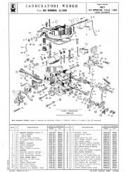
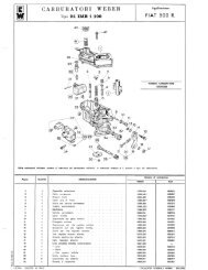
Figure 10: DHSA1 Carburetor Base Plate 19<br />
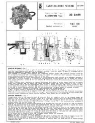
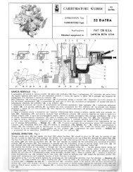
Figure 11: DHSA 20<br />
Figure 12: DHSA External Parts, Float Mechanisms, <strong>and</strong> Choke Assembly 21<br />
Figure 13: DHSA Jetting, Throttle Mechanisms, <strong>and</strong> Internal Parts 21<br />
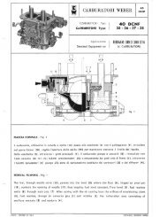
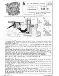
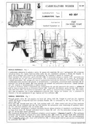
Figure 14: Weber 40 IDF Carburetor Side View 22<br />
Figure 15: IDF Normal Operation 22<br />
Figure 16: IDF Progression 23<br />
Figure 17: IDF Acceleration 24<br />
Figure 18: IDF Cold Start Devices 24<br />
Figure 19: IDF Dimensions 25<br />
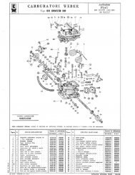
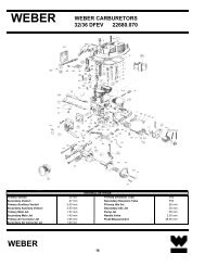
Figure 20: DMS Carburetor Side View 26<br />
Figure 21: DMS Normal Operation 26<br />
Figure 22: DMS Progression 27<br />
Figure 23: DMS Acceleration 28<br />
Figure 24: DMS Starting 29<br />
Figure 25: DMS Dimensions 30<br />
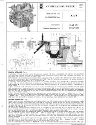
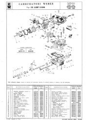
Figure 26: ADF Carburetor Side View 30<br />
Figure 27: ADF Normal Operation 31<br />
Figure 28: ADF Idle Speed <strong>and</strong> Progression 32<br />
Figure 29: ADF Acceleration 32<br />
Figure 30: ADF Starting 33<br />
Figure 31: ADF Anti-Pollution Device 34<br />
Figure 32: ADF Dimensions 35<br />
Figure 33: Bosch L-Jetronic Fuel Injection as used in the FIAT Spider 2000. 39<br />
Figure 34: Cold Start Operation in the Bosch L-Jetronic System 41<br />
Figure 35: Warm-up Operation in the Bosch L-Jetronic System 42<br />
Figure 36: Idle Speed Control in the Bosch L-Jetronic System 43<br />
Figure 37: Idle speed controls on the Spider 2000 49<br />
Figure 38: Primary Connections on the Electronic Control Unit 50<br />
Figure 39: Primary Fuel Injection Circuits 51<br />
Figure 40: Fuel Injection System Electrical Diagram 52<br />
Figure 41.1: Intake 60<br />
Figure 41.2: Compression 60<br />
Figure 41.3: Ignition 60<br />
Figure 41.4: Exhaust 60<br />
Figure 42: Initial Ignition Setting 69<br />
Figure 43: Final Timing (2000cc engine) 70<br />
89