Engine Maintenance and Modification Bradley Artigue
FIAT 124 Spider Engine Maintenance + Modification - Artigue.com
FIAT 124 Spider Engine Maintenance + Modification - Artigue.com
- No tags were found...

You also want an ePaper? Increase the reach of your titles
YUMPU automatically turns print PDFs into web optimized ePapers that Google loves.
FIAT 124 Spider<br />
<strong>Engine</strong> <strong>Maintenance</strong> + <strong>Modification</strong><br />
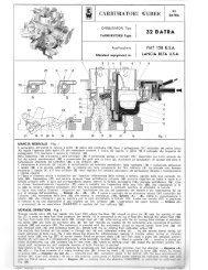
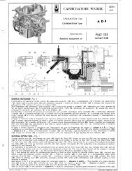
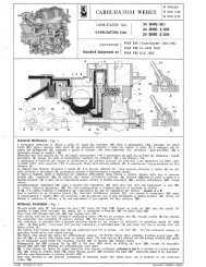
Figure 27: ADF Normal Operation<br />
Through needle valve (1), fuel passes into bowl (16) where the float (17), hinged on pivot<br />
pin (19) sets the opening of needle (20) in order to keep fuel level constant: the needle<br />
(20) is connected to the lug of float (17) through the return hook (18). The fuel, from bowl<br />
(16) reaches wells (14) through main jets (15). After mixing with the air coming from<br />
orifices of emulsion tubes (13) end from air corrector jets (6), the fuel reaches, vie<br />
nozzles (8), the carburetion area consisting of auxiliary venturis (7) end venturis (9).<br />
The carburetor is provided with the enrichment circuit on second barrel: from bowl (16),<br />
the fuel, through duct (10) end calibrated bush (2), blends with the air coming from<br />
calibrated orifices (3). The mixture thus formed will be sucked — through duct (4) end<br />
calibrated pipe (5) — by the second barrel during full power operation at high r.p.m.<br />
Fig. 1 also shows the device for differentiated opening of throttle valve. Acting on<br />
throttles control lever (25), this will first travel a given idle distance: primary throttle (23)<br />
— fitted on spindle (24) — will open of a corresponding angle, while secondary throttle<br />
(12) — fitted on spindle (11) — remains in closed position. Successively, lever (25)<br />
contacts free lever (22), which by shifting lever (21) makes the secondary spindle (11)<br />
rotate until contemporary end complete opening of both throttles is reached.<br />
Also shown in Fig. I is the control system for crankcase emission — diagrams A <strong>and</strong> B.<br />
— This consists of a rotary blanking disc (29) driven by shaft (24) controlled by lever (25)<br />
which, by means of groove (26) — diagrams A <strong>and</strong> B — connects pipe (28) conveying<br />
gases to be sucked, with the area downstream of throttle (23).<br />
Even by throttle (23) in idle position — diagram A — goes on conveyance of sucked<br />
gases metered by calibrated orifice (27).<br />
31