WRS-2224 Operator's Manual - Douglas Lighting Control
WRS-2224 Operator's Manual - Douglas Lighting Control
WRS-2224 Operator's Manual - Douglas Lighting Control
- No tags were found...

Create successful ePaper yourself
Turn your PDF publications into a flip-book with our unique Google optimized e-Paper software.
<strong>WRS</strong>-<strong>2224</strong><br />
Programmable Relay Scanner<br />
Instruction <strong>Manual</strong><br />
DOUGLASR<br />
lighting controls
Technical<br />
demandflex Dialog Series<br />
Lamp Performance<br />
WRV-DF-232NA<br />
T8 Lamps<br />
Lamp<br />
Type<br />
F32T8<br />
Qty<br />
2<br />
1<br />
Input<br />
Max Watts<br />
Min Watts<br />
120/277/347<br />
58/57/57<br />
19/18/18<br />
31/31/30<br />
11/11/11<br />
Ballast Factor<br />
MAX/MIN<br />
0.87/0.05<br />
0.87/0.05<br />
Max<br />
Input Current<br />
(Amps)<br />
.48/.21/.16<br />
.26/.11/.09<br />
BEF*<br />
At Full Bright<br />
Min<br />
Power<br />
Factor<br />
Max Thd<br />
(%)<br />
Min<br />
Crest<br />
Factor<br />
1.53 98 10%
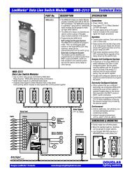
Introduction<br />
<strong>WRS</strong>-<strong>2224</strong> Programmable Relay Scanner<br />
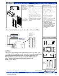
The <strong>WRS</strong>-<strong>2224</strong> Scanner can be programmed so that when an input is signalled ON or OFF, it switches a<br />
specific group of output relays ON or OFF. The <strong>WRS</strong>-<strong>2224</strong> has 5 inputs and 24 relay outputs.<br />
Each input can be have a unique relay group programmed to it. In addition to the basic ON and OFF<br />
commands, an input can have the optional switching features of 'Flick-Warn' and 'Time-Out'.<br />
24V Transformer<br />
Connections<br />
Relay Output Connections<br />
24 outputs, 12 per side.<br />
The relay scanner can be programmed<br />
with the built-in keypad to switch a group<br />
of relay outputs when signaled by an<br />
input. There are 5 groupings (5 inputs)<br />
available.<br />
Each group can support the FLICK WARN<br />
switching option, while only one group<br />
can be programmed to support the TIME<br />
OUT option.<br />
Digital Link Connection<br />
Allows the scanner to be linked to a network or another system.<br />
There are modules available for:<br />
a. RS-485 Network on new line Proprietary<br />
Communications Protocol;<br />
b. FTT-10 Network on new line Lonworks<br />
Open Standard Protocol.<br />
Group Input Connections<br />
5 available, each controlling one relay<br />
group.<br />
Up to 6 low-voltage switching devices can<br />
be connected in parallel to each input.<br />
Separate electrically isolated 24V return<br />
connections provided for groups 1, 2 & 3<br />
and for groups 4 & 5.<br />
DOUGLAS<br />
<strong>WRS</strong>-<strong>2224</strong>: Directions & Applications page 1 lighting controls
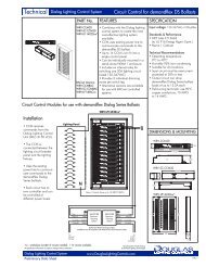
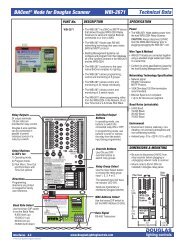
Parts & Dimensions<br />
Relay Outputs<br />
24 output terminals<br />
(12 per side) are provided<br />
for individual relay control.<br />
<strong>Douglas</strong> 2-wire switches can<br />
be connected in parallel to<br />
permit individual control of a<br />
relay by a switch.<br />
Individual Output LEDs<br />
In NORMAL mode, LEDs display<br />
if the relay is ON or OFF.<br />
In PROGRAM mode, LEDs display<br />
if the relay is included in the<br />
group that is being programmed<br />
to the selected group input.<br />
Mode Select Buttons & LEDs<br />
NORMAL mode.<br />
PROGRAM mode.<br />
OPTIONS mode:<br />
a. FLICK WARN after OFF;<br />
b. TIME OUT after ON;<br />
c. TIME OUT with FLICK WARN.<br />
Directions<br />
Directions are printed on the<br />
keyboard for handy user reference.<br />
Individual Output Buttons<br />
In NORMAL mode, use these buttons to<br />
switch the connected relay ON or OFF.<br />
In PROGRAM mode, use these buttons<br />
to enter or remove the connected relay<br />
to/from the group being programmed.<br />
Master Switch 0verride Buttons<br />
Use these buttons to switch all of<br />
the relays in a selected input<br />
group ON or OFF.<br />
Input Select Button<br />
Use this button to select the relay<br />
groups/switch inputs 1, 2, 3, 4 or 5.<br />
Group Switch Inputs (5)<br />
Connect <strong>Douglas</strong> 2-wire switches to<br />
switch the group of relays ON or OFF.<br />
You can connect up to 6 switches<br />
and/or 2-wire timer outputs to the<br />
same switch input.<br />
Digital Link <strong>Control</strong> Socket<br />
Plug-in for a RS-485 or Lonworks<br />
network interface such as a<br />
<strong>Douglas</strong> WNX-2624 module.<br />
Dimensions<br />
6.5"<br />
(165 mm)<br />
1<br />
2<br />
3<br />
4<br />
5<br />
6<br />
7<br />
8<br />
9<br />
10<br />
11<br />
12<br />
13<br />
14<br />
15<br />
16<br />
17<br />
18<br />
19<br />
20<br />
21<br />
22<br />
23<br />
24<br />
4.0"<br />
(103 mm)<br />
Plan View<br />
1.75"<br />
(45 mm)<br />
Side View<br />
Relay Scanners mount to 35mm DIN rail<br />
installed in relay panels.<br />
Each unit is shipped with DIN mounting rail.<br />
DOUGLAS<br />
<strong>WRS</strong>-<strong>2224</strong>: Directions & Applications page 2 lighting controls
Specifications<br />
Specifications<br />
General<br />
Power:<br />
24VAC / 50mA Class 2 Low Voltage device.<br />
Power rating does not include power used to switch relays.<br />
Master Switches:<br />
There are 5 master switch inputs that are compatible<br />
with all models of <strong>Douglas</strong> relay switches.<br />
A maximum of 6 switches can be connected in parallel to<br />
the same master switch input.<br />
Maximum wire length for a master switch is 2000'.<br />
(600m) if using 18 AWG wire.<br />
Digital Link:<br />
Programmable scanners have a digital link socket<br />
that permits connection of network communication<br />
modules.<br />
Programming<br />
Use the membrane keypad built into the face of<br />
the programmable relay scanner to assign relay<br />
groups to each of the master switch inputs.<br />
Program settings (relay groups) are not lost in the<br />
event of a power outage.<br />
Programming directions are printed into the front<br />
cover for handy reference.<br />
Environment<br />
Indoors, stationary, non-vibrating, non-corrosive<br />
atmosphere and non-condensing humidity.<br />
Ambient operating temperature:<br />
0 O F to +120 0 F (-15 O to +50 O C).<br />
Outputs<br />
24 <strong>Douglas</strong> relay outputs.<br />
Outputs fire in sequence (
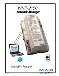
Installation<br />
INSTALLATION INSTRUCTIONS<br />
1. Install the <strong>WRS</strong>-<strong>2224</strong> Programmable Relay<br />
Scanner inside the relay panel. The scanner<br />
mounts to 35mm DIN rail, as shown in the<br />
drawing to the right. Mounting rail is supplied<br />
with each scanner unit.<br />
Outputs<br />
1-12<br />
2. Connect the red terminal of each relay to an<br />
Inputs<br />
output terminal of the scanner. You should<br />
1-5<br />
use 18 AWG wire. In most instances, If there<br />
are<br />
more than 24 relays, install additional scanners.<br />
DIN Rail<br />
3. Connect the group switching devices (switch or timer) to the scanner's<br />
group inputs. If you are connecting 24V contact switching devices other<br />
than a <strong>Douglas</strong> switch or time clock, you must first configure the inputs<br />
for a 24V contact. Use the keyboard on the scanner, as detailed in the<br />
'Input Configuration' section on page 6 of this manual.<br />
1<br />
2<br />
3<br />
4<br />
5<br />
6<br />
7<br />
8<br />
9<br />
10<br />
11<br />
12<br />
13<br />
14<br />
15<br />
16<br />
17<br />
18<br />
19<br />
20<br />
21<br />
22<br />
23<br />
24<br />
Outputs<br />
13-24<br />
4. A maximum of 6 switching devices can be connected in parallel to<br />
the same master input, with a maximum wire length of<br />
2000'/600m if using 18 AWG wire. Refer to the Switch Inputs<br />
section below for more information on input switching devices.<br />
5. After all the output relays have been assigned to lighting loads,<br />
determine which relays are to be switched together as groups.<br />
6. Use the keypad built into the front surface of the scanner to assign<br />
relay groups to be switched by each input. Refer to the SETUP<br />
pages of this manual and the directions printed on the scanner for<br />
details.<br />
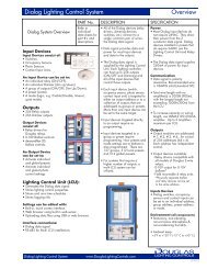
Switch Inputs<br />
Switching with Momentary<br />
Contacts that use Diodes<br />
ON & OFF switching with contacts from another<br />
device or system is best accomplished with<br />
momentary type contacts that have a diode<br />
connected in series (one contact and diode for ON<br />
and another for OFF).<br />
Momentary contacts that utilize diodes have 2<br />
advantages:<br />
1. It is possible to have repeat ON or OFF<br />
commands. For example, during the night, an<br />
OFF signal could be issued every hour to ensure<br />
lights are swept OFF.<br />
2. <strong>Douglas</strong> relay switches can be connected in<br />
parallel for convenient override.<br />
Momentary contacts with diodes mimic the<br />
<strong>Douglas</strong> relay switch. Thus, the default input<br />
configuration of the <strong>WRS</strong>-<strong>2224</strong> scanner is for<br />
the <strong>Douglas</strong> WR-8501 relay switch.<br />
Switching with 24V<br />
Momentary or Maintained<br />
Contacts (no Diodes)<br />
Inputs for the <strong>WRS</strong>-<strong>2224</strong> can also be configured to<br />
accept 24V signals that have no diode connected.<br />
The signal can be momentary or maintained.<br />
When using the 24V contact control, be aware<br />
there are some restrictions. An input can be<br />
configured to switch relays ON when 24V is applied<br />
and OFF when it is removed. However, when this<br />
is the case it is not possible to send repeat OFF<br />
signals without an intervening ON signal. You can<br />
also configure the input so that only OFF signals<br />
are sent if a repeat signal is desired, although in<br />
this case there would be no ON signal. Should<br />
repeat OFF as well as ON signals be needed, then<br />
two 24V contacts would be needed with two<br />
inputs, one for the OFF signal and one for the ON.<br />
Refer to 'Input Configuration Mode' on page 6 for<br />
all the settings available for 24V contact control.<br />
1<br />
2<br />
3<br />
4<br />
5<br />
6<br />
7<br />
8<br />
9<br />
10<br />
11<br />
12<br />
Momentary ON Contact<br />
OFF Contact<br />
ON<br />
Diode<br />
OFF<br />
Diode<br />
Master Sw Override<br />
Red<br />
<strong>Douglas</strong> switch OK with<br />
momentary contacts.<br />
NOT OK with maintained<br />
contacts.<br />
Maintained Form C<br />
Contact Set<br />
Coil<br />
1<br />
2<br />
3<br />
4<br />
5<br />
6<br />
7<br />
8<br />
9<br />
10<br />
11<br />
12<br />
NO NC<br />
COM<br />
13<br />
14<br />
15<br />
16<br />
17<br />
18<br />
19<br />
20<br />
21<br />
22<br />
23<br />
24<br />
<strong>WRS</strong>-<strong>2224</strong><br />
Relay<br />
Scanner<br />
13<br />
14<br />
15<br />
16<br />
17<br />
18<br />
19<br />
20<br />
21<br />
22<br />
23<br />
24<br />
W B<br />
1<br />
2<br />
3<br />
SwitchB Inputs 45<br />
B<br />
ON Diode<br />
OFF Diode<br />
(OR)<br />
B<br />
W<br />
Tr<br />
<strong>Douglas</strong> Relay Switches<br />
The inputs of the <strong>WRS</strong>-<strong>2224</strong> scanner<br />
are compatible with all models of<br />
<strong>Douglas</strong> relay switches. However, If<br />
you are connecting a different switch<br />
type, you must re-configure the input<br />
before connecting the switch. Follow<br />
the procedure described in the 'Input<br />
Configuration' section of this manual.<br />
When connected to the scanner, the<br />
LEDs of a <strong>Douglas</strong> switch will show the<br />
state of the relay group. If any of the<br />
relays in the group are ON, the group<br />
is defined as being ON and the red LED<br />
is lit. Only when all of the relays in the<br />
group are OFF is the group defined as<br />
being OFF and the green LED is lit.<br />
Take care when using <strong>Douglas</strong> WR-<br />
8501 switches. The WR-8501 push<br />
button switch will always send a signal<br />
that is opposite to its displayed state. If<br />
repeat ON or OFF control is desired, use<br />
the WR-8001 rocker switch which is<br />
able to select an ON or OFF signal.<br />
<strong>Douglas</strong> Timer Automation<br />
The inputs of the <strong>WRS</strong>-<strong>2224</strong> scanner<br />
are compatible with <strong>Douglas</strong> timers,<br />
such as the WTP-4408. When<br />
connecting a <strong>Douglas</strong> timer to the <strong>WRS</strong>-<br />
<strong>2224</strong> scanner, the input must be<br />
configured for a <strong>Douglas</strong> relay switch<br />
(default).<br />
1<br />
2<br />
3<br />
4<br />
5<br />
6<br />
7<br />
8<br />
9<br />
10<br />
11<br />
12<br />
1<br />
2<br />
3<br />
4<br />
5<br />
6<br />
7<br />
8<br />
9<br />
10<br />
11<br />
12<br />
13<br />
14<br />
15<br />
16<br />
17<br />
18<br />
19<br />
20<br />
21<br />
22<br />
23<br />
24<br />
<strong>WRS</strong>-<strong>2224</strong><br />
Relay<br />
Scanner<br />
Switch<br />
Inputs<br />
WR-8001 Rocker Switch<br />
Red<br />
13<br />
14<br />
15<br />
16<br />
17<br />
18<br />
19<br />
20<br />
21<br />
22<br />
23<br />
24<br />
W B<br />
WR-8501 Pushbutton<br />
Switch with<br />
ON & OFF LEDs<br />
1<br />
2<br />
3<br />
B 45<br />
B<br />
Red<br />
Red<br />
WTP-4408<br />
Time Clock<br />
A B C D<br />
1 2 3<br />
1 2 3<br />
Esc<br />
4 5 6<br />
4 5 6 7 8 9<br />
0 7 8 9<br />
0<br />
5 A I H<br />
5 A I H<br />
Maximum:<br />
6 switches<br />
<strong>WRS</strong>-<strong>2224</strong>: Directions & Applications page 4 lighting controls<br />
Clr<br />
9<br />
<br />
!<br />
"#$%&<br />
9<br />
*<br />
B<br />
W<br />
Tr<br />
DOUGLAS
Basics: Normal Mode<br />
NORMAL MODE<br />
Allows the connected relays to be switched with<br />
the scanner.<br />
Output Terminals<br />
Output Leds<br />
Output Buttons<br />
To Use Normal Mode:<br />
1. Make sure the individual relays are properly connected to the<br />
output terminals.<br />
2. The <strong>WRS</strong>-<strong>2224</strong> Scanner will usually be in NORMAL mode. If left in<br />
PROGRAM mode, it will revert to NORMAL mode after 2 minutes.<br />
If the NORMAL MODE indicator LED is OFF, press its select<br />
button to exit the PROGRAM mode. The NORMAL MODE<br />
indicator LED should turn ON.<br />
3. In NORMAL MODE, the output LED will be ON if the connected<br />
relay is on.<br />
To switch any relay ON/OFF, press its output button.<br />
4. A flashing LED indicates:<br />
(a) There is a defect in the relay (or)<br />
(b) There are 2 relays connected to the same terminal with one<br />
relay ON and the other OFF.<br />
Normal Mode<br />
Select Button<br />
Basics: Version Number Basics: Normal Mode<br />
VERSION NUMBER DISPLAY<br />
When you are in NORMAL mode and press the NORMAL<br />
MODE select button, some output LEDs, as well as the<br />
button's indicator LED, will flash for 10 seconds.<br />
The combination of flashing output LEDs 1-8 (left output<br />
terminal) indicate the version number -in binary code- of<br />
the Relay Scanner.<br />
If any of the output LEDs 13-20 (right output terminal) are<br />
flashing, their combination indicates the version number<br />
-in binary code- of the WNX-2624 Network Node attached<br />
to the Scanner's Digital Link.<br />
1. Any flashing output LEDs 1-8 indicate the version number of<br />
the Relay Scanner, with any flashing LEDs 1-4 indicating the<br />
integer after the decimal point and any flashing LEDs 5-8<br />
indicating the integer before the decimal point.<br />
2. The combination of flashing numbers #1-4 and #5-8 denote<br />
the integer in binary code (see the insert at upper right).<br />
3. When a Network Node is attached to the Digital Link, some of<br />
the output LEDs 13-20 will be flashing. They indicate the<br />
version number of the Network Node, with the combination of<br />
flashing LEDs 13-16 indicating the integer after the decimal<br />
point and the combination of flashing LEDs 17-20 indicating<br />
the integer before the decimal point.<br />
4. See the insert at lower right for examples of flashing LED<br />
combinations for version numbers that may currently be in use.<br />
Binary Code<br />
BINARY CODE is a method of<br />
expressing all whole numbers as<br />
some combination of powers of the<br />
number 2.<br />
A power of 2 is the number of<br />
times 2 is multiplied by itself, where<br />
2 O =1, 2 1 =2, 2 2 =4, 2 3 =8, etc.<br />
In binary code, the number one<br />
would be 2 O , the number two would<br />
be 2 1 , the number three would be<br />
2 0 +2 1 (1+2), and the number four<br />
would be 2 2 . In like manner, you<br />
can express all whole numbers as<br />
either a power of 2 or as a combination<br />
of two or more powers of 2.<br />
Scanner Version #<br />
Node Version #<br />
LEDs Flashing<br />
3.0 #5, #6<br />
3.1 #1, #5, #6<br />
3.2 #2, #5, #6<br />
3.3 #1, #2, #5, #6<br />
3.4 #3, #5, #6<br />
LEDs Flashing<br />
4.0 #19<br />
4.1 #13, #19<br />
4.2 #14, #19<br />
4.3 #13, #14, #19<br />
4.4 #15, #19<br />
Equivalent<br />
Numbers Flashing LEDs<br />
0 = none (none flashing)<br />
1 = 2 0 first<br />
2 = 2 1 second<br />
3 = 2 0 +2 1 first & second<br />
4 = 2 2 third<br />
5 = 2 0 +2 2 first & third<br />
6 = 2 1 +2 2 second & third<br />
7 = 2 0 +2 1 +2 2 first, second & third<br />
8 = 2 3 fourth<br />
DOUGLAS<br />
<strong>WRS</strong>-<strong>2224</strong>: Directions & Applications page 5 lighting controls
Setup: Input Configure Mode<br />
INPUT CONFIGURE MODE<br />
Allows specifying which type(s) of switching hardware can be<br />
connected to each group switch input.<br />
The default switch type for all inputs is the <strong>Douglas</strong> WR-8501<br />
with Led Indicators. This configuration is compatible with all<br />
models of <strong>Douglas</strong> relay switches, relay time clocks and photo<br />
cells and no re-configuration is necessary for those devices.<br />
However, if you will be connecting any different switch type(s)<br />
to an input, follow this procedure.<br />
To Use Input Configure Mode:<br />
1. Make sure NORMAL MODE is selected. Its top indicator light should be ON.<br />
2. Use the INPUT SELECT BUTTON to scroll to the group input #1-5 you<br />
wish to configure (when its INPUT LED is ON).<br />
3. Press and hold the OPTIONS MODE select button. The FLICK WARN LED<br />
will begin flashing.<br />
4. One of the OUTPUT LEDs #13-23 will display, showing the current<br />
configuration selected for the input. Refer to the table below for a list of all<br />
available configurations. The factory default is #21, the <strong>Douglas</strong> WR-<br />
8501 LED indicator rectified AC pulse switch.<br />
5. Depress the OUTPUT SELECT BUTTON(S) (#13-23) to select the desired<br />
configuration(s) for the input.<br />
You have 10 seconds to do this. After 10 seconds, the FLICK WARN LED<br />
stops flashing and the scanner reverts to NORMAL mode.<br />
6. Repeat steps 2-5 to configure other group inputs.<br />
Flick<br />
Warn<br />
LED<br />
Options Mode<br />
Select Button<br />
Output Buttons<br />
#13-#23<br />
Output LEDs<br />
#13-#23<br />
Input<br />
LEDs<br />
Normal Mode<br />
Select Button<br />
Input<br />
Select<br />
Button<br />
Output Button<br />
Pressed<br />
13<br />
14<br />
15<br />
Switch Type Configured for<br />
AC<br />
Momentary<br />
Contact.<br />
Action<br />
(13) - ON when switched<br />
(14) - OFF when switched<br />
(15) - OPEN=OFF / CLOSED=ON<br />
16<br />
17<br />
18<br />
Coil<br />
AC<br />
Maintained<br />
Contact.<br />
(16) - OPEN=ON / CLOSED=OFF<br />
(17) - OPEN=no action / CLOSED=ON<br />
(18) - OPEN=no action / CLOSED=OFF<br />
19<br />
(19) - OPEN=ON / CLOSED=no action<br />
20<br />
21 (Default)<br />
22<br />
23<br />
LEDs<br />
Rectified AC Pulse.<br />
Current for Indicator LEDs.<br />
NOTE: Non-LED switches are also<br />
compatible with this configuration.<br />
Rectified AC Pulse.<br />
No current for Indicator LEDs.<br />
NOTE: LED switches will not function<br />
properly with this configuration.<br />
Table 1. Switch Hardware Type<br />
(20) - OPEN=OFF / CLOSED=no action<br />
(21) - Positive=OFF / Negative=ON<br />
(22) - Positive=ON / Negative=OFF<br />
(23) - Positive=OFF / Negative=ON<br />
DOUGLAS<br />
<strong>WRS</strong>-<strong>2224</strong>: Directions & Applications page 6 lighting controls
Setup: Program Mode<br />
PROGRAM MODE<br />
Allows output relays to be grouped, with each group<br />
controlled by a switch input.<br />
Output<br />
Buttons<br />
Output<br />
LEDs<br />
To Use Program Mode:<br />
1. Make sure the output relays are properly connected to the output<br />
terminals and that the group switches and/or timer outputs are<br />
properly connected to the input terminals.<br />
2. Make sure NORMAL MODE is selected. The top indicator LED of<br />
the NORMAL MODE select button should be ON.<br />
3. Use the INPUT SELECT button to scroll to the desired input #1-5<br />
(when its indicator INPUT LED is ON).<br />
4. Press the PROGRAM MODE select button. Its indicator light will<br />
begin flashing. The OUTPUT LEDs of the relays that are controlled<br />
by the selected input will be ON.<br />
5. Add or remove output relays from the selected input by pressing<br />
the OUTPUT button of the desired relay.<br />
6. When you have selected all the relays for the group, press the<br />
NORMAL MODE select button to return to NORMAL mode.<br />
7. Repeat steps #3 - 6 to program other inputs with a relay group.<br />
NOTE: A relay can be in more than one group.<br />
8. When you are programming a relay group, you can include or<br />
exclude all the output relays by pressing the ON OVERRIDE or OFF<br />
OVERRIDE button, respectively.<br />
9. When you are in NORMAL mode, you can turn all the relays<br />
assigned to an input ON or OFF by selecting that input with the<br />
INPUT SELECT button, and then pressing the ON OVERRIDE or<br />
OFF OVERRIDE button.<br />
NOTE:<br />
If there is 2 minutes of inactivity during<br />
PROGRAM mode, the scanner will revert to<br />
NORMAL mode.<br />
To return to PROGRAM mode, press the<br />
PROGRAM MODE selectbutton.<br />
Input<br />
LEDs<br />
Program Mode<br />
Select Button<br />
Normal Mode<br />
Select Button<br />
ON Override<br />
Select Button<br />
OFF Override<br />
Select Button<br />
Input<br />
Select Button<br />
Input<br />
Terminals<br />
DOUGLAS<br />
<strong>WRS</strong>-<strong>2224</strong>: Directions & Applications page 7 lighting controls
Setup: Flick Warn Option<br />
FLICK WARN OPTION<br />
Allows any relay group to have the FLICK WARN feature.<br />
FLICK WARN warns occupants that the lights will be switched<br />
OFF in 5 minutes.<br />
Occupants can cancel the OFF sweep for the local circuit by<br />
flicking the local switch. Or, they can cancel the OFF sweep for<br />
the entire group by pressing the group's input switch once.<br />
9<br />
12<br />
PM<br />
3<br />
FLICK WARN Sequence<br />
1<br />
2 3 4<br />
OFF<br />
6<br />
Sw<br />
Sw Sw Sw<br />
OFF Signal<br />
Lights flash to<br />
warn of OFF<br />
Occupant has<br />
5 minutes to<br />
cancel OFF<br />
If cancelled,<br />
lights stay ON<br />
If not cancelled,<br />
lights go OFF<br />
To Assign the Flick Warn Option:<br />
1. Make sure the output relays are properly connected to the output<br />
terminals and that the group switches and/or timer outputs are<br />
properly connected to the input terminals.<br />
2. Make sure NORMAL MODE is selected. Its top indicator LED should<br />
be ON.<br />
3. Use the INPUT SELECT button to select the desired group #1-5<br />
(when its indicator INPUT LED is ON).<br />
4. Press the PROGRAM MODE select button. Its indicator LED will<br />
begin flashing. If you have not already done so, select the output<br />
relays that belong to that input's group.<br />
5. Press the OPTIONS MODE select button once. The FLICK WARN<br />
indicator LED will turn on. (Pressing the OPTIONS MODE button<br />
will cycle the selections from FLICK WARN to TIME OUT to TIME<br />
OUT with FLICK WARN back to NO SELECTION.)<br />
6. Return to NORMAL mode.<br />
7. Repeat steps #3 - 6 to assign the FLICK WARN option to another<br />
group.<br />
8. For any group assigned the FLICK WARN option, the FLICK WARN<br />
indicator LED will be ON whenever the group is selected and the<br />
FLICK/TIME-OUT ACTIVE LED will flash whenever the flick warning<br />
operation is occurring.<br />
Flick Warn<br />
LED<br />
Output Mode<br />
Select Button<br />
Program Mode<br />
Select Button<br />
Input<br />
Select<br />
Button<br />
Time Out<br />
LED<br />
Input<br />
LEDs<br />
Normal Mode<br />
Select Button<br />
Flick/<br />
Time Out<br />
Active LED<br />
To De-Assign the Flick Warn Option:<br />
1. Select the group (with INPUT SELECT).<br />
2. Go to PROGRAM mode.<br />
3. Press the OPTIONS button (usually 3 times) so that both the<br />
FLICK WARN LED and TIME OUT LED are OFF.<br />
4. Return to NORMAL mode.<br />
NOTE:<br />
Assigning the FLICK WARN option to a relay group that<br />
controls any HID lighting is NOT RECOMMENDED.<br />
(HID lights require more than 5 minutes to turn ON after<br />
being turned OFF.)<br />
DOUGLAS<br />
<strong>WRS</strong>-<strong>2224</strong>: Directions & Applications page 8 lighting controls
Setup: Time Out Option<br />
TIME OUT OPTION<br />
) M I A HA = O C H K F J D = L A JD A 6 1 - 7 6 BA = JK HA <br />
IMPORTANT1BJD A HA = O C H K F B= E F K JD = I JD A 6 1 - 7 6 <br />
BA = JK HA = I I EC A @ JD A E F K JM E not sM EJ? D JD A HA = O C H K F <br />
1 I JA = @ JD A E F K JM EA = > A JD A 6 1 - 7 6 BA = JK HA M D A <br />
JK H A @ = @ @ EI = > A JD A 6 1 - 7 6 BA = JK HA M D A JK H A @ BB<br />
1<br />
12<br />
PM<br />
9<br />
6<br />
Mode<br />
Change<br />
Sw<br />
3<br />
TIME OUT during Closed Hours<br />
2 3 4<br />
Sw<br />
Sw<br />
9 D A = ? JEL A 6 1 - 7 6 ? = K I A I JD A HA = O K JF K JJ I J= HJ= E JA H = <br />
JE A HM D A A L A HJD A ? A ? JA @ HA = O EI I M EJ? D A @ 7 F JE A <br />
A N F EHO D K HI = JA HJD A K JF K JI M EJ? D A I JD A HA = O . . <br />
6 1 - 7 6 EI JO F E? = O A = > A @ = @ @ EI = > A @ M EJD = JE A ? ? <br />
? A ? JA @ J JD A E F K J) I = ? A N = F A K I A JD A JE A <br />
? ? J A = > A 6 1 - 7 6 @ K HE C ? I A @ D K HI 6 D K I ? = <br />
I M EJ? D A I M EM H H = O @ K HE C > K I E A I I D K HI = @ BK ? JE <br />
M EJD 6 1 - 7 6 @ K HE C ? I A @ D K HI <br />
Sw<br />
5<br />
9<br />
OFF<br />
12<br />
3<br />
AM<br />
6<br />
Sw<br />
6<br />
Sw<br />
TIME OUT mode<br />
enabled at start of<br />
closed hours<br />
Light turned ON<br />
with wall switch:<br />
timer starts<br />
Exit without<br />
switching OFF<br />
Timer expires,<br />
lights switched OFF<br />
TIME OUT mode<br />
disabled at start of<br />
business hours<br />
Switches work normally<br />
(no TIME OUT) during<br />
business hours<br />
To Assign the Time Out Option:<br />
1. Make sure the output relays are properly connected to the output<br />
terminals and that the timer output is properly connected to the<br />
selected input terminal.<br />
2. Make sure NORMAL MODE is selected. Its top indicator LED should be ON.<br />
3. Use the INPUT SELECT button to select the designated group #1-5<br />
(when its indicator INPUT LED is ON).<br />
4. Press the PROGRAM MODE select button. Its indicator LED will begin<br />
flashing. If you have not already done so, select the output relays that<br />
belong to that input.<br />
5. Press the OPTIONS MODE button until the TIME OUT indicator LED<br />
turns ON. (Pressing the OPTIONS MODE button will cycle the<br />
selections from FLICK WARN to TIME OUT to TIME OUT with FLICK<br />
WARN back to NO SELECTION.)<br />
6. If you want to assign the TIME OUT option with a FLICK WARN to the<br />
group, press the OPTIONS MODE button until both the TIME OUT and<br />
the FLICK WARN indicator LEDs are ON.<br />
7. Return to NORMAL mode.<br />
8. For the group assigned the TIME OUT option, the TIME OUT indicator<br />
LED will be ON whenever the group is selected, and the FLICK/TIME<br />
OUT ACTIVE LED will flash whenever the TIME OUT operation is<br />
occuring.<br />
NOTE:<br />
Only one group can be assigned the TIME OUT option. If<br />
more than one group is assigned TIME OUT, those groups<br />
will not respond to input or override switch commands.<br />
It will be necessary, in that case, to shut off and restart the<br />
Relay Scanner, and then re-program all of the input groups<br />
with only one all-inclusive group assigned TIME OUT.<br />
To De-Assign the Time Out Option:<br />
1. Select the group (with INPUT SELECT).<br />
2. Go to PROGRAM mode.<br />
3. Press the OPTIONS button so that both the TIME OUT and the<br />
FLICK WARN indicator LEDs are OFF.<br />
4. Return to NORMAL mode.<br />
Flick Warn<br />
LED<br />
Output Mode<br />
Select Button<br />
Program Mode<br />
Select Button<br />
Input<br />
Select<br />
Button<br />
Time Out<br />
LED<br />
Input<br />
LEDs<br />
Normal Mode<br />
Select Button<br />
Flick/Time Out<br />
Active LED<br />
Scanner Input<br />
When set in TIME OUT mode,<br />
the time clock enables TIME OUT<br />
with an ON signal and disables<br />
TIME OUT with an OFF signal.<br />
Relays that are assigned to the<br />
group are not switched.<br />
WTP-4408<br />
Time Clock<br />
A B C D<br />
1 2 3<br />
1 2 3<br />
Esc<br />
4 5 6<br />
4 5 6 7 8 9<br />
0 7 8 9<br />
0<br />
5 A I H<br />
5 A I H<br />
Clr<br />
9<br />
<br />
!<br />
"#$%&<br />
9<br />
*<br />
DOUGLAS<br />
<strong>WRS</strong>-<strong>2224</strong>: Directions & Applications page 9 lighting controls
OPTIONS<br />
PGM<br />
NORMAL<br />
MODE<br />
INPUT<br />
SELECT<br />
ON<br />
OVERRIDE<br />
OFF<br />
OVERRIDE<br />
Connections: Stand Alone Panels<br />
Office Floor -Reflected Ceiling Plan<br />
Office<br />
Office<br />
Office Office Office<br />
Office<br />
Sw<br />
Sw<br />
Sw<br />
Office<br />
NW Quadrant<br />
Hall<br />
NE Quadrant<br />
Office<br />
Sw<br />
Office<br />
Library<br />
Storage<br />
Office<br />
Zones<br />
Office<br />
Sw<br />
Hall<br />
Elevator<br />
Office<br />
Hall<br />
Office<br />
NW Quadrant NE Quadrant<br />
Sw<br />
Hall<br />
Core<br />
Office<br />
Hall<br />
Reception<br />
Core<br />
Office<br />
SW Quadrant<br />
SE Quadrant<br />
Mens<br />
Office<br />
Office<br />
SW Quadrant<br />
Womens<br />
Hall<br />
Photo<br />
Copy<br />
Office<br />
SE Quadrant<br />
Office<br />
Office Office Office Office Office Office<br />
Individual<br />
Switches<br />
White<br />
Relay Panel<br />
Transformer<br />
W<br />
B 24VAC<br />
Group 1<br />
Relay #<br />
1<br />
2<br />
<strong>Lighting</strong> Circuit<br />
NW Priv Office<br />
NW Priv Office<br />
Relays<br />
1<br />
2<br />
3<br />
4<br />
5<br />
6<br />
7<br />
8<br />
9<br />
10<br />
11<br />
12<br />
Outputs<br />
1<br />
13<br />
2 14<br />
3<br />
15<br />
4 16<br />
5<br />
17<br />
6 18<br />
7<br />
19<br />
8 20<br />
9<br />
21<br />
10 22<br />
11<br />
23<br />
12 24<br />
13<br />
14<br />
15<br />
16<br />
17<br />
18<br />
19<br />
20<br />
21<br />
22<br />
23<br />
24<br />
Relays<br />
Group<br />
Switch<br />
Station<br />
3<br />
4<br />
5<br />
6<br />
NW Priv Office<br />
Library<br />
NW Priv Office<br />
NW Priv Office<br />
MODE<br />
<strong>WRS</strong>-<strong>2224</strong><br />
Relay<br />
Scanner<br />
Inputs<br />
W B<br />
WTP-4408<br />
Time Clock<br />
1<br />
2<br />
3<br />
B 45<br />
B<br />
NW<br />
Quad<br />
SW<br />
Quad<br />
NE<br />
Quad<br />
SE<br />
Quad<br />
Core<br />
Core<br />
Core<br />
A B C D<br />
1 2 3<br />
1<br />
4<br />
2<br />
5<br />
3<br />
6<br />
Esc<br />
Clr<br />
47 85 96<br />
7 0 8 9<br />
0<br />
5 A I H<br />
9<br />
<br />
!<br />
"#$%&<br />
5 A I H<br />
9<br />
*<br />
W<br />
24VAC<br />
Power<br />
DOUGLAS<br />
<strong>WRS</strong>-<strong>2224</strong>: Directions & Applications page 10 lighting controls
Connections: Stand Alone Panels<br />
Simple Stand Alone Panels<br />
The <strong>WRS</strong>-<strong>2224</strong> Programmable Relay Scanner permits a group of relays to<br />
be controlled with a single switch. The scanner can support up to 5<br />
groups of relays, each controlled by one of 5 switch inputs.<br />
In this example, the 24 output relays are divided into 4 groups, with each<br />
group controlling the lights in an area, or zone, of the Office. Group 1<br />
controls the lights in the NW Quadrant (shaded area in Ceiling Plan).<br />
Group 2 controls the SW Quadrant, Group 3 the NE Quadrant and Group 4<br />
the SE Quadrant. The Core circuits are controlled directly by a switch in<br />
the Group Switch Station.<br />
Use the keypad built into the front of the scanner to assign the relay<br />
groups. Changes to relay groups are easy to accomplish with the keypad;<br />
no rewiring is necessary. In this example, Relays #1-6 are assigned to<br />
Group 1.<br />
Install wall switches to provide for occupant override. They can be either<br />
individual wall switches connected directly to the relays or group switches<br />
connected to the scanner inputs.<br />
In this example, Relays #1-6, which comprise Group 1, are each<br />
connected to a wall switch in a Private Office, as shown in the diagram on<br />
the previous page.<br />
Another application, which can yield significant energy savings, is the use<br />
of the TIME OUT feature. During any period TIME OUT is activated, any<br />
lights in the designated TIME OUT group that are left on for 2 hours will<br />
be switched OFF automatically.<br />
In this example, Group 5, to which all of the relays on the floor are<br />
assigned, is programmed for the TIME OUT option. TIME OUT will be<br />
activated and de-activated by the WTP-4408 Timer connected to Group<br />
5's input terminal.<br />
The scanner can be set to provide groups with FLICK WARN, in which the<br />
lights flick to warn occupants they will be automatically shut off in 5<br />
minutes. Occupants can then cancel the OFF sweep by flicking the local<br />
switch or by pressing the group switch once.<br />
In this example, each of Groups #1-4 is programmed for FLICK WARN<br />
which is to occur 5 minutes before the OFF sweep time designated for<br />
that group by the WTP-4408 Timer. Group #5 is programmed for the<br />
FLICK WARN along with the TIME OUT option, so its flick warning will<br />
occur with any lights left on 2 hours when TIME OUT is enabled.<br />
DOUGLAS<br />
<strong>WRS</strong>-<strong>2224</strong>: Directions & Applications page 11 lighting controls
Nor<br />
Nor<br />
malMode<br />
malMode<br />
or<br />
malMode<br />
Nor<br />
Nor<br />
malMode<br />
malMode<br />
Connections: Multiple Panels<br />
Multiple Relay Panels<br />
In larger buildings, there often are several load centers that need to be<br />
controlled from one location.<br />
A simple wiring strategy is to interconnect the relay panels with a multiconductor<br />
bus. This method permits several building-wide controls to<br />
exist at each relay panel. Connect the relay panel's scanner inputs to<br />
the appropriate control wire of the bus.<br />
Projects that are interconnected with a multi-conductor bus should use<br />
a separate transformer to supply the multi-conductor bus.<br />
This is done so the power that switches the relays in each panel is<br />
isolated from the power used for the building-wide switching circuit.<br />
As all <strong>Douglas</strong> scanners have optically-isolated master switch inputs,<br />
the <strong>WRS</strong>-<strong>2224</strong> Relay Scanner in the panel will isolate the power in the<br />
bus signal from the power used in the panel.<br />
Lights<br />
Lights<br />
Lights<br />
Main Panel<br />
Rly<br />
Rly<br />
Rly<br />
Rly<br />
Rly<br />
<strong>WRS</strong>-<strong>2224</strong><br />
Scanner<br />
W<br />
B<br />
Tr<br />
Rly<br />
Rly<br />
Rly<br />
Rly<br />
Rly<br />
Rly<br />
Sw<br />
Sw<br />
Lights<br />
Lights<br />
Lights<br />
Sw<br />
Sw<br />
Lights<br />
Lights<br />
Lights<br />
Remote Panel<br />
Rly<br />
Rly<br />
Rly<br />
Rly<br />
Rly<br />
Rly<br />
Rly<br />
Rly<br />
Rly<br />
Rly<br />
<strong>WRS</strong>-<strong>2224</strong><br />
Scanner<br />
<strong>WRS</strong>-<strong>2224</strong><br />
Scanner<br />
Tr<br />
12345678 WB<br />
Rly<br />
Rly<br />
Rly<br />
Rly<br />
Rly<br />
Rly<br />
Rly<br />
Rly<br />
Rly<br />
Rly<br />
Rly<br />
Rly<br />
Rly<br />
Rly<br />
Rly<br />
Rly<br />
Rly<br />
Rly<br />
Lights<br />
Lights<br />
Lights<br />
Lights<br />
Lights<br />
Lights<br />
Lights<br />
Lights<br />
Lights<br />
Sw<br />
Sw<br />
Remote Panel<br />
Rly<br />
Rly<br />
Rly<br />
Rly<br />
Rly<br />
<strong>WRS</strong>-<strong>2224</strong><br />
Scanner<br />
Tr<br />
12345678 WB<br />
Rly<br />
Rly<br />
Rly<br />
Rly<br />
Rly<br />
Rly<br />
Rly<br />
Rly<br />
Rly<br />
Individual<br />
Occupant<br />
Switches<br />
Lights<br />
Lights<br />
Lights<br />
Sw<br />
Sw<br />
Sw<br />
Lights<br />
Lights<br />
Lights<br />
Rly<br />
Rly<br />
Rly<br />
Rly<br />
Rly<br />
Rly<br />
Rly<br />
Rly<br />
Rly<br />
Rly<br />
Rly<br />
<strong>WRS</strong>-<strong>2224</strong><br />
Scanner<br />
Rly<br />
Rly<br />
Rly<br />
Rly<br />
Rly<br />
Rly<br />
Rly<br />
Rly<br />
Rly<br />
Rly<br />
Rly<br />
Rly<br />
Rly<br />
Rly<br />
Lights<br />
Lights<br />
Lights<br />
Lights<br />
Lights<br />
Lights<br />
1 234<br />
56<br />
78<br />
24V W B<br />
Inter-Connected Panels<br />
A 10-conductor bus will provide eight master switch<br />
controls that can be used in several panels.<br />
Connect a master switch station and/or timer to the bus<br />
for override and automation.<br />
Sw 1<br />
Sw 4<br />
Sw 7<br />
Sw 3<br />
Sw 6<br />
Sw 2<br />
Sw 5<br />
Sw 8<br />
Group<br />
Switch<br />
Station<br />
W<br />
B<br />
WTP-4408<br />
Time Clock<br />
A B C D<br />
1 2 3<br />
Esc 1<br />
4<br />
2<br />
5<br />
3<br />
6<br />
Clr<br />
47 58 69<br />
7 0 8 9<br />
0<br />
Sensor<br />
Sensor<br />
W<br />
12345678<br />
W<br />
B<br />
12345678<br />
Global<br />
Transformer<br />
<strong>WRS</strong>-<strong>2224</strong>: Directions & Applications page 12 lighting controls<br />
W<br />
B<br />
DOUGLAS
Connections: Multiple Panels<br />
Relay Scanner Networks<br />
Another method of interconnecting load centers/relay panels is to use<br />
the <strong>Douglas</strong> WNX-2624 Network Node. With the WNX-2624 Node, you<br />
can network the <strong>WRS</strong>-<strong>2224</strong> Programmable Relay Scanner with a nonpolarized<br />
data signal to other <strong>WRS</strong>-<strong>2224</strong> Relay Scanners.<br />
Up to twenty-four <strong>WRS</strong>-<strong>2224</strong>/WNX-2624 scanner/node combinations<br />
can exist within a self-configured system.<br />
In a self-configured system, the input of one scanner can control relays<br />
that are connected to any of the scanners that are a part of the system.<br />
<strong>WRS</strong>-<strong>2224</strong><br />
Relay Scanner<br />
The WNX-2624 Network Node is LonMark compliant and can be<br />
integrated to be part of and to be controlled by another system.<br />
Relay Panel<br />
Relays<br />
R<br />
R<br />
R<br />
R<br />
R<br />
R<br />
R<br />
R<br />
R<br />
R<br />
R<br />
R<br />
Transformer<br />
24V<br />
Scanner<br />
WNX-2624<br />
Network Node<br />
Remote Panels<br />
w<br />
.<strong>Douglas</strong>LIghting<strong>Control</strong>s.com<br />
Node<br />
DOUGLAS<br />
<strong>WRS</strong>-<strong>2224</strong>: Directions & Applications page 13 lighting controls
Troubleshooting<br />
<strong>WRS</strong>-<strong>2224</strong> Troubleshooting Guide<br />
General Guidelines:<br />
Make sure that 24V power exists (always measure between 22V and<br />
30VAC);<br />
Make sure all inputs and outputs are tightly connected;<br />
Make sure all relay groups are programmed correctly;<br />
If non-default input switching devices are used, make sure all inputs are<br />
configured properly.<br />
Problem Encountered<br />
Flashing output LED(s)<br />
during NORMAL mode<br />
Output relay(s) not<br />
tripping properly<br />
FLICK WARN not working<br />
Possible Cause(s)<br />
Defective output relay<br />
2 relays connected to same output<br />
with one relay ON and the other OFF<br />
External AC current leaking into circuit<br />
Improper input voltage (must be<br />
between 22V and 30VAC)<br />
Input(s) not configured when non-default<br />
input switching device(s) used<br />
Relay(s) also part of another input group<br />
with contradictory input signals<br />
Relay(s) not included in input group<br />
FLICK WARN not properly programmed<br />
HID lighting used in FLICK WARN group<br />
Corrective Action<br />
- replace relay<br />
- reset relays<br />
- if either relay is in another input group,<br />
remove it from that group<br />
- check wiring<br />
- check input configuration<br />
- check input switching device(s) and connections<br />
- check power source<br />
- configure input(s) per instructions on page 6<br />
- remove relay(s) from other group<br />
- check programming, re-program if necessary<br />
- check programming, re-program if necessary<br />
- use circuits with non-HID lighting<br />
TIME OUT not working Inappropriate input switching device used - make sure input is only ON during TIME OUT period<br />
- use timer as input instead of switch<br />
Relay group not programmed properly<br />
TIME OUT assigned to more than one group<br />
- check programming, re-program if necessary<br />
- assign TIME OUT only to one all-inclusive group<br />
Table 2. <strong>WRS</strong>-<strong>2224</strong> Troubleshooting Guide<br />
DOUGLAS<br />
<strong>WRS</strong>-<strong>2224</strong>: Directions & Applications page 14 lighting controls
Appendix A - Input/Output Log<br />
Date<br />
Input Input Switches Output Relays<br />
Type Remarks # Remarks # Remarks<br />
1.<br />
Type Remarks # Remarks # Remarks<br />
2.<br />
Type Remarks # Remarks # Remarks<br />
3.<br />
Type Remarks # Remarks # Remarks<br />
4.<br />
Type Remarks # Remarks # Remarks<br />
5.<br />
Additional Remarks:<br />
DOUGLAS<br />
<strong>WRS</strong>-<strong>2224</strong>: Directions & Applications page 15 lighting controls
Notes<br />
DOUGLAS<br />
<strong>WRS</strong>-<strong>2224</strong>: Directions & Applications page 16 lighting controls
Notes<br />
DOUGLAS<br />
<strong>WRS</strong>-<strong>2224</strong>: Directions & Applications page 17 lighting controls
DOUGLASR<br />
lighting controls<br />
www.<strong>Douglas</strong><strong>Lighting</strong><strong>Control</strong>s.com<br />
4455 Juneau Street • Burnaby, B.C. • CANADA<br />
phone: (604) 873-2797 • fax: (604) 873-6939<br />
WARRANTY<br />
DOUGLAS products are warranted for one year from the<br />
date of purchase by the consumer against defects due<br />
to materials and the company's worksmanship only. The<br />
sole obligation hereunder shall be to repair, or at the<br />
company's option to replace, products as aforesaid,<br />
provided same are returned, upon authorization,<br />
'Transportation Prepaid' to the company's Burnaby,<br />
CANADA office within the said period. Defects or failures<br />
due to improper or careless installation, storage or<br />
handling, or usage other than rated conditions, are<br />
specifically excluded from this warranty. No liability is<br />
accepted for return transportation charges following<br />
repair or replacement as aforesaid or for reinstallation<br />
costs. No other liability of any nature or kind, whether<br />
arising out of or from the use of the product, whether or<br />
not defective, is assumed.<br />
DOUGLAS lighting controls reserves the right to cancel or<br />
change items shown in this publication without notice.