Dimension Icon AFM Instructions September.pdf
Dimension Icon AFM Instructions September.pdf
Dimension Icon AFM Instructions September.pdf

Create successful ePaper yourself
Turn your PDF publications into a flip-book with our unique Google optimized e-Paper software.
DIMENSION <strong>AFM</strong> ICON INSTRUCTIONS<br />
A. ScanAsyst<br />
B. Contact Mode <strong>AFM</strong><br />
C. Tapping Mode <strong>AFM</strong><br />
I. FACTORS TO TAKE INTO ACCOUNT BEFORE USING THE <strong>AFM</strong>:-<br />
a) DO NOT PLACE ANYTHING ON THE GRANITE STAGE AT ALL!!!!<br />
b) SPM SCANNER COSTS $25,000, HANDLE IT WITH CARE.<br />
c) DO NOT TOUCH THE LENS ON THE SPM HEAD.<br />
d) DO NOT STARE DIRECTLY AT THE LASER LIGHT<br />
II.<br />
INTRODUCTION TO THE BASIC IMAGING MODES OF <strong>AFM</strong><br />
a) ScanAsyst <strong>AFM</strong><br />
ScanAsyst imaging mode is the first image-optimization scanning mode for<br />
<strong>AFM</strong>. ScanAsyst continuously monitors image quality, and makes the appropriate<br />
parameter adjustments such as setpoints, feedback gains, and scan rates. ScanAsyst is<br />
based on Peak Force Tapping mode which collects force curves at every pixel in the<br />
image. The peak force of each of the force curves is used as the imaging feedback<br />
signal, hence providing direct force control. This enables it to operate at very low forces<br />
than Tapping Mode, which helps protect delicate samples and probes. Using ScanAsyst<br />
provides faster imaging while retaining high resolution images even for sticky samples.<br />
b) Tapping Mode <strong>AFM</strong><br />
The probe is oscillated near its resonance frequency and it intermittently interacts with<br />
the sample surface. Constant oscillation amplitude is used as a feedback mechanism to<br />
maintain a constant tip-sample interaction. Tapping mode minimizes shear forces,<br />
which can damage delicate samples. Topography and phase images are simultaneously<br />
acquired with tapping mode <strong>AFM</strong>. Samples which are delicate as well as with higher<br />
adhesive properties can be characterized using tapping mode <strong>AFM</strong>.<br />
c) Contact Mode <strong>AFM</strong><br />
Measures topography and lateral force image/friction by scanning the probe’s tip in a<br />
raster pattern on the sample surface while monitoring the cantilever deflection.<br />
Constant deflection between the cantilever and the sample is therefore used as<br />
feedback mechanism. In contact mode, the tip continuously remains in contact with the<br />
sample.<br />
d) For Magnetic Force Microscopy, Peak Force Quantitative NanoMechanics, Liquid<br />
Imaging, Force Imaging, Surface Potential and Peak Force TUNA:- Please consult<br />
Dr. Wilson K. Serem on instructions for these <strong>AFM</strong> modes.
Figure 1. Various components of <strong>AFM</strong> (from <strong>Icon</strong> <strong>AFM</strong> manual)
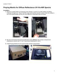
A. ScanAsyst: Step by Step (Nothing on Granite Stage)<br />
1. Tip Loading:<br />
<br />
<br />
<br />
<br />
<br />
<br />
Place the cantilever holder onto the cantilever holder stand.<br />
Press down and Pull the probe clip all the way to the back.<br />
Place the ScanAsyst <strong>AFM</strong> probe into the cantilever holder groove.<br />
Press down and gently push forward the tip holder clip to hold the<br />
cantilever.<br />
Loosen the screw on the right side of the SPM head to remove the<br />
SPM scanner ($25,000 is the cost of the SPM scanner).<br />
Carefully mount the <strong>AFM</strong> probe holder (tip placed) onto the SPM head.<br />
Figure 2. Loading <strong>AFM</strong> tip onto the Cantilever Holder (from <strong>Icon</strong> <strong>AFM</strong> manual)<br />
2. Sample Mounting: Mount your sample on the magnetic discs using scotch<br />
double-sided tape OR put it on the vacuum stage and turn on the vacuum by toggling<br />
the VACUUM switch.
3. CAMERA ALIGNMENT and LASER ALIGNMENT<br />
Double click the NanoScope icon on the desktop and Select SCANASYST<br />
(Figure 3)<br />
Figure 3. Experiment window showing different modes of <strong>AFM</strong> (taken from Bruker manual)<br />
<br />
Select SCANASYST IN AIR or SCANASYST IN FLUID in the Select<br />
Experiment Group.
Click Load Experiment to open the Workflow Toolbar, Scan Parameters List<br />
Scan One Channel and Force Monitor.<br />
Click SETUP in the Workflow Toolbar. Click Change probe and select the tip<br />
you want to use in the database or other/unknown cantilever if it is not in the<br />
database.<br />
It is easier to align the laser on the tip in the ALIGNMENT STATION. Click<br />
the ALIGNMENT STATION icon in the Align window. Zoom out as far as<br />
possible in case you cannot see the laser spot as well as the tip in the optical<br />
field of view. Align the laser using the laser control knobs.<br />
Click FOCUS UP or FOCUS DOWN to focus the cantilever. Adjust the<br />
illumination for better view. Move crosshair on the tip and move the laser<br />
position using the laser knobs on the tip of the cantilever to maximize the<br />
SUM value on the LCD display. Zoom out as far as possible.<br />
4. DETECTOR ALIGNMENT<br />
Adjust the photodetector using the two photodetector knobs so that the<br />
red dot is at the center of the <strong>Dimension</strong> head filter screen. Do fine<br />
adjustment to attain (0,0) for vertical and horizontal deflections<br />
respectively.<br />
5. Click Return from the Alignment Station and click “Yes” when prompted.<br />
6. FOCUSING THE SAMPLE:<br />
In the Workflow Toolbar, click NAVIGATE. RAISE THE SPM HEAD<br />
using SPM “up arrow” to make sure that there is enough space between the<br />
tip holder and the sample before the stage is rotated.<br />
Rotate the sample stage so that the laser light is falling on your sample. Use<br />
the trackball to position your sample if necessary. Focus on the surface by<br />
moving the SPM head up or down using the SPM “up arrow” or “down<br />
arrow”. CAUTION: be careful not to crash the SPM head into your<br />
sample.<br />
7. SCANNING PARAMETERS:<br />
Click CHECK PARAMETERS and set the initial scan parameters to match<br />
Figure 4:-
Figure 4. Initial scan parameter list for ScanAsyst <strong>AFM</strong> (taken from Bruker manual)<br />
8. Click Engage to achieve “smart” approach of the tip.<br />
9. Set Channels 1 and 2 to HEIGHT SENSOR, PEAK FORCE ERROR respectively.<br />
10. Click AUTOSCALE icon or set the Data Scale to a reasonable value.<br />
11. CAPTURING THE IMAGES<br />
<br />
<br />
Create your folder in the “E” directory under the Capture/USERS. Capture the<br />
<strong>AFM</strong> image by clicking Capture and choose Capture file name, write your<br />
name here to save the data. Capture the images by clicking on the camera icon,<br />
Capture on will be shown at the bottom right of the monitor window. All your<br />
saved images can be found in the “E” directory using the nanoscope offline<br />
analysis.<br />
Withdraw the tip first if you want to move to a different area. Use the trackball<br />
to locate the area you want to image.<br />
12. OFFLINE IMAGE ANALYSIS<br />
<br />
<br />
<br />
Click on the nanoscope analysis icon on the desktop to open and selected<br />
the image of interest.<br />
Modify the image by using plane fit and or by flattening.<br />
Export your images by right clicking on the image. Click TIFF Export and move<br />
your data to your folder.
B. Tapping Mode <strong>AFM</strong>: (Nothing on Granite Stage)<br />
1. Tip Loading:<br />
<br />
<br />
<br />
<br />
<br />
<br />
Place the cantilever holder onto the cantilever holder stand.<br />
Press down and Pull the probe clip all the way to the back.<br />
Place the Tapping Mode probe into the cantilever holder groove.<br />
Press down and gently push forward the tip holder clip to hold the<br />
cantilever.<br />
Loosen the screw on the right side of the SPM head to remove the<br />
SPM scanner ($25,000 is the cost of the SPM scanner).<br />
Carefully mount the <strong>AFM</strong> probe holder (tip placed) onto the SPM head.<br />
Figure 3. Loading <strong>AFM</strong> tip onto the Cantilever Holder (from <strong>Icon</strong> <strong>AFM</strong> manual)<br />
2. Sample Mounting: Mount your sample on the magnetic discs using scotch<br />
double-sided tape OR put it on the vacuum stage and turn on the vacuum by toggling<br />
the VACUUM switch.
3. CAMERA ALIGNMENT and LASER ALIGNMENT<br />
Double click the NanoScope icon on the desktop and Select Tapping<br />
Mode (Figure 3)<br />
Figure 3. Experiment window showing different modes of <strong>AFM</strong> (taken from Bruker manual)
Select Tapping Mode in Air (soft) in the Select Experiment Group.<br />
Click Load Experiment to open the Workflow Toolbar, Scan Parameters List<br />
Scan One Channel and Force Monitor.<br />
Click SETUP in the Workflow Toolbar. Click Change probe and select the tip<br />
you want to use in the database or other/unknown cantilever if it is not in the<br />
database.<br />
It is easier to align the laser on the tip in the ALIGNMENT STATION. Click<br />
the ALIGNMENT STATION icon in the Align window. Zoom out as far as<br />
possible in case you cannot see the laser spot as well as the tip in the optical<br />
field of view. Align the laser using the laser control knobs.<br />
Click FOCUS UP or FOCUS DOWN to focus the cantilever. Adjust the<br />
illumination for better view. Move crosshair on the tip and move the laser<br />
position using the laser knobs on the tip of the cantilever to maximize the<br />
SUM value on the monitor. Zoom out as far as possible.<br />
4. DETECTOR ALIGNMENT<br />
Adjust the photodetector using the two photodetector knobs so that the<br />
red dot is at the center of the <strong>Dimension</strong> head filter screen. Do fine<br />
adjustment to attain (0,0) for vertical and horizontal deflections<br />
respectively.<br />
5. Click Return from the Alignment Station and click “Yes” when prompted.<br />
6. FOCUSING THE SAMPLE:<br />
In the Workflow Toolbar, click NAVIGATE. RAISE THE SPM HEAD<br />
using SPM “up arrow” to make sure that there is enough space between the<br />
tip holder and the sample before the stage is rotated.<br />
Rotate the sample stage so that the laser light is falling on your sample. Use<br />
the trackball to position your sample if necessary. Focus on the surface by<br />
moving the SPM head up or down using the SPM “up arrow” or “down<br />
arrow”. CAUTION: be careful not to crash the SPM head into your<br />
sample.<br />
7. SCANNING PARAMETERS:<br />
Click CHECK PARAMETERS and set the initial scan parameters to match<br />
Figure 4:-
Figure 4. Initial scan parameter list for Tapping Mode <strong>AFM</strong> (taken from Bruker manual)<br />
8. Tune the cantilever to find the resonance frequency of the probe. This is done by<br />
clicking the TUNE icon in the Workflow Toolbar. Click Auto Tune to<br />
begin automatic tuning. A graph should appear with both amplitude and phase<br />
charts similar to Figure 5. Click EXIT after tuning.
Figure 5. Auto tune control panel for <strong>AFM</strong> tapping (taken from Bruker manual)<br />
9. Lower the SPM head until the sample surface is in focus. CAUTION: be careful not<br />
to crash the SPM head into your sample. Click Engage to approach the tip.<br />
10. Set Channels 1, 2, 3 to HEIGHT SENSOR, AMPLITUDE ERROR and PHASE<br />
respectively.<br />
11. Click AUTOSCALE icon or set the Data Scale to a reasonable value.<br />
12. Adjust the Amplitude Setpoint in Feedback controls to optimize (smallest) the<br />
force during imaging by:-<br />
- Start by gradually increasing the Setpoint using the right arrow until the<br />
blue and red lines are completely different.
- Then slowly reduce the Setpoint using the left arrow key until the blue<br />
and the red lines are very close or similar.<br />
13. Increase Integral Gain and Proportional Gain (30 % more than Integral<br />
Gain) as well until you begin to see noise in the trace and retrace lines. Reduce both<br />
the Integral Gain and Proportional Gain a little bit until the noise disappears.<br />
14. CAPTURING THE IMAGES<br />
<br />
<br />
Create your folder in the “E” directory under the Capture/USERS. Capture the<br />
<strong>AFM</strong> image by clicking Capture and choose Capture file name, write your<br />
name here to save the data. Capture the images by clicking on the camera icon,<br />
Capture on will be shown at the bottom right of the monitor window. All your<br />
saved images can be found in the “E” directory using the nanoscope offline<br />
analysis.<br />
Withdraw the tip first if you want to move to a different area. Use the trackball<br />
to locate the area you want to image.<br />
15. OFFLINE IMAGE ANALYSIS<br />
<br />
<br />
<br />
Click on the nanoscope analysis icon on the desktop to open and selected<br />
the image of interest.<br />
Modify the image by using plane fit and or by flattening.<br />
Export your images by right clicking on the image. Click TIFF Export and move<br />
your data to your folder.
C. Contact Mode <strong>AFM</strong>: (Nothing on Granite Stage)<br />
1. Tip Loading:<br />
<br />
<br />
<br />
<br />
<br />
<br />
Place the cantilever holder onto the cantilever holder stand.<br />
Press down and Pull the probe clip all the way to the back.<br />
Place the Contact Mode probe into the cantilever holder groove.<br />
Press down and gently push forward the tip holder clip to hold the<br />
cantilever.<br />
Loosen the screw on the right side of the SPM head to remove the<br />
SPM scanner ($25,000 is the cost of the SPM scanner).<br />
Carefully mount the <strong>AFM</strong> probe holder (tip placed) onto the SPM head.<br />
Figure 1. Loading <strong>AFM</strong> tip onto the Cantilever Holder (from <strong>Icon</strong> <strong>AFM</strong> manual)<br />
2. Sample Mounting: Mount your sample on the magnetic discs using scotch<br />
double-sided tape OR put it on the vacuum stage and turn on the vacuum by toggling<br />
the VACUUM switch.
3. CAMERA ALIGNMENT and LASER ALIGNMENT<br />
Double click the NanoScope icon on the desktop and Select Contact<br />
Mode (Figure 2)<br />
Figure 2. Experiment window showing different modes of <strong>AFM</strong> (taken from Bruker manual)
Select Contact Mode in Air in the Select Experiment Group.<br />
Click Load Experiment to open the Workflow Toolbar, Scan Parameters List<br />
Scan One Channel and Force Monitor.<br />
Click SETUP in the Workflow Toolbar. Click Change probe and select the tip<br />
you want to use in the database or other/unknown cantilever if it is not in the<br />
database.<br />
It is easier to align the laser on the tip in the ALIGNMENT STATION. Click<br />
the ALIGNMENT STATION icon in the Align window. Zoom out as far as<br />
possible in case you cannot see the laser spot as well as the tip in the optical<br />
field of view. Align the laser using the laser control knobs.<br />
Click FOCUS UP or FOCUS DOWN to focus the cantilever. Adjust the<br />
illumination for better view. Move crosshair on the tip and move the laser<br />
position using the laser knobs on the tip of the cantilever to maximize the<br />
SUM value on the monitor. Zoom out as far as possible.<br />
4. DETECTOR ALIGNMENT<br />
Adjust the photodetector using the two photodetector knobs so that the<br />
red dot is at the center of the <strong>Dimension</strong> head filter screen. Do fine<br />
adjustment to attain (0,0) for vertical and horizontal deflections<br />
respectively.<br />
5. Click Return from the Alignment Station and click “Yes” when prompted.<br />
6. FOCUSING THE SAMPLE:<br />
In the Workflow Toolbar, click NAVIGATE. RAISE THE SPM HEAD<br />
using SPM “up arrow” to make sure that there is enough space between the<br />
tip holder and the sample before the stage is rotated.<br />
Rotate the sample stage so that the laser light is falling on your sample. Use<br />
the trackball to position your sample if necessary. Focus on the surface by<br />
moving the SPM head up or down using the SPM “up arrow” or “down<br />
arrow”. CAUTION: be careful not to crash the SPM head into your<br />
sample.<br />
7. SCANNING PARAMETERS:<br />
Click CHECK PARAMETERS and set the initial scan parameters to match<br />
Figure 3:-
3.5 V<br />
Figure 3. Initial scan parameter list for Contact Mode <strong>AFM</strong> (taken from Bruker manual)<br />
1. Lower the SPM head until the sample surface is in focus. CAUTION: be careful not<br />
to crash the SPM head into your sample. Click Engage to do a final approach of<br />
the tip.<br />
2. Set Channels 1, 2, 3 to HEIGHT SENSOR, DEFLECTION ERROR and Friction<br />
respectively.<br />
3. Click AUTOSCALE icon or set the Data Scale to a reasonable value.<br />
4. Adjust the Setpoint in Feedback controls to optimize (smallest) the force during<br />
imaging by:-<br />
- Start by gradually increasing the Setpoint using the right arrow until the blue and<br />
red lines are completely different.<br />
- Then slowly reduce the Setpoint using the left arrow key until the blue and the red<br />
lines are very close or similar.
8. CAPTURING THE IMAGES<br />
<br />
<br />
Create your folder in the “E” directory under the Capture/USERS. Capture the<br />
<strong>AFM</strong> image by clicking Capture and choose Capture file name, write your<br />
name here to save the data. Capture the images by clicking on the camera icon,<br />
Capture on will be shown at the bottom right of the monitor window. All your<br />
saved images can be found in the “E” directory using the nanoscope offline<br />
analysis.<br />
Withdraw the tip first if you want to move to a different area. Use the trackball<br />
to locate the area you want to image.<br />
9. OFFLINE IMAGE ANALYSIS<br />
<br />
<br />
<br />
Click on the nanoscope analysis icon on the desktop to open and selected<br />
the image of interest.<br />
Modify the image by using plane fit and or by flattening.<br />
Export your images by right clicking on the image. Click TIFF Export and move<br />
your data to your folder.