PC LOADER SOFTWARE INSTRUCTION MANUAL
PC LOADER SOFTWARE INSTRUCTION MANUAL PC LOADER SOFTWARE INSTRUCTION MANUAL
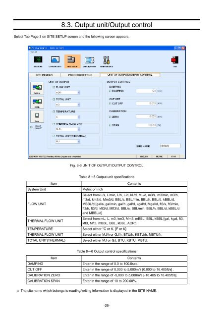
8.3. Output unit/Output control Select Tab Page 3 on SITE SETUP screen and the following screen appears. Fig. 8-6 UNIT OF OUTPUT/OUTPUT CONTROL System Unit FLOW UNIT Item Table 8-5 Output unit specifications Metric or inch Contents Select from L/s, L/min, L/h, L/d, kL/d, ML/d, m3/s, m3/min, m3/h, m3/d, km3/d, Mm3/d, BBL/s, BBL/min, BBL/h, BBL/d, kBBL/d, MBBL/d [gal/s, gal/min, gal/h, gal/d, kgal/d, Mgal/d, ft3/s, ft3/min, ft3/h, ft3/d, kft3/d, Mft3/d, BBL/s, BBL/min, BBL/h, BBL/d, kBBL/d and MBBL/d] THERMAL FLOW UNIT Select from mL, L, m3, km3, Mm3, mBBL, BBL, kBBL [gal, kgal, ft3, kft3, Mft3, mBBL, BBL, kBBL, ACRf] TEMPERATURE Select either °C or K. [F or K] THERMAL FLOW UNIT Select either MJ/h or GJ/h, BTU/h, KBTU/h, MBTU/h. TOTAL UNIT(THERMAL) Select either MJ or GJ, BTU, KBTU, MBTU. Table 8-6 Output control specifications Item Contents DAMPING Enter in the range of 0.0 to 100.0sec. CUT OFF Enter in the range of 0,000 to 5,000m/s [0.000 to 16.405ft/s] . CALIBRATION ZERO Enter in the range of -5,000 to 5,000m/s [-16.405 to 16.405ft/s]. CALIBRATION SPAN Enter in the range of 10 to 200.00%. • The site name which belongs to reading/writing information is displayed in the SITE NAME. -26-
9. Maintenance Click the “MAINTENANCE” button on the Menu screen, and the following screen appears. Fig. 9-1 RECEIVED SIGNAL screen -27-
- Page 1 and 2: Instruction Manual PORTAFLOW C PC L
- Page 3 and 4: 1. OUTLINE 1.1. COPYRIGHT OF THIS S
- Page 5 and 6: (3) There is a query about the Lice
- Page 7 and 8: 2.2. Installing Microsoft .NET Fram
- Page 9 and 10: (5) After installation, the Complet
- Page 11 and 12: 2.4. Device Recognition (1) After t
- Page 13 and 14: Fig. 2-18 Installation confirmation
- Page 15 and 16: (3) There is a query about selectio
- Page 17 and 18: 3. Communication Specification See
- Page 19 and 20: 4.1. Version On the Menu screen, cl
- Page 21 and 22: 6. Measurement Click the “MEASURE
- Page 23 and 24: 7. Logger data Click the ”Logger
- Page 25 and 26: 8.1. Site Memory Select Tab Page 1
- Page 27: Item SENSOR MOUNT Table 8-3 Sensor
- Page 31 and 32: 9.2. Adjustment of graph scale For
- Page 33 and 34: 10.1. Flow velocity profile Select
- Page 35 and 36: 11. QUIT Click the Quit on the main
- Page 37 and 38: (2) Select the [Ports (COM & LPT)]
- Page 39 and 40: (3) The [Hardware Update Wizard] is
- Page 41 and 42: (8) Now, installation starts. If th
8.3. Output unit/Output control<br />
Select Tab Page 3 on SITE SETUP screen and the following screen appears.<br />
Fig. 8-6 UNIT OF OUTPUT/OUTPUT CONTROL<br />
System Unit<br />
FLOW UNIT<br />
Item<br />
Table 8-5 Output unit specifications<br />
Metric or inch<br />
Contents<br />
Select from L/s, L/min, L/h, L/d, kL/d, ML/d, m3/s, m3/min, m3/h,<br />
m3/d, km3/d, Mm3/d, BBL/s, BBL/min, BBL/h, BBL/d, kBBL/d,<br />
MBBL/d [gal/s, gal/min, gal/h, gal/d, kgal/d, Mgal/d, ft3/s, ft3/min,<br />
ft3/h, ft3/d, kft3/d, Mft3/d, BBL/s, BBL/min, BBL/h, BBL/d, kBBL/d<br />
and MBBL/d]<br />
THERMAL FLOW UNIT<br />
Select from mL, L, m3, km3, Mm3, mBBL, BBL, kBBL [gal, kgal, ft3,<br />
kft3, Mft3, mBBL, BBL, kBBL, ACRf]<br />
TEMPERATURE Select either °C or K. [F or K]<br />
THERMAL FLOW UNIT<br />
Select either MJ/h or GJ/h, BTU/h, KBTU/h, MBTU/h.<br />
TOTAL UNIT(THERMAL)<br />
Select either MJ or GJ, BTU, KBTU, MBTU.<br />
Table 8-6 Output control specifications<br />
Item<br />
Contents<br />
DAMPING<br />
Enter in the range of 0.0 to 100.0sec.<br />
CUT OFF Enter in the range of 0,000 to 5,000m/s [0.000 to 16.405ft/s] .<br />
CALIBRATION ZERO<br />
Enter in the range of -5,000 to 5,000m/s [-16.405 to 16.405ft/s].<br />
CALIBRATION SPAN Enter in the range of 10 to 200.00%.<br />
• The site name which belongs to reading/writing information is displayed in the SITE NAME.<br />
-26-


