PAPERLESS RECORDER
1.1 Paperless recorder
1.1 Paperless recorder

Create successful ePaper yourself
Turn your PDF publications into a flip-book with our unique Google optimized e-Paper software.
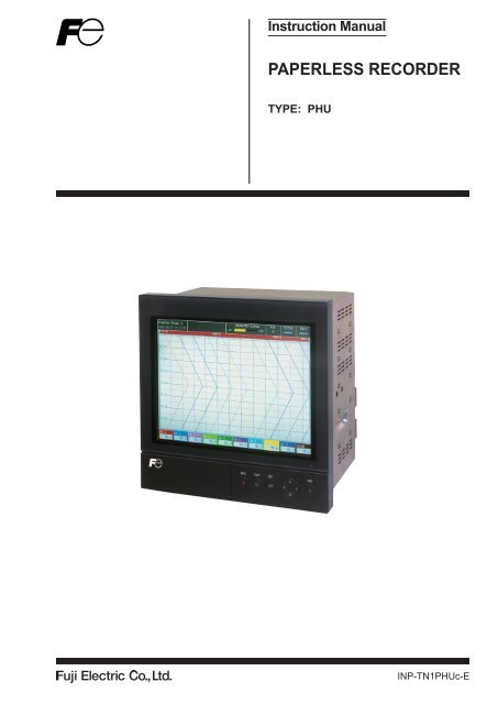
Instruction Manual<br />
<strong>PAPERLESS</strong> <strong>RECORDER</strong><br />
TYPE: PHU<br />
INP-TN1PHUc-E
PREFACE<br />
Thank you for your purchasing Fuji Paperless Recorder (Type: PHU).<br />
• Read this instruction manual carefully to ensure correct installation, operation and preparation.<br />
Incorrect handling may lead to accident or injury.<br />
• Specifications of this unit are subject to change without prior notice for improvement.<br />
• Modification of this unit without permission is strictly prohibited.<br />
Fuji will not be bear any responsibility for a trouble caused by such a modification.<br />
• This instruction manual should be kept by the person who is actually using the unit.<br />
• After reading the manual, be sure to keep it at a place easy to access.<br />
• This instruction manual should be delivered to the end user without fail.<br />
Manufacturer : Fuji Electric Co., Ltd.<br />
Type<br />
: Shown on nameplate of Paperless Recorder<br />
Date of manufacture : Shown on nameplate of Paperless Recorder<br />
Product nationality : Japan<br />
(Note) Windows 2000/XP/7, Excel, WORD PAD are registered trademarks of Microsoft Corporation.<br />
(Note) Compact Flash is a trademark of SanDisk Corporation.<br />
Request<br />
• It is prohibited to transfer part or all of the manual without<br />
Fuji’s permission.<br />
• Description in this manual will be changed without prior<br />
notice.<br />
© Fuji Electric Co., Ltd. 2007<br />
Issued in September, 2007<br />
Rev. 1st edition May, 2008<br />
Rev. 2nd edition April, 2011<br />
Rev. 3rd edition February, 2012<br />
INP-TN1PHU-E<br />
i
CAUTION ON SAFETY<br />
Read this “Caution on Safety” carefully before using the instrument.<br />
• Be sure to observe the instructions shown below, because they describe important information on safety.<br />
The degree of danger is classified into the following two levels: “DANGER” and “CAUTION.”<br />
The signs and their meanings are as follows:<br />
DANGER<br />
Improper handling may cause dangerous situations that may<br />
result in death or severe injury.<br />
CAUTION<br />
Improper handling may cause dangerous situations that may<br />
result in moderate or light injuries or property damage.<br />
DANGER<br />
• When there is a possibility that the abnormality of this instrument may cause a major accident or<br />
damage to other instruments, externally install an adequate emergency stop circuit or a protection<br />
circuit to prevent accidents.<br />
• This product is provided with a built-in fuse that cannot be replaced by the customer. Therefore, we<br />
recommend you to separately provide adequate fuses externally. (Rating: 250V, 2A)<br />
The details of the built-in fuse are as follows.<br />
Type: TR-5 19372, 3.15A (Manufactured by Wickmann-Werke GmbH)<br />
Rating: 250V, 3.15A, Type: T (Slow-blow type)<br />
• Feed the power-supply voltage to specifications to prevent damages to and breakdown of the instrument.<br />
• Never turn on the power before all the mounting and wiring work are finished to prevent electric<br />
shock, malfunction or failure of the instrument.<br />
• Never use this instrument in an environment where flammable or explosive gases exist, since this is<br />
not of intrinsically safe construction.<br />
• Never disassemble, remodel, modify, or repair this instrument. Otherwise malfunction, electric<br />
shock, or failure may result.<br />
• Never touch the terminal while the instrument is being energized. Otherwise electric shock or malfunction<br />
may result.<br />
• Turn off the power before attaching/detaching the module/unit. Otherwise electric shock, malfunction<br />
or failure may result.<br />
• We recommend you to perform periodic maintenance for the safe and continuous use of this instrument,<br />
because consumable parts or those which deteriorate with time are mounted in this instrument.<br />
• Do not block the ventilation holes at the top and the bottom of this instrument. Otherwise a failure,<br />
malfunction, shortened service life, or fire may result.<br />
ii<br />
INP-TN1PHU-E
CAUTION<br />
• Never use the instrument if it is found damaged or deformed when unpacked. Otherwise a fire, malfunction,<br />
or failure may result.<br />
• Check that the instrument is to the proper specifications. Otherwise damage or failure may result.<br />
• Do not give a shock to the instrument by falling or toppling it. Otherwise damage or failure may result.<br />
• Operate the instrument paying attention to prevent foreign matters such as scraps, electric wire chips,<br />
and iron powder from entering in the instrument. Otherwise malfunction or failure may result.<br />
• Check every six months that the terminal screws and mounting screws are securely fastened. Loose<br />
screws may cause fire, malfunction, or failure.<br />
• When changing the setting during the operation or forcibly outputting, starting or stopping the instrument,<br />
be sure to check that safety is ensured. Improper operation may result in damage or failure<br />
of the instrument.<br />
• Be sure to keep the attached terminal cover mounted on the terminal block during the operation.<br />
Otherwise electric shock or fire may result.<br />
• Never install this instrument in the following environments.<br />
A place where the ambient temperature goes beyond the range from 0 to 50°C (0 to 40°C when the<br />
instrument is provided with Ethernet function).<br />
A place where the ambient humidity goes beyond the range from 20 to 80% RH<br />
A place where condensation occurs<br />
A place where corrosive gases (sulfuric gases or ammonia, etc., in particular) or flammable gases<br />
exist<br />
A place where vibration or impact may be applied to the instrument (permissible continuous vibration<br />
condition: 4.9 m/s 2 or lower)<br />
A place subjected to water, oil, chemicals, vapor, or steam<br />
A place subjected to dust and high in salt or iron content<br />
A place where inductive interference may have a great effect, thus causing static electricity, magnetism,<br />
or noises<br />
A place subjected to heat accumulation by radiant heat or the like<br />
If the instrument is installed near other electronics instruments, such as TV in particular, noises may<br />
be caused. Take the following measures in these cases.<br />
• Place the instrument as far from the TV or the radio as possible (1m or more)<br />
• Change the orientation of the antenna of the TV or the radio.<br />
• Use separate receptacles.<br />
• When mounting this instrument against the panel, pay attention not to apply stress to the case. Otherwise<br />
the case may be damaged.<br />
• Stop using the instrument if it is immersed in water. Otherwise electric leak, electric shock, or fire<br />
may result.<br />
• Do not use the wires other than the specified compensation conducting wires for the thermocouple<br />
input connection. Otherwise improper indication or malfunction may result.<br />
• Use a wire material with low wire resistance and with small resistance difference among the three<br />
wires for the resistance bulb input connection. Otherwise improper indication or malfunction may<br />
result.<br />
INP-TN1PHU-E<br />
iii
CAUTION<br />
• If a large noise is generated from the power supply, provide an isolating transformer and use a noise<br />
filter.<br />
• Never use organic solvents such as alcohol or benzene when cleaning this instrument. Do not directly<br />
water the main unit. Otherwise deterioration, failure, electric leak, electric shock, or fire may<br />
result. When cleaning the main unit, wipe with a dry cloth.<br />
• Dispose the instrument as an industrial waste.<br />
• Be sure to ground the instrument. Otherwise electric shock or malfunction may result.<br />
• Only authorized workers should perform wiring. Improper wiring may cause fire, failure, or electric<br />
shock.<br />
• At this equipment, the electrostatic discharge is evaluated as performance criteria B in EN61326.<br />
• This product contains a CR Coin Lithium Battery which contains Perchlorate Material-special handling<br />
may apply. See www.dtsc.ca.gov/hazardouswaste/perchlorate<br />
iv<br />
INP-TN1PHU-E
CONTENTS<br />
PREFACE......................................................................................................................i<br />
CAUTION ON SAFETY .............................................................................................ii<br />
CONTENTS .................................................................................................................v<br />
1. INTRODUCTION .............................................................................................1-1<br />
1.1 Paperless recorder ...............................................................................................1-1<br />
1.2 Product check ......................................................................................................1-1<br />
1.3 Check on type and specification ..........................................................................1-2<br />
1.4 Handling memory card (Compact Flash)– Cautions on handling .......................1-2<br />
1.5 Ethernet communication function .......................................................................1-4<br />
2. NAMES AND FUNCTIONS OF PARTS .........................................................2-1<br />
2.1 Names and functions of parts ..............................................................................2-1<br />
2.2 Inserting and removing the memory card ...........................................................2-3<br />
2.3 Recording data to memory card ..........................................................................2-4<br />
3. MOUNTING METHOD ....................................................................................3-1<br />
3.1 Mounting location ...............................................................................................3-1<br />
3.2 External dimensions and panel cutout dimensions (unit: mm) ...........................3-1<br />
3.3 How to mount the unit onto the panel .................................................................3-2<br />
4. WIRING .............................................................................................................4-1<br />
4.1 Before wiring ......................................................................................................4-1<br />
4.2 Connection to terminals ......................................................................................4-2<br />
4.3 Connecting recorder to loader ...........................................................................4-11<br />
5. DISPLAY FUNCTION .....................................................................................5-1<br />
5.1 Basic composition of Data Display screen .........................................................5-1<br />
5.2 Real time trend display of measured data ...........................................................5-2<br />
5.3 Display of measured data in bar graphs or analog meters ..................................5-4<br />
5.4 Digital display of measured data .........................................................................5-5<br />
5.5 Totalizing data display ........................................................................................5-5<br />
5.6 Event summary display .......................................................................................5-7<br />
5.7 Ethernet log display ............................................................................................5-9<br />
5.8 Historical trend display .....................................................................................5-10<br />
5.9 Display on the occurrence of main unit failure .................................................5-11<br />
5.10 Cautions about power ON/OFF ........................................................................5-12<br />
INP-TN1PHU-E<br />
CAUTION<br />
Refer to chapters 3 and 4 only when installing this instrument. Only qualified<br />
workers should carry out mounting and wiring of this instrument.<br />
v
6. OPERATION AND ACTIONS .........................................................................6-1<br />
6.1 Before running the recorder ................................................................................6-1<br />
6.2 Power ON and state .............................................................................................6-2<br />
6.3 Stopping and starting the recording operation ....................................................6-3<br />
6.4 Switching data display screens ...........................................................................6-5<br />
6.5 Display of alarm .................................................................................................6-6<br />
7. SETTING AND CHECKING PARAMETERS ................................................7-1<br />
7.1 Setting and checking ...........................................................................................7-1<br />
7.2 Outline of parameter setting procedure ...............................................................7-6<br />
7.3 Basic operation of setting screens .....................................................................7-10<br />
8. SETTING PARAMETERS ...............................................................................8-1<br />
8.1 Basic setting ........................................................................................................8-1<br />
8.2 Channel settings ..................................................................................................8-8<br />
8.3 Copying parameters ..........................................................................................8-24<br />
8.4 Setting calculation function ..............................................................................8-26<br />
8.5 Setting timer for calculation ..............................................................................8-32<br />
8.6 Setting for data display screen ..........................................................................8-34<br />
8.7 Setting for F value calculation (Setting common to all channels) ....................8-38<br />
8.8 Setting totalizing (Setting common to all channels) .........................................8-40<br />
8.9 Setting for messages ..........................................................................................8-44<br />
8.10 Unit definition .................................................................................................8-46<br />
8.11 Setting for DI (external control unit) function ................................................8-47<br />
8.12 Setting constant ...............................................................................................8-49<br />
8.13 Ethernet function setting .................................................................................8-50<br />
8.14 Setting password for parameter setting ...........................................................8-53<br />
9. OPERATING MEMORY CARD ......................................................................9-1<br />
9.1 Displaying record data of memory card ..............................................................9-1<br />
9.2 Removing memory card (compact flash) ............................................................9-4<br />
9.3 Totalizing start/stop setting .................................................................................9-6<br />
9.4 Function of reading settings from memory card (compact flash) .......................9-8<br />
9.5 Function of writing settings in memory card (compact flash) ............................9-9<br />
9.6 Setting password for memory card operation ...................................................9-11<br />
10. MAINTENANCE AND INSPECTION ..........................................................10-1<br />
10.1 Recommended replacement cycle of parts ........................................................10-1<br />
10.2 Calibration .........................................................................................................10-1<br />
10.3 Formatting the memory card .............................................................................10-1<br />
10.4 Cleanup method ................................................................................................10-1<br />
vi<br />
INP-TN1PHU-E
11. CALIBRATION ..............................................................................................11-1<br />
11.1 Calibration method of measured values ............................................................11-1<br />
11.2 Initializing the measured value .........................................................................11-3<br />
12. TROUBLESHOOTING ...................................................................................12-1<br />
13. SPECIFICATIONS ..........................................................................................13-1<br />
APPENDICES ..........................................................................................................A-1<br />
Appendix 1 Recording format (ASCII)....................................................................... A-1<br />
Appendix 2 Parameters that cannot be set during recording ........................................A-3<br />
Appendix 3 Parameters that cannot be set while totalizing is underway .................... A-4<br />
Appendix 4 Opening the PHU record data in ASCII format on Excel ....................... A-5<br />
Appendix 5 Timing of recording ................................................................................. A-6<br />
INP-TN1PHU-E<br />
vii
1. INTRODUCTION<br />
We thank you for purchasing Fuji Paperless Recorder PHU.<br />
The instruction manual describes installation, operation, and maintenance of Paperless Recorder.<br />
Read this manual carefully before use.<br />
1.1 Paperless recorder<br />
(1) This recorder displays measured data in real time on the liquid crystal display. It is a paperless<br />
type that is also capable of saving the measured data to a compact flash card.<br />
(2) It can set up to 36 channels for the input types such as thermocouple, resistance bulb, and DC<br />
voltage (or current).<br />
(3) It allows the measured data saved to the compact flash card to be displayed on the display unit.<br />
Use of the support software attached to the recorder allows the saved data to be displayed on a<br />
personal computer.<br />
1.2 Product check<br />
Upon receiving the recorder unit, check the appearance for damage, and if the correct quantity of the<br />
accessories are supplied.<br />
Check on accessories<br />
This recorder comes with the accessories shown in Fig. 1-1. Check that they are all present.<br />
(1) Panel-mounting<br />
bracket<br />
(2) PC support software<br />
(CD-ROM)<br />
(3) Power supply<br />
noise filter<br />
Fig. 1-1 Accessories<br />
Product name<br />
Quantity<br />
(1) Panel-mounting bracket 2<br />
(2) CD-ROM<br />
PC support software instruction<br />
manual<br />
1<br />
(3) Power supply noise fi lter 1<br />
(4) Quick reference 1<br />
INP-TN1PHU-E<br />
1-1
1.3 Check on type and specification<br />
Code symbols are marked on specification nameplates. Check the type as ordered. (The specification<br />
nameplates are attached to the right of the case and at the rear of the display unit).<br />
Digit<br />
4<br />
7<br />
8<br />
9<br />
11<br />
12<br />
Specifications<br />
<br />
9<br />
18<br />
27<br />
36<br />
<br />
Without<br />
With (16 points)<br />
<br />
<br />
English<br />
<br />
Without<br />
Relay 10 points<br />
Relay 20 points<br />
Transistor (open collector) 16 points<br />
Relay 10 points + Transistor (open collector) 16 points<br />
Relay 20 points + Transistor (open collector) 16 points<br />
<br />
Without<br />
With<br />
PHU<br />
Note<br />
4 5 6 7 8 910111213<br />
0 0 1 - 1 Y<br />
* *<br />
E<br />
* *<br />
1<br />
2<br />
3<br />
4<br />
0<br />
1<br />
1<br />
E<br />
0<br />
1<br />
2<br />
3<br />
4<br />
5<br />
Y<br />
E<br />
1.4 Handling memory card (Compact Flash)<br />
– Cautions on handling<br />
(1) For the memory card, use SanDisk’s compact flash memory (URL: http://www.sandisk.com).<br />
Other memory cards may case trouble to the recorder.<br />
CAUTION<br />
1) Be sure to format the memory card with the PC you use.<br />
Format it as FAT16 or FAT. If it is formatted as NTFS, for example, it cannot<br />
be used because the PHU does not recognize it.<br />
2) The memory card should be inserted in the proper direction and fixed securely<br />
to the slot.<br />
3) Don’t turn OFF the power or remove the card from the slot while data is being<br />
written in or read from the card, or recorded data may be damaged or lost.<br />
4) Measured data saved to the memory card should be backed up once a month.<br />
If the CF card should be broken, important record data will be lost. Be sure to<br />
backup the data.<br />
Before using a CF card adaptor, check the capacity of the adaptor. If the capacity<br />
of the memory card to be formatted is larger than that of the adaptor, do<br />
no format the card. Otherwise the PHU does not recognize it even if it could<br />
be formatted on Windows.<br />
1-2 INP-TN1PHU-E
(2) Compact flash in the capacity range from 64MB to 1GB can be used.<br />
Refer to the following tables for the storage capacity in the case of 9-channel recording (on condition<br />
that no events such as alarms or messages are occurring, and that integration is stopped).<br />
(The number of days required for 18-channel recording is approximately one half of those shown<br />
in the table.)<br />
(The number of days required for average value recording and instantaneous value recording is<br />
approximately twice of those shown in the table.)<br />
Compact flash size<br />
Display refresh cycle<br />
Recordable capacity ASCII format<br />
(about)<br />
Binary format<br />
Compact flash size<br />
Display refresh cycle<br />
Recordable capacity ASCII format<br />
(about)<br />
Binary format<br />
64MB<br />
1 sec 10 sec 30 sec 1 min 10 min<br />
112 hours 46 days 140 days 280 days 7.7 years<br />
448 hours 184 days 560 days 1,120 days 30.8 years<br />
128MB<br />
1 sec 10 sec 30 sec 1 min<br />
226 hours 94 days 282 days 565 days<br />
932 hours 388 days 3.2 years 6.4 years<br />
Compact flash size<br />
256MB<br />
Display refresh cycle<br />
1 sec 10 sec 30 sec 1 min<br />
Recordable capacity ASCII format 18 days 187 days 1.5 years 3 years<br />
(about)<br />
Binary format 72 days 748 days 6 years 12 years<br />
Note: Refer to Item 8.1 “Basic setting” for the selection of ASCII or binary format for data recording.<br />
(3) Data write to the memory card is performed according to the following timing. If the power is<br />
OFF in the writing cycle, note that the data will not be recorded.<br />
Display refresh cycle 1 sec to 1min 2 min 3 min 5 min 10 min 20 min 30 min<br />
Write cycle 1 min 2 min 3 min 5 min 10 min 20 min 30 min<br />
Display refresh cycle 1 hour 2 hours 3 hours 4 hours 6 hours<br />
12 hours<br />
Write cycle<br />
1 hour 2 hours 3 hours 4 hours 6 hours 12 hours<br />
(4) The data recorded in the compact flash can be regenerated on the PC by using the data viewer<br />
(contained in the attached CD-ROM).<br />
If the data is recorded in ASCII format, it can be directly opened in a spreadsheet such as EXCEL.<br />
However, large-amount data cannot be opened (about 10MB or larger in the case of 9-point input,<br />
and about 5MB or larger in the case of 18-point input).<br />
In those cases, read in data with the data viewer (contained in the attached CD-ROM), and perform<br />
CSV conversion to divide the file, which allows the data to be read in.<br />
The data recorded in binary format cannot be directly opened in a spreadsheet such as EXCEL.<br />
Refer to Item 8.1 “Basic setting” for details.<br />
Note: Be careful not to make the size of a file too large even if a large-capacity CF card is<br />
used. (Keep it to less than 10MB if possible.)<br />
INP-TN1PHU-E<br />
1-3
(5) Removing memory card<br />
By prohibiting the writing on the memory card, the card can be taken out even if the recording or<br />
integration is not stopped. Refer to Item 9.2 “Removing memory card (compact flash)” for the<br />
procedure.<br />
Make sure to prohibit writing before removing the memory card, when using FTP<br />
CAUTION<br />
server function.<br />
1.5 Ethernet communication function<br />
By connecting the paperless recorder to Ethernet, the following function can be used (when E is<br />
selected for the 12th digit of the code symbols).<br />
• FTP server function: Record files stored in the compact flash of the recorder can be downloaded<br />
from the PC on the network using Web browser (Microsoft Internet Explorer) or DOS prompt.<br />
• Web server function: Measurements of the recorder or event log on the network can be displayed<br />
using Web browser (Microsoft Internet Explorer).<br />
• E-mail function: E-mails can be sent to specified addresses on occurrence of an alarm or main unit<br />
failure.<br />
• MODBUS TCP/IP function: Settings of the recorder can be read or written via the Ethernet.<br />
Ethernet<br />
1-4 INP-TN1PHU-E
2. NAMES AND FUNCTIONS OF PARTS<br />
2.1 Names and functions of parts<br />
(1) Display unit<br />
(2) Power switch<br />
(7) Status display lamp<br />
(3) Memory<br />
(6) Function keyboard<br />
card slot<br />
INP-TN1PHU-E<br />
(1) Display unit<br />
2-1<br />
(4) Memory card<br />
ejection button<br />
(5) Connector to<br />
parameter loader<br />
Allows the Real time trend screen, Bar Graph Display screen, Analog Meter Display screen,<br />
Digital Display screen, Totalized Value Display screen, Historical trend screen and other various<br />
Parameter Set screens to be displayed.<br />
(2) Power switch<br />
Used to turn the power ON or OFF.<br />
(3) Memory card slot<br />
Used for inserting the memory card<br />
(4) Memory card ejection button<br />
To remove the memory card from the slot, press this button.<br />
1) Do not remove the memory card while recording is in progress (while the REC<br />
CAUTION lamp on the display unit is highlighted) or during totalizing. Otherwise, the data<br />
cannot be recorded correctly, besides the past data may be damaged. Be sure to<br />
stop recording and totalizing before removing the memory card. (If the memory<br />
card is removed and inserted again while recording or totalizing is in progress, it<br />
is recorded as a new file.)<br />
2) While the compact flash of the paperless recorder is accessed by FTP communication,<br />
do not take out the compact flash.<br />
Furthermore, when the FTP server function is used, inhibit access to the compact<br />
flash in the “Memory card abstract” screen shown in “9.2 Removing<br />
memory card (compact flash)”, before taking out the compact flash.<br />
(5) Connector to parameter loader<br />
When changing parameters by using a loader, connect the exclusive cable (optional cable:<br />
PHZP1801) to the connector.<br />
(6) Function keyboard<br />
Used for operation, or setting and verifying each parameter.<br />
(7) Status display lamp<br />
Displays power ON/OFF, LCD (screen) ON/OFF, and the recording status.<br />
Lamp ON : Power : ON, LCD : ON (recording/recording stop)<br />
Lamp blinking (ON/OFF for 2 sec) : Power : ON, LCD : OFF (recording)<br />
Lamp blinking (ON/OFF for 1 sec) : Power : ON, LCD : OFF (recording stop)<br />
Lamp OFF : Power : OFF
Key operation<br />
(1) (2) (3) (5) (4)<br />
Key name<br />
Function<br />
(1)<br />
(2)<br />
(Record)<br />
Used to start or stop recording.<br />
Pressing once starts recording, and pressing once again stops recording.<br />
Used to switch displayed contents. Every time it is pressed, the display is switched<br />
in the following order: (1) (2) (3) (4) (5) (6) (7) and back to (1).<br />
(3)<br />
(4)<br />
(5)<br />
(Display)<br />
(Select)<br />
(Entry)<br />
(Cursor)<br />
(1) Real time trend display<br />
Displays the measurement data of an arbitrary channel<br />
(2) Key guidance display<br />
Displays the guide for key operation.<br />
(3) Bar graph/analog meter display<br />
Displays the measured data of the channel in a bar graph (or analog meter)<br />
(4) Digital display<br />
Displays the measured data of the channel in numerical values.<br />
(5) Totalizing data display<br />
Displays the totalizing data of an arbitrary channel in numerical values.<br />
(6) Event summary display<br />
Displays the alarm summary or message summary.<br />
(7) Ethernet log display<br />
Displays the FTP communication and E-mail sending log.<br />
Used to switch the parameter setting screen to the data display screen.<br />
Used to switch from the data display screen to the parameter setting screen.<br />
Pressing the key on the parameter setting screen switches to the screen one step up.<br />
Note, however, that pressing the key on the menu screen does not change screens.<br />
(1) Used for selection on the setting screen or registration of the set data.<br />
(2) If the key is pressed while the scales are displayed on the real time trend display screen,<br />
historical trend display screen (*1), or recorded data display screen, the channels for which<br />
scales are to be displayed can be switched.<br />
(Scale of ch1 scale of ch2 ….. scale of ch9 scale of ch1 scale of ch2…..)<br />
*1: The screen in the past of the data currently recorded<br />
(1) Used to select setting items.<br />
(2) Used to increase or decrease numerical values.<br />
(3) Pressing the key on the real time trend displays the historical trend screen (*1).<br />
At this time, the window can be scrolled using the cursor key.<br />
(4) Pressing the or the key on the real time trend display, bar graph/analog meter display,<br />
digital display, or totalized value display screen switches group screens as follows.<br />
key: Group 1 2 3 4 5 6 7 8 1 ...<br />
key: Group ... 1 8 7 6 5 4 3 2 1<br />
*1: The screen in the past of the data currently recorded<br />
2-2 INP-TN1PHU-E
2.2 Inserting and removing the memory card<br />
The memory card is used for saving measured data. Before attempting to use the recorder, set it in the<br />
recorder slot securely.<br />
This section explains how to insert the memory card into or remove it from the slot.<br />
(1) To insert memory card<br />
Step 1) Open the panel unit.<br />
Step 2) Insert the memory card into the slot at the<br />
right side of the panel unit as shown in the<br />
photo.<br />
Insert the card straight into the<br />
slot as shown in the photo at<br />
right.<br />
Be careful not to forcibly press<br />
the card if it is inserted obliquely.<br />
Otherwise the pin on the PHU<br />
may be damaged.<br />
CAUTION<br />
(2) To remove memory card<br />
Step 1) Press the memory card ejection button to<br />
remove the memory card from the slot.<br />
(1) Do not remove the memory<br />
card while data is written in it<br />
(while the lamp indicating writing<br />
status is kept on). Refer to<br />
Item 9.2 “Removing memory<br />
card (compact flash)” for the<br />
removal of the memory card<br />
while recording is in progress.<br />
Memory card ejection button<br />
(2) After inserting the memory<br />
card into the slot, don’t remove<br />
the card before the recorder acknowledge it.<br />
(3) Be careful with static electricity when removing the memory card.<br />
CAUTION<br />
INP-TN1PHU-E<br />
2-3
2.3 Recording data to memory card<br />
(1) Folder configuration of Memory card:<br />
For memory card, the following folder will be created.<br />
Root<br />
Folder<br />
Folder name<br />
S000000<br />
S******.FDT<br />
A******.FDT<br />
Record file<br />
Event file<br />
Folder name File name<br />
T000000 T******.FDT Periodic totalize data file<br />
D******.FDT Daily totalize data file<br />
W******.FDT Weekly totalize data file<br />
M******.FDT Monthly totalize data file<br />
Y******.FDT Yearly totalize data file<br />
R******.FDT Daily (time) totalize data file<br />
E******.FDT External signal totalize data file<br />
Folder name<br />
PARAM PA00000.PHU Setting value<br />
(2) Recorded data:<br />
Data can be recorded in the following three formats. Either ASCII or binary format can be selected<br />
for recording. Refer to Item 8.1 “Basic Setting.”<br />
Trend data : Records the maximum and the minimum values, average value or instantaneous<br />
values of the measured value sampled at display update cycles.<br />
Trend data file name to be created: S00****.FDT (**** is substituted by<br />
four-digit numerical value.)<br />
Refer to “Appendix 1 (1) Trend data file” for recording format.<br />
Event data : Records the information on occurrence or release of alarms and message<br />
issuing information.<br />
Event data file name to be created: A00****.FDT (**** is substituted by<br />
four-digit numerical value.)<br />
Refer to “Appendix 1 (2) Event data file” for recording format.<br />
Totalizing data: Records the totalizing data every totalize recording cycle.<br />
Totalizing data file name to be created as shown below.<br />
Periodic : T000000.FDT<br />
Dairy : D000000.FDT<br />
Weekly : W000000.FDT<br />
Monthly : M000000.FDT<br />
Annual : Y000000.FDT<br />
Dairy (Time set) : R000000.FDT<br />
External : E000000.FDT<br />
(3) Parameter save data:<br />
Setting file: Stores the setting created on the recorder main unit or the parameter loader.<br />
Name of setting file: PA00000.PHU<br />
2-4 INP-TN1PHU-E
(4) Recording capacity:<br />
It depends on the capacity of the memory card.<br />
Refer to the following tables for the storage capacity in the case of 9-channel recording (on condition<br />
that no events such as alarms or messages are occurring, and that totalizing is stopped).<br />
• Maximum number of days to be recorded varies depending on a number of channel. The value of<br />
each channel in comparison with those in the table are as follows:<br />
18-channel: approximately half; 27-channel: approximately one-third;<br />
36 channel: approximately one-fourth.<br />
• The number of days required for average value recording and instantaneous value recording is approximately<br />
twice of those shown in the table.<br />
Compact flash size<br />
Display refresh cycle<br />
Recordable capacity ASCII format<br />
(about)<br />
Binary format<br />
Compact flash size<br />
Display refresh cycle<br />
Recordable capacity ASCII format<br />
(about)<br />
Binary format<br />
64MB<br />
1 sec 10 sec 30 sec 1 min 10 min<br />
112 hours 46 days 140 days 280 days 7.7 years<br />
448 hours 184 days 560 days 1,120 days 30.8 years<br />
128MB<br />
1 sec 10 sec 30 sec 1 min<br />
226 hours 94 days 282 days 565 days<br />
932 hours 388 days 3.2 years 6.4 years<br />
Compact flash size<br />
256MB<br />
Display refresh cycle<br />
1 sec 10 sec 30 sec 1 min<br />
Recordable capacity ASCII format 18 days 187 days 1.5 years 3 years<br />
(about)<br />
Binary format 72 days 748 days 6 years 12 years<br />
Note: Refer to Item 8.1 “Basic setting” for the selection of ASCII or binary format for data recording.<br />
(5) Recording cycle:<br />
Refer to the following tables for the timing of writing the trend data to the compact flash.<br />
The event data is written in the compact flash by the minute.<br />
Display reflesh cycle 1 sec to 1min 2 min 3 min 5 min 10 min 20 min 30 min<br />
Writing cycle 1 min 2 min 3 min 5 min 10 min 20 min 30 min<br />
Display reflesh cycle 1 hour 2 hours 3 hours 4 hours 6 hours<br />
12 hours<br />
Writing cycle<br />
1 hour 2 hours 3 hours 4 hours 6 hours 12 hours<br />
(6) Timing to start recording:<br />
The event data cannot be written in the compact flash until the first display refreshment cycle<br />
passes by.<br />
INP-TN1PHU-E<br />
2-5
3. MOUNTING METHOD<br />
This unit is designed to be panel mounted.<br />
3.1 Mounting location<br />
Select the following location for mounting the unit.<br />
(1) A place that is not subject to vibration or shock.<br />
(2) A place where there is no dust, dirt or corrosive gas.<br />
(3) A place where ambient temperature falls within 0 to 50°C range with minimum temperature fluctuation<br />
(Recorder provided with Ethernet function: 0 to 40°C).<br />
(4) A place that is not struck directly by strong radiant heat.<br />
(5) A place that is free from water drip or dew condensation in the range of 20 to 80%RH.<br />
(6) A place that is well ventilated for the dispersion of heat generated from other devices.<br />
(7) A space that is accessible for wiring, and maintenance and check.<br />
(8) A place that is not affected by electromagnetic wave from wireless machine or<br />
portable telephones.<br />
(9) Mount the unit horizontally, with no tilt to the left or right (The forward tilt ∠α<br />
should be 0° but the unit may be inclined 0 to 30° rearwards.<br />
∠α = 60 to 90°<br />
3.2 External dimensions and panel cutout dimensions<br />
External dimensions<br />
Panel<br />
220.5<br />
(unit: mm)<br />
300<br />
26<br />
175<br />
PUSH<br />
360 MIN<br />
281 +2 0<br />
320 MIN<br />
281 +2 0<br />
300<br />
280<br />
Panel cutout dimensions<br />
2 ≤ t ≤ 26<br />
t<br />
Mounting fixture<br />
INP-TN1PHU-E<br />
3-1
3.3 How to mount the unit onto the panel<br />
Panel<br />
Mounting bracket<br />
• Using the supplied mounting bracket, tighten the upper and lower screws unit the panel to be fixed.<br />
• The panel to be used should be 2 mm or more in thickness.<br />
• This equipment is the panel-mount type. The panel-mount type is the equipment that is designed<br />
based on that the equipment is set on control panels etc. for accident prevention, such as, electric<br />
shock caused by contact to products. In other words, there are possibilities to occur accidents including<br />
electric shock unless setting it on a control panel etc. (For example, inserting a wire etc. to the<br />
cooling slit on the product's main body.)<br />
This equipment should be set on the metallic case if only to control the electromagnetic interference<br />
(EMI) from products. The structure of metallic cases should be the one that the electromagnetic<br />
interference does not leak outside.<br />
• LAN cable should be stored in the metallic duct and wiring in it.<br />
CAUTION<br />
Excessive torque may result in damage to front panel frame or case deformation.<br />
Torque: 0.2 N·m<br />
3-2 INP-TN1PHU-E
4. WIRING<br />
4.1 Before wiring<br />
(Note) When cables are connected to terminals of the recorder unit, do not apply pulling force to them<br />
excessively. Excessive force to the terminal may result in damage to the terminal or cable.<br />
(1) Use the power cable that has the performance equivalent to or higher than 600-V vinyl insulated<br />
power cable (IEC227-3). Install the attached noise filter within approximately 20cm from the<br />
power terminal of this instrument. (Wind the power cable 1 to 2 turns.)<br />
(2) For the thermocouple input, be sure to use a compensated lead wire.<br />
(3) Input signal cables should be wired separately as far as possible (30 cm or more) from power lines<br />
and high-voltage lines to minimize the effect of inductive noise. Shielded cables should preferably<br />
be used. In this case, the shield braids should be earthed at one point.<br />
(4) Up to 2 solderless terminals should be used when connecting cables to terminals. (Be sure to use<br />
an insulation cap.)<br />
(Note)<br />
1) At the completion of wiring of the input terminals, be sure to close the rear cover to ensure<br />
the compensation of reference contact when thermocouple input is used.<br />
In case of thermocouple input, follow the steps to stabilize temperature at the terminal.<br />
• Be sure to attach input terminal cover.<br />
• Don’t use a thick cable to prevent the effect of radiation. It is recommended that the cable<br />
with a diameter of 0.5 mm or less should be used.<br />
• Don’t mount other instruments near a fan to keep temperature stable.<br />
2) Connection of wiring to the external terminals, exclusive use of ring crimp lugs with proper<br />
insulating sleeve.<br />
For power terminals and earth terminals, be sure to use crimp style terminals for M4 screw.<br />
For other terminals, be sure to use crimp style terminals for M3 screw.<br />
3) This unit has no power fuse. Mount a power fuse outside the unit<br />
as required.<br />
Recommended fuse rating: 250V AC, 2A<br />
4) Do not loosen screws that are secured to the terminal case and<br />
power terminal.<br />
INP-TN1PHU-E<br />
4-1
4.2 Connection to terminals<br />
(1) Input terminal<br />
⇒ Connect signal cable for each channel.<br />
(2) Alarm output relay terminal -1<br />
⇒ Connect Alarm relay output (DO1 to 10).<br />
(3) Alarm output relay terminal -2<br />
⇒ Connect Alarm relay output (DO11 to 20).<br />
(4) Alarm output transistor terminal<br />
⇒ Connect Alarm transistor output (DO21 to 36).<br />
(5) DI input terminal<br />
⇒ Connect DI signal input (DI1 to 16).<br />
(6) Power terminal<br />
⇒ Connect power cables to L N terminal.<br />
Power source to be connected should be free from noise.<br />
(7) Ground terminal<br />
⇒ Connect to terminal (Class-D, 100Ω or less).<br />
(8) Ethernet terminal<br />
⇒ Plug in the LAN cable for Ethernet communication.<br />
(8)<br />
(2)<br />
(6)<br />
(7)<br />
(3)<br />
(4)<br />
(5)<br />
(1)<br />
(1)<br />
Do not loosen the screws Do not loosen the screws Do not loosen the screws<br />
Note: Do not loosen the screws. Otherwise accurate measurement may not be carried out with<br />
thermo-couple input.<br />
4-2 INP-TN1PHU-E
(1) Wiring of input terminal<br />
1) Input terminal No. is determined for each channel.<br />
2) When changing the type of input signal (see Item 8.2) after purchasing the unit, connect input<br />
terminals according to the relation between terminal No. and channel No..<br />
Do not apply excessive voltage. Otherwise the PHU circuit may be damaged,<br />
CAUTION and proper operation may not be performed.<br />
Channel 1 to 9<br />
Voltage<br />
Input terminal<br />
CH1 CH2 CH3 CH4 CH5<br />
Thermocouple<br />
Resistance<br />
bulb<br />
1<br />
2<br />
3<br />
4<br />
5<br />
6 7 8 9<br />
10<br />
11<br />
12<br />
13 14<br />
15<br />
16<br />
17<br />
18<br />
19 20<br />
21<br />
22 23<br />
24<br />
25 26<br />
27<br />
Resistance<br />
bulb<br />
Thermocouple<br />
RCJ<br />
Voltage<br />
CH6<br />
CH7<br />
CH8<br />
CH9<br />
Note) For current input, connect optional shunt resitors to the voltage input terminals.<br />
CH1<br />
CH2<br />
CH3 CH4 CH5<br />
Voltage<br />
Thermocouple<br />
Resistance<br />
bulb<br />
Resistance<br />
bulb<br />
RCJ<br />
Thermocouple<br />
Voltage<br />
CH6<br />
CH7<br />
CH8<br />
CH9<br />
INP-TN1PHU-E<br />
4-3
Channel 10 to 18<br />
Input terminal<br />
Voltage<br />
CH10 CH11 CH12 CH13 CH14<br />
Thermocouple<br />
Resistance<br />
bulb<br />
28<br />
29<br />
30<br />
31 32<br />
33 34 35 36<br />
37 38<br />
39<br />
40 41<br />
42<br />
43<br />
44<br />
45<br />
46 47<br />
48<br />
49 50<br />
51<br />
52 53<br />
54<br />
Resistance<br />
bulb<br />
Thermocouple<br />
RCJ<br />
Voltage<br />
CH15<br />
CH16<br />
CH17<br />
CH18<br />
Note) For current input, connect optional shunt resitors to the voltage input terminals.<br />
CH10<br />
CH11<br />
CH12 CH13 CH14<br />
Voltage<br />
Thermocouple<br />
Resistance<br />
bulb<br />
Resistance<br />
bulb<br />
RCJ<br />
Thermocouple<br />
Voltage<br />
CH15<br />
CH16<br />
CH17<br />
CH18<br />
4-4 INP-TN1PHU-E
Channel 19 to 27<br />
Input terminal<br />
Voltage<br />
CH19 CH20 CH21 CH22 CH23<br />
Thermocouple<br />
Resistance<br />
bulb<br />
55<br />
56<br />
57<br />
58 59<br />
60 61 62 63<br />
64 65<br />
66<br />
67 68<br />
69<br />
70<br />
71<br />
72<br />
73 74<br />
75<br />
76 77<br />
78<br />
79 80<br />
81<br />
Resistance<br />
bulb<br />
Thermocouple<br />
RCJ<br />
Voltage<br />
CH24<br />
CH25<br />
CH26<br />
CH27<br />
Note) For current input, connect optional shunt resitors to the voltage input terminals.<br />
CH19<br />
CH20<br />
CH21 CH22 CH23<br />
Voltage<br />
Thermocouple<br />
Resistance<br />
bulb<br />
Resistance<br />
bulb<br />
RCJ<br />
Thermocouple<br />
Voltage<br />
CH24<br />
CH25<br />
CH26<br />
CH27<br />
INP-TN1PHU-E<br />
4-5
Channel 28 to 36<br />
Input terminal<br />
Voltage<br />
CH28 CH29 CH30 CH31 CH32<br />
Thermocouple<br />
Resistance<br />
bulb<br />
82<br />
83<br />
84<br />
85 86<br />
87 88 89 90<br />
91 92<br />
93<br />
94 95<br />
96<br />
97<br />
98<br />
99 100101102<br />
103104105106107108<br />
Resistance<br />
bulb<br />
Thermocouple<br />
RCJ<br />
Voltage<br />
CH33<br />
CH34<br />
CH35<br />
CH36<br />
Note) For current input, connect optional shunt resitors to the voltage input terminals.<br />
CH28<br />
CH29<br />
CH30 CH31 CH32<br />
Voltage<br />
Thermocouple<br />
Resistance<br />
bulb<br />
Resistance<br />
bulb<br />
RCJ<br />
Thermocouple<br />
Voltage<br />
CH33<br />
CH34<br />
CH35<br />
CH36<br />
4-6 INP-TN1PHU-E
Wiring of input terminals (For an example, ch1 terminal number is noted in the parentheses)<br />
(1) DC voltage input<br />
(2) DC current input<br />
(1) (2) (3) Not used<br />
(1) (2) (3)<br />
Not used<br />
DC current input<br />
Shunt resistor (option)<br />
DC voltage input<br />
Example 1)<br />
For 4 to 20mA and 10 to 50mA input,<br />
10Ω±0.1% shunt resistance is used.<br />
In this case, set the input range<br />
to 500mV (see Item 8.2).<br />
(3) Themocouple input<br />
(4) Resistance input<br />
(1) (2) (3) (1) (2) (3)<br />
Voltage conversion by shunt resistance of 10Ω<br />
4 to 20mA DC : 40 to 200mV DC<br />
10 to 50mA DC : 100 to 500mV DC<br />
Not used<br />
b B A<br />
Compensating<br />
leads<br />
Thermocouple<br />
Red(A)<br />
White(B)<br />
White(b)<br />
Note) Avoid using thermocouple input with wiring<br />
parallel to other instruments.<br />
Resistance bulb<br />
Note)<br />
1) Input signals should be the same for every 2 channels.<br />
Example) ch1: thermocouple<br />
Any type of thermocouple can be set.<br />
ch2: thermocouple<br />
ch3: 5V<br />
1 to 5V or 0 to 5V can be set.<br />
ch4: 5V<br />
For the setting method, see Item 7.4.<br />
2) Do not remove RCJ module.<br />
INP-TN1PHU-E<br />
4-7
(2) Wiring of alarm output (DO)/DI (external control unit) (Option)<br />
About external control unit (DI)<br />
1) This instrument is provided with the function of performing “start/stop of recording operation,”<br />
“F-value computation resetting,” “Start/stop of totalizing,” and “Message display” in response to<br />
the contact signals (DI) received from outside the instrument.<br />
DI1 DI2 DI3 DI4 DI5 DI6 DI7 DI8<br />
DI input terminal<br />
DI 0V<br />
61<br />
DI1<br />
62<br />
71<br />
DI2<br />
63<br />
DI3<br />
64<br />
DI4<br />
65<br />
DI5<br />
66<br />
DI6<br />
67<br />
DI7<br />
68<br />
DI8<br />
69<br />
DI9 DI10 DI11 DI12 DI13 DI14 DI15 DI16<br />
72<br />
73<br />
74<br />
75<br />
76<br />
77<br />
78<br />
DI 0V<br />
70<br />
79<br />
80<br />
DI9 DI10 DI11 DI12 DI13 DI14 DI15 DI16<br />
Note 1) DI (external control) unit is not insulated and should be used with a relay connected to<br />
the outside.<br />
External contact capacity: 20V/0.05A DC, 1a contact or larger<br />
Note 2) DI (external control) unit is operated as follows when the front switch is pressed.<br />
(1) Recording start/stop<br />
(2) F value calculation reset<br />
External control<br />
Front key<br />
External control<br />
Recording<br />
suspended<br />
Recording start/stop by DI<br />
ON<br />
Starts recording<br />
OFF<br />
No change<br />
Starts recording<br />
F value<br />
calculation<br />
in progress<br />
ON<br />
Resets F value.<br />
OFF<br />
Continues<br />
calculation.<br />
Recording<br />
in progress<br />
No change<br />
Stops recording<br />
Stops recording<br />
(3) Totalizing reset<br />
(4) Totalizing start/stop<br />
External control<br />
External control<br />
ON<br />
OFF<br />
ON<br />
OFF<br />
Totalizing<br />
in progress<br />
Resets<br />
totalized value.<br />
Continues totalizing.<br />
Totalizing<br />
suspended<br />
Starts totalizing<br />
Totalizing<br />
in progress<br />
Stops totalizing<br />
(5) LCD<br />
ON<br />
External control<br />
OFF<br />
LCD OFF<br />
LCD ON<br />
4-8 INP-TN1PHU-E
About alarm output (relay)<br />
1) Alarm setting is provided at 4 points for each input channel. Up to 20 points for alarm output<br />
relay can be set as an option.<br />
2) When an alarm occurs, the relevant terminals are shorted (ON).<br />
1a contact output: Relay contact capacity : 240V AC/3A, 30V DC/3A (resistive load)<br />
Alarm output (relay) −1<br />
DO1 DO2 DO3 DO4 DO5 DO6 DO7 DO8 DO9 DO10<br />
M3 screw<br />
DO1<br />
1<br />
DO2<br />
2<br />
DO3<br />
3<br />
DO4<br />
4<br />
DO5<br />
5<br />
DO6<br />
6<br />
DO7<br />
7<br />
DO8<br />
8<br />
DO9<br />
9<br />
DO10<br />
10<br />
11<br />
12<br />
13<br />
14<br />
15<br />
16<br />
17<br />
18<br />
19<br />
20<br />
Alarm output (relay) −2<br />
DO11 DO12 DO13 DO14 DO15 DO16 DO17 DO18 DO19 DO20<br />
M3 screw<br />
DO11<br />
21<br />
DO12<br />
22<br />
DO13<br />
23<br />
DO14<br />
24<br />
DO15<br />
25<br />
DO16<br />
26<br />
DO17<br />
27<br />
DO18<br />
28<br />
DO19<br />
29<br />
DO20<br />
30<br />
31<br />
32<br />
33<br />
34<br />
35<br />
36<br />
37<br />
38<br />
39<br />
40<br />
Note: If lamps are provided on the outside, set a resistor to prevent rush current.<br />
When relays or solenoids are used, set elements for contact protection (diodes or surge<br />
killers, etc).<br />
INP-TN1PHU-E<br />
4-9
About alarm output (transistor)<br />
1) Alarm setting is provided at 4 points for each input channel. Up to 16 points for alarm output<br />
(transistor) can be set as an option.<br />
2) On occurrence of an alarm, the internal transistor is turned ON.<br />
24V DC<br />
Output : Open collector<br />
Rating : 30V DC/0.1A (resistive load)<br />
DO21 DO22 DO23 DO24 DO25 DO26 DO27 DO28<br />
Alarm output (taransister teminal)<br />
M3 screw<br />
VPD DO21 DO22 DO23 DO24 DO25 DO26 DO27 DO28 PCD<br />
41 42 43 44 45 46 47 48 49 50<br />
24V DC+ DO29 DO30 DO31 DO32 DO33 DO34 DO35 DO36 0V<br />
51 52 53 54 55 56 57 58 59 60<br />
Note: This is not relay out.<br />
Do not apply voltage or feed<br />
current larger than the rating.<br />
Otherwise the internal circuit<br />
may be damaged, and the instrument<br />
stops operating.<br />
DO29 DO30 DO31 DO32 DO33 DO34 DO35 DO36<br />
(3) Ethernet (option)<br />
Note: Select E for the 12th digit of code symbols to use this option.<br />
Ethernet communiction specifications are as follows.<br />
Note: Install the LAN cable far away from the power supply line or strong electric line as possible<br />
to avoid the influence of induction noise.<br />
Item<br />
Communication speed<br />
Communication mode<br />
Maximum network length or<br />
Maximum node spacing<br />
Maximum segment length<br />
Connection cable<br />
Communication protocol<br />
Specifications 10BASE-T<br />
10 Mbps<br />
Base band<br />
Up to 500 m (4-stage cascade)<br />
Up to 100 m (between node and HUB)<br />
UTP (Unshielded twisted pair cable) 22-26AWG<br />
TCP/IP<br />
(4) Cautions on connection of input signals via barrier<br />
1) When thermocouple or resistance bulb is used for input:<br />
Measurement value error is generated because resistance value within the barrier is added.<br />
Calibrate the measurement value in a state where the input, barrier, and the recorder are connected.<br />
See section 9.1 for details of calibration.<br />
2) Use our Zener barrier (PWZ) with 100V AC series power supply (85 to 150V AC) according the<br />
restrictions placed to maintain safety ratings.<br />
4-10 INP-TN1PHU-E
4.3 Connecting recorder to loader<br />
(1) When connecting the recorder to a loader, use optional PC loader communication cable<br />
(PHZP1801) as shown below.<br />
(USB cable)<br />
The loader cable should be connected to the USB port of PC.<br />
CAUTION<br />
Be sure to display the data display screen (refer to Item 6.4) instead of the parameter<br />
setting screen before using the loader. Otherwise, the set value may not be<br />
written.<br />
INP-TN1PHU-E<br />
4-11
5. DISPLAY FUNCTION<br />
5.1 Basic composition of Data Display screen<br />
(6) Memory card (7) Memory card (5) Memory card (3) Parameter memory<br />
loading display indicator writing status display lamp (10) Totalizing indicator<br />
(9) Alarm display<br />
(1) Name of<br />
screen<br />
(4) Record display<br />
(2) Clock<br />
display<br />
(8) Data display<br />
area<br />
(1) Name of screen<br />
Displays the screen name (“Display Name”) that was set arbitrarily.<br />
(2) Clock display<br />
Displays date and time.<br />
(3) Parameter memory lamp<br />
If the lamp blinks in red, it means that parameters are not saved to the flash memory.<br />
Perform the “Recording set values” in the equipment.<br />
(4) Record display<br />
The REC lamp is lit when the measured data is being recorded. On the “Real Time Trend”<br />
screen, data will be displayed only when the recorder is in recording.<br />
(5) Memory card writing status display<br />
Turns ON when measured data is being written in a memory card.<br />
(6) Memory card loading display<br />
It indicates the loading state of the memory card.<br />
Gray display : Shows the state where the memory card is not loaded in the slot.<br />
Green display : Shows the state where the memory card can be pulled out.<br />
Red display : Shows the state where the memory card must not be pulled out.<br />
(7) Memory card indicator<br />
It indicates how much of the memory card has bee used in graphs. At 90%, it turns red. When<br />
the overwrite function of the recording file is set to OFF, the recorder stops recording at 100%.<br />
Replace the memory card before it is used up.<br />
(8) Data display area<br />
It displays measured data in real time trend, bar graph, or digital display on the screen. (See item<br />
5.2 to 5.4.) Measured data are displayed for channel 1 to 9 at factory shipment.<br />
(9) Alarm display<br />
It displays alarm information that occurs at present (channel No. and alarm No.).<br />
If more than 1 alarm occurs, it displays one alarm after another in every 3 seconds.<br />
(10) Totalizing indicator<br />
While totalizing is in progress, the TOTAL lamp is lit. Refer to 5.5 for details of totalizing screen.<br />
INP-TN1PHU-E<br />
5-1
5.2 Real time trend display of measured data<br />
Measured data can be displayed in waveforms. The vertical or horizontal directions can be selected by<br />
setting. By pressing ⊳ or key, four screens with different display contents (scale display and screen<br />
structure contents [group configuration], Tag No. unit display, etc.) can be selected one after another.<br />
Vertical trend<br />
Time<br />
(hour: minute)<br />
(24-hour display) Time scale display<br />
Horizontal trend<br />
Trend display<br />
Display division<br />
Display division<br />
Trend display<br />
Measured value<br />
display of each<br />
channel<br />
(instantaneous<br />
value)<br />
Measured value<br />
display in TAG No.<br />
or the unit is also<br />
available.<br />
Time<br />
(hour: minute)<br />
(24-hour display)<br />
Time scale display<br />
Measured value<br />
display of each<br />
channel<br />
(instantaneous<br />
value)<br />
Correct time may not be displayed<br />
because there may be a case where<br />
all the digits of the time display in<br />
horizontal direction are not displayed<br />
on the trend screen.<br />
*) The screens consist of those selected in “Menu” → “Parameter setting” → “Display setting”.<br />
1) The display unit allows measured data to be displayed in waveforms only when recording. If the<br />
recorded values exceed the limits of 0 % and 100%, they will be displayed at 0% and 100% positions,<br />
respectively. If waveforms of more than 1 channel are displayed at the same position, the<br />
trend lines overlap each other. In this case, color of the channel with the largest number is given<br />
priority over those of other channels. (Example: In the case of ch2 and ch8, the color of ch8 is displayed.)<br />
2) Display refreshment cycles are selectable from parameters of 1 sec to 12 hours. Relations between<br />
the parameter and chart speed are shown in tables below. After the start of the recording,<br />
the initial refreshment cycles will start at the time of 00: 00: 00 when the recording is continued.<br />
(Example) When display refreshment cycles are set to 1 minute, it will start at the next cycle of<br />
m hour: n minute: 0 second.<br />
Display refresh cycle (sec) 1 2 3 5 10 20 30<br />
Chart speed (mm/h) as converted 1296 648 432 260 130 65 43<br />
Display refresh cycle (min) 1 2 3 5 10 20 30<br />
Chart speed (mm/h) as converted 22 11 7.2 4.3 2.2 1.1 0.7<br />
Display refresh cycle (hour) 1 2 3 4 6<br />
Chart speed (mm/h) as converted 0.36 0.18 0.12 0.09 0.06<br />
12<br />
0.03<br />
5-2 INP-TN1PHU-E
3) The Historical Trend screen is displayed by pressing the cursor key () when the Real Time<br />
Trend is displayed. This screen allows currently recorded waveform data to be read from the<br />
memory card, tracing back to the past. To return to the Real Time Trend screen, press the<br />
key.<br />
4) The recorder performs the recording by pressing , and it displays waveforms without inserting<br />
the memory card into the slot. In this case, about 400 data can be displayed in historical trend. To<br />
display the data exceeding 400 items, insert the memory card into the slot before starting the recording.<br />
5) If the power is turned OFF while recording, data written in the memory card will be destroyed.<br />
Be sure to press the key to stop the recording, and then turn OFF the power.<br />
6) If the input signal is burnt out, or over/under range is displayed, the recording line is displayed at<br />
0% or 100% position (at 100% position if the signal is burn-out). Note that, the line is displayed<br />
at the position equivalent to 0.26V for 0-5V input with the input kept open, and at the position<br />
equivalent to 260mV for 0-500mV input with the input kept open.<br />
INP-TN1PHU-E<br />
5-3
5.3 Display of measured data in bar graphs or analog<br />
meters<br />
The measured data can be displayed either in bar graphs or analog meters. The display type can be<br />
selected by referring to Item 7.3 “Basic operation of setting screen,” and Item 8.6 “Setting for data<br />
display screen.”<br />
1. The measured data is displayed in a bar graph.<br />
Scale display<br />
Bar graph display<br />
Measured value<br />
display of each<br />
channel<br />
(instantaneous<br />
value)<br />
2. The measured data is displayed in analog meters.<br />
(1) Setting of display ranging from 0 to 100% is displayed in graphs.<br />
(2) Display refreshment cycles are fixed to 1 sec.<br />
(3) The recorder displays measured data even when it stops recording.<br />
5-4 INP-TN1PHU-E
5.4 Digital display of measured data<br />
Measured data is displayed in numerical values.<br />
Channel No.<br />
TAG name<br />
Unit<br />
Alarm No.<br />
occurred<br />
Display of<br />
measured value<br />
(1) Measured values of each channel are displayed in digital value.<br />
(2) Display refreshment cycles are fixed to 1 sec.<br />
(3) When an alarm occurs, Alarm No. at the channel is displayed in red.<br />
5.5 Totalizing data display<br />
Channel No.<br />
TAG name<br />
Totalized value display<br />
Unit<br />
(1) The value displayed depends on the setting of parameter “Reset operation.”<br />
If ON is selected, the totalized value by totalize base time is displayed.<br />
If OFF is selected, the total value from the start of totalizing is displayed.<br />
(2) Display update cycle is fixed to 1 second.<br />
INP-TN1PHU-E<br />
5-5
(3) The value of totalized data to be recorded depends also on “Reset operation.”<br />
If the setting is ON, totalized value is recorded at every totalize base time.<br />
If the setting is OFF, sum total from the totalize start time is recorded.<br />
Example: The data at the flow rate of 100L/hour is recorded as follows.<br />
Totalize reset<br />
Elapsed time OFF ON<br />
1 hour 100 100<br />
2 hours 200 100<br />
3 hours 300 100<br />
(4) Totalize calculation is not reset even if the power is interrupted.<br />
Upon restoration of the power, totalize calculation resumes starting from the data before the<br />
power interruption.<br />
(If the file in the CF card used before the power interruption is lost at the time of power restoration,<br />
a new file is created. The data during the power interruption is not added.)<br />
(5) While totalize calculation is suspended, totalize data is not displayed. It is not displayed, either,<br />
while totalize calculation is suspended with “Daily (Time set)” or “External” selected as Totalize<br />
type.<br />
(6) The instrument can operate not only as a totalizer but also as a timer or a counter depending on<br />
the setting of “Totalize calculation.”<br />
a) If the setting is Totalizer, totalize function is performed.<br />
b) If the setting is Counter, the number of times of DI ON or alarm ON during the totalize period<br />
is displayed and recorded.<br />
c) If the setting is Timer, the duration of DI ON or alarm ON during the totalize period is displayed<br />
and recorded.<br />
In all of the above cases, time is displayed based on the time set in a parameter, “Totalize base<br />
time,” with all digits to the right of the decimal point discarded.<br />
(7) On totalize 4-channel display screen, totalize start/stop time and the previous totalized value are<br />
displayed.<br />
(8) Totalizing is performed until the maximum value 999,999,999 is reached. Totalizing is not performed<br />
when exceeding that value.<br />
5-6 INP-TN1PHU-E
5.6 Event summary display<br />
Alarm information and message information history can be displayed.<br />
The contents of messages can be displayed as message information.<br />
Page of screen<br />
Message summary<br />
Alarm summary (Alarm OFF)<br />
Alarm summary (Alarm ON)<br />
(1) A maximum of 180 events can be displayed on the screen.<br />
(2) Page scrolling can be performed by pressing ⊳ or key.<br />
(3) When events occur, they are displayed on the screen despite in the recording state. If the recorder<br />
is not in the recording state, events are not recorded in the memory card.<br />
(4) Once displayed, the event is kept displayed until the power is turned off (turning off the power<br />
clears the event buffer).<br />
(5) Press the key to switch between message contents display and message start time display.<br />
The message contents are initially displayed.<br />
(6) How to view the event summary and message summary is as follows:<br />
Example of alarm summary<br />
ALM ON CH3 – 1H<br />
Setting alarm No.<br />
(1 to 4) and alarm<br />
types (H and L)<br />
Example of message display<br />
Channnel No.<br />
(1 to 72)<br />
Alarm (ON/OFF)<br />
Example of message summary<br />
Message NO. 03<br />
Message No. that occurred<br />
Note) Message No. means the message<br />
that is defined by selecting “Parameter<br />
Setting” “Message Setting”.<br />
INP-TN1PHU-E<br />
5-7
(7) Turn OFF/ON the power, and event summary is displayed.<br />
Message is changed according to recording status.<br />
1) When power is turned OFF/ON while recording is suspended<br />
(Not recorded in the event file.)<br />
2) When power is turned OFF/ON while recording is in progress<br />
(Recorded in the event file.)<br />
5-8 INP-TN1PHU-E
5.7 Ethernet log display<br />
The communication items of Ethernet function (FTP, E-mail, and MODBUS TCP/IP) can be displayed.<br />
Communication connection lamp<br />
(1) Up to 180 communication items can be displayed.<br />
(2) Pages can be turned using horizontal cursor key.<br />
(3) The log appears every time communication is carried out irrespective of the recording status.<br />
(4) Once displayed, the contents of communication are kept displayed until the power is set to OFF.<br />
(Communication buffer is cleared when the power is set to OFF.)<br />
(5) Details of the display are as follows.<br />
Communication contents display<br />
• E-mail transmission display (E-mail No. is E-mail trigger No.)<br />
E-mail sent<br />
: “E-mail No.1”<br />
E-mail send error : “E-mail No.1 NG”<br />
• FTP communication display<br />
FTP server log in : “FTP LOGON USER1”<br />
FTP server log off : “FTP LOGOFF USER1”<br />
• MODBUS TCP/IP communication display<br />
Communication start : “MODBUS Start”<br />
Communication stop : “MODBUS Stop”<br />
INP-TN1PHU-E<br />
5-9
5.8 Historical trend display<br />
Pressing the key in the real time trend screen displays the screen shown below, which indicates the<br />
history of data currently recorded.<br />
Time at cursor position<br />
Cursor<br />
Measured value at cursor position of<br />
each channnel(Min and Max values)<br />
(1) It allows the data recorded in the memory card to be displayed. The display can be scrolled by<br />
using the cursor expressed in a white dotted line. The cursor can move vertically the ( or )<br />
key or horizontally the (⊳ or ) key. Min. value or Max. value at the position of the cursor are<br />
displayed at the lower part of the screen.<br />
(2) Recording start/stop cannot be performed on the screen. To do this, switch the “Historical Trend”<br />
screen to “Real Time Trend” screen. However, this “Historical Trend” screen cannot be shifted to<br />
the “Parameter Set” screen. To shift the “Real Time Trend” screen, be sure to press the key.<br />
(3) The data that can be displayed on the historical trend screen is the one currently recorded or the<br />
data held immediately before the recording is stopped. The data that was recorded in the past and<br />
whose recording was then stopped must be displayed on the record data display screen, or reproduced<br />
on the PC using the data viewer.<br />
The following items are displayed on the historical trend screen based not on the setting of the<br />
past recording but on the currently selected values.<br />
• Trend direction<br />
• Number of screen partition<br />
• Trend scale display<br />
• Color bar display selection<br />
5-10 INP-TN1PHU-E
(4) Press the key while the historical trend screen is displayed, and following “Display time setting”<br />
screen appears.<br />
Enter the time of currently recorded data you want to display and press the key.<br />
Then, PHL displays historical trend data at entered day and time.<br />
To display past data, entered day and time appears the bottom of the historical screen. To display<br />
farther data, entered day and time appears the top of this screen.<br />
5.9 Display on the occurrence of main unit failure<br />
(1) Display at CF card memory FULL<br />
If the memory of the CF card becomes full, recording is stopped with the following message displayed<br />
on the trend screen, etc. (totalizing is not suspended). Immediately replace the CF card.<br />
(2) Display at the end of battery life<br />
When battery voltage becomes low, the following message appears on the trend screen, etc.<br />
If the message appears, stop recording and totalize calculation, and ask your dealer for repair. After<br />
the display appears, Fix and repair will be required within 1 month. When you power on again<br />
with dead battery, abnormality of time, the record and the total will be caused.<br />
INP-TN1PHU-E<br />
5-11
5.10 Cautions about power ON/OFF<br />
(1) Recording state and record file<br />
If the power is turned OFF when the recorder is in the recording, data written in the memory card<br />
may be damaged. Be sure to stop recording by pressing key, and then turn OFF the power.<br />
In addition, if the power is OFF with the recorder in the recording, the recorder will start recording<br />
when the power is turned ON again. In this case, data will be recorded as a new file.<br />
(2) Recording set values<br />
After parameters have been set, register the set values by selecting “Basic settng” → “Register<br />
data”, or they will return to the former values when power is turned OFF.<br />
(3) Clock function<br />
The clock is backed up by an internal lithium battery. The battery life is expected to be about 10<br />
years at normal temperature. Although there is no need to set the clock when the power is turned<br />
ON, an error may occur every time the power is turned ON/OFF (about 1 sec per ON/OFF operation).<br />
(4) If the power is turned off due to a power failure and turned on again while recording is in progress,<br />
a message “Power & Rec.ON.” appears at the top of the event file and event display.<br />
(5) If the power is turned off, totalizing resumes when the power is turned on again, beginning from<br />
the value before the power off. Data is recorded in the totalize file used before the power off.<br />
(Note that if the file used before the power off is lost from the CF card, a new file is created and<br />
recording is restarted.)<br />
5-12 INP-TN1PHU-E
6. OPERATION AND ACTIONS<br />
6.1 Before running the recorder<br />
Check the following points before starting operation.<br />
Loading the memory card<br />
(1) Inserting and removing the memory card·············································· See Item 2.2.<br />
Wiring<br />
(1) Input terminals······················································································· See Item 4.2.<br />
(2) Alarm terminals (option)········································································ See Item 4.2.<br />
(3) Power and ground terminals·································································· See Item 4.2.<br />
Conformity of input connection to recording channel<br />
(1) Channel settings····················································································· See Item 8.2.<br />
INP-TN1PHU-E<br />
6-1
6.2 Power ON and state<br />
(1) Open the panel unit. Turn “ON” the power switch at the upper center of the panel unit.<br />
(2) After power ON, the self-check function starts up.<br />
(3) Insert a memory card, and then check with the memory card load indicator that the card can be<br />
used. (It can be used if the memory card load indicator is kept ON in green or red, and it cannot<br />
be used if it is kept flickering.) If the memory card load indicator is kept flickering in red even<br />
if the CF card is inserted, remove the CF card, check the direction of insertion (see Item 2.2) and<br />
insert it securely. If the indicator is still flickering, the CF card may not have been formatted, or<br />
some parts may be defective.<br />
Memory card load indicator<br />
Memory card indicator<br />
(4) Measured data are displayed for each channel.<br />
Measured data for<br />
each channel<br />
* TAG. No. or the unit display is also available according to screen configuration setting.<br />
6-2 INP-TN1PHU-E
6.3 Stopping and starting the recording operation<br />
(1) Recording start<br />
1) To start the recording, press the key. The REC lamp is lighted and measured values are<br />
displayed in waveforms on the data display unit. Also, it starts saving the measured values to the<br />
memory card.<br />
* Recording is performed at the timing described in “Appendix 5 Timing for recording.”<br />
ON<br />
Waveforms of<br />
measured values<br />
Press<br />
2) When the password for stopping and starting the record operation is set, the password setting<br />
screen is displayed as follows. Therefore, make a setting of the password. When the password is<br />
correct, the recording is started.<br />
3) If the CF card is not inserted, the following message appears. Press the or the key to<br />
start recording. Press the key, if recording does not start.<br />
Note: If recording is carried out with the CF card not inserted, data cannot be recorded.<br />
INP-TN1PHU-E<br />
6-3
(2) Recording stop<br />
1) To stop recording, press the key. The following message appears. To stop the recording,<br />
press the key again, and press the key to continue recording.<br />
2) After the stop of the recording, the REC lamp comes off. The trend display on the data display<br />
unit stops. Carry out the recording of all data that have not yet written in the memory card.<br />
OFF<br />
Previously recorded<br />
waveforms<br />
3) When the password for stopping and starting the record operation is set, the password setting<br />
screen is displayed as follows. Therefore, make a setting of the password. When the password is<br />
correct, the recording stop confirmation screen is displayed.<br />
6-4 INP-TN1PHU-E
6.4 Switching data display screens<br />
Data display screens include real time trend screen, bar graph (analog meter) screen, digital screen and<br />
totalizing screen. Every time the key is pressed, the screen switches to another one. To display<br />
the historical trend screen, press the key in the real time trend screen.<br />
Press the or key in the real time trend screen to switch to each group screen.<br />
* If group screens are switched in high speed, the color on the color bar may not be displayed correctly.<br />
Display the screen once again in such cases to restore proper color display.<br />
Refer to Item 8.6 for selection of bar graph/analog meter display.<br />
The structure of the data display screen is as follows.<br />
Group 1 Group 2 Group 8<br />
Real time<br />
trend screen<br />
(Refer to<br />
Item 5.2.)<br />
Key operation<br />
guide display<br />
The key operation procedure<br />
on the data display screen is<br />
displayed at the top of the<br />
real time trend screen.<br />
Historical trend screen<br />
(Refer to Item 5.8.)<br />
(Groups cannot be switched<br />
on this screen.)<br />
Bar graph screen<br />
(Refer to Item 5.3.)<br />
and analog meter<br />
screen (Refer to<br />
Item 5.3.)<br />
Digital screen<br />
(Refer to<br />
Item 5.4.)<br />
INP-TN1PHU-E<br />
Totalizing data display screen<br />
(Refer to Item 5.5.)<br />
Event summary screen<br />
(Refer to Item 5.6.)<br />
6-5<br />
Ethernet log display screen<br />
(Refer to Item 5.7.)
6.5 Display of alarm<br />
(1) Alarms that occurred on the Trend Display, Bar Graph and Digital Display<br />
screens:<br />
When an alarm occurs, its content is displayed.<br />
(The display is kept on until the alarm is reset.)<br />
Example of alarm display<br />
Alarm type<br />
Alarm No.<br />
Channel No.<br />
It is indicated that an alarm of alarm No.1<br />
and alarm type H occurs at channel 1.<br />
* If an alarm occurs on the “Digital Display” screen, Alarm No. at left of “Measured value display”<br />
comes on in red.<br />
Alarm No.<br />
* If an alarm occurs against the current input, the alarm contents are displayed on the historical screen<br />
and the record data display screen of the memory card. This is not the past alarm record.<br />
6-6 INP-TN1PHU-E
7. SETTING AND CHECKING PARAMETERS<br />
7.1 Setting and checking<br />
Follow the description of Item 7.2 “Outline of parameter setting procedure” to enter into each screen,<br />
and then follow the description of Item 7.3 “Basic operation of setting screens” to make parameter<br />
setting.<br />
(1) Parameters are factory-set as given in Item 7.1 table(1). Turning on power as they are initiates<br />
operation (indication and recording). Change the parameter setting as required.<br />
(2) Recording range consists of multi-ranges. Set the range as desired. The input types are the same<br />
for every 2 channels.<br />
(3) Alarms, TAG No. and messages are not set. Set them as needed. An input filter is set at 3 seconds.<br />
(4) Press the key in the real time trend display screen to display the “Menu” screen. Refer to<br />
Item 7.2 for the contents and the operation of the “Menu” screen.<br />
INP-TN1PHU-E<br />
7-1
(5) To go to “Parameter setting” screen, “CF manager and Totalize exe”. screen or “Calibration password”<br />
screen, you must enter 4-digit password when you have already entered each password.<br />
Example: Parameter setting screen<br />
(in case of incorrect password)<br />
,<br />
,<br />
keys : To move the cursor<br />
keys : To change numerical value<br />
(in case of correct password)<br />
7-2 INP-TN1PHU-E
Note) After setting the parameters, select “Basic setting” / “Register data” in order to save the<br />
set information to a flash memory. To reset parameter set values, press key. So, the<br />
following message appears. Press the key twice.<br />
The parameter has been reset.<br />
INP-TN1PHU-E<br />
7-3
Table (1) Parameters as set by factory (initial values) (1/2)<br />
Parameter name<br />
Basic setting<br />
Channel setting<br />
Math channel<br />
setting<br />
Setting at delivery (Default value) Setting range Remarks<br />
Display refresh cycle : 1 second 1 second to 12 hours<br />
Display compression : 1/1 1/1, 1/10, 1/30, 1/60<br />
From 0.00 to 100.00%<br />
Alarm hysteresis : 0.2%<br />
Alarm latch<br />
: OFF<br />
LCD lights out time : 0<br />
*1<br />
DO output at memory FULL: None<br />
DO output at battery END: None<br />
File division cycle : No division No division, 1 hour, 1 day, 1 week, 1 month<br />
File overwrite : OFF OFF, ON<br />
Date format<br />
: yyyy/mm/dd yyyy/mm/dd, dd/mm/yyyy, dd-mmm-yy,<br />
mm/dd/yyyy, mmm-dd-yy<br />
Select language : English English, French<br />
MODBUS station No. : 1<br />
0 to 255<br />
MODBUS communication baud rate: 19200 9600, 19200 bps<br />
MODBUS parity bit : Odd None, Odd, Even<br />
Front communication : ON OFF, ON<br />
Record data format : ASCII ASCII, Binary<br />
Time setting :<br />
Register data :<br />
Input type<br />
: K-Type TC<br />
(K thermocouple)<br />
TAG1 : TAG ∗∗ (∗∗: channel No.)<br />
TAG2<br />
: Blank<br />
Unit : °C<br />
Input range (range start/end): 0 to 1200<br />
Decimal point position : ∗∗∗∗∗.∗<br />
Input filter<br />
: 3 seconds<br />
Subtraction channel : None<br />
PV shift : 0.0<br />
PV gain : 100%<br />
F value calculation function: OFF<br />
Display color: depends on channel No.<br />
Recording type:<br />
Maximum/minimum value recording<br />
Recording mode : With record<br />
Totalize setting<br />
Totalize tag: STAG ∗∗ (∗∗: channel No.)<br />
Totalize calculation : OFF<br />
OFF, ON<br />
0 to 60 minutes *1<br />
None, DO1 to DO36<br />
None, DO1 to DO36<br />
Skip, K, E, J, T, R, S, B, N, W, L, U,<br />
PN thermocouple, Pt100, JPt100, Ni100, Cu50,<br />
Pt50, 50mV, 500mV, 1-5V and 0-5V range<br />
Up to 8 characters<br />
Up to 8 characters<br />
°C, °F, Engineering unit in case of voltage input<br />
Engineering value<br />
∗∗∗∗∗∗, ∗∗∗∗∗.∗, ∗∗∗∗.∗∗, ∗∗∗.∗∗∗, ∗∗.∗∗∗∗<br />
0 to 900 seconds (In increments of 1 second)<br />
0 to 72 (No subtraction at 0)<br />
Engineering value −3276.7 to 3276.7<br />
0.00 to 327.67%<br />
OFF, ON<br />
14 colors<br />
Instantaneous value recording, average value<br />
recording, maximum/minimum value recording<br />
With record/Display only<br />
Up to 8 characters<br />
OFF, ON<br />
Totalize type : Periodic Refer to Item 8.8<br />
Digital input : DI1 Digital input, Channel alarm<br />
Totalize base time : /h /s, /min, /h, /day<br />
Reset operation : ON OFF, ON<br />
Totalize unit :<br />
Can be arbitrarily selected<br />
Totalize cut value : 0.0°C Engineering value<br />
Totalize scaling value : 1 1 to 32767<br />
Alarm setting<br />
Alarm No. 1 type : OFF OFF, H, L<br />
Set point : 0.0°C Engineering value<br />
DO relay No. : None None, DO1 to DO36<br />
From alarm No. 2 to No. 4<br />
There are the same items above.<br />
Formula setting: All formula are blank Calculation: +, -, ∗, /<br />
Function: ABS, POW, SQR, LOG, LN, EXP, RH,<br />
MAX, MIN, H-P, L-P, AVG, SUM<br />
Input: Input channel, Totalizer input, Digital input,<br />
Communication input, Constant, Temporay data<br />
Tag1: TAG ∗∗ (∗∗: channel No.) Up to 8 characters<br />
TAG2<br />
: Blank Up to 8 characters<br />
Unit : °C Engineering unit<br />
Measuring range (range start/end): Engineering value<br />
0.0 to 500.0<br />
LCD keeps<br />
turning on when<br />
set “0”.<br />
Set the same<br />
input type for<br />
every 2 channels.<br />
7-4 INP-TN1PHU-E
Parameter name Setting at delivery (Default value) Setting range Remarks<br />
Math channel Decimal point position : ∗∗∗∗∗.∗ ∗∗∗∗∗∗, ∗∗∗∗∗.∗, ∗∗∗∗.∗∗, ∗∗∗.∗∗∗, ∗∗.∗∗∗∗<br />
setting<br />
Engineering range (range start/end) Engineering value<br />
0.0 to 500.0<br />
Square rooter : OFF OFF, ON<br />
Input range (range start/end): Engineering value<br />
0.0 to 1200.0<br />
Input filter : 3 seconds 0 to 900 seconds (In increments of 1 second)<br />
Subtract channel : None 0 to 72 (No subtraction at 0)<br />
PV shift : 0.0 Engineering value −3276.7 to 3276.7<br />
PV gain : 100.00% 0.00 to 327.67%<br />
Math timer setting H-P, L-P timer cycle : 1 min 1 to 32767min<br />
AVG timer cycle : 1 min 1 to 32767min<br />
SUM timer cycle : 1 min 1 to 32767min<br />
Display setting Display configuration:<br />
No. 1 to 9 = ch1 to 9<br />
No.1 to 10, Each provided with ch1 to 72<br />
F value calculation Decimal point position : ∗∗∗∗∗.∗ ∗∗∗∗∗∗, ∗∗∗∗∗.∗, ∗∗∗∗.∗∗, ∗∗∗.∗∗∗, ∗∗.∗∗∗∗<br />
setting<br />
Manual reset : OFF OFF, ON<br />
Totalize setting Totalize base time : 00:00 00:00 to 23:59<br />
Totalize cycle : 1 hour 10, 20, 30 minutes, 1, 2, 3, 4, 6, 12 and 24 hours<br />
Weekly base day : Sunday Sunday to Saturday<br />
Monthly base day : 1 1 to 31<br />
Start time, Stop time: 00:00 to 00:00 00:00 to 23:59<br />
External input : DI1 Digital input, Channel alarm<br />
Message setting Message<br />
: Blank Up to 32 characters<br />
Original unit definition Unit<br />
: Blank Up to 7 characters<br />
DI setting DI function: Function invalid<br />
Function invalid, Rec start/Rec stop, F value<br />
calc. reset, Totalize start/stop, Totalize reset,<br />
LCD ON<br />
Constant setting Constant : 0<br />
−32767 to 32767<br />
Ethernet setting IP address : 0.0.0.0 0 to 255<br />
Subnet mask : 0.0.0.0 0 to 255<br />
Default gateway : 0.0.0.0 0 to 255<br />
FTP server function : OFF, ON<br />
FTP access control : OFF, ON<br />
Web server function : OFF, ON<br />
E-mail function : OFF, ON<br />
MODBUS TCP/IP : OFF, ON<br />
E-mail setting SMTP IP address : 0.0.0.0 0 to 255<br />
Sender’s mail<br />
Up to 64 characters<br />
Add<br />
: Blank<br />
Name : Blank Up to 32 characters<br />
Receiver’s mail<br />
Up to 64 characters<br />
Add1 to Add8 : Blank<br />
E-mail trigger<br />
setting<br />
Triigger timing : None None, DI ON, DI OFF,<br />
Alarm ON, Alarm OFF, Warning, Timer cycle<br />
Alarm Channel : 1 Channel 1 to 72<br />
Alarm No. : 1 1 to 4<br />
Title : Blank Up to 32 characters<br />
Text1, 2 : Blank Up to 32 characters<br />
PV value affixation : OFF, ON<br />
Receiver’s add No. : 1 1 to 8<br />
Mail send test :<br />
User account User name : Blank Up to 16 characters<br />
setting<br />
Password : Blank Up to 8 characters<br />
User Level<br />
: Administrator Administrator, Engineer, Operator, Guest<br />
Config and<br />
record password<br />
Table (1) Parameters as set by factory (initial values) (2/2)<br />
Security mode : Password Password, Logon<br />
Password : 0000 0000 to 9999<br />
Record Password : 0000 0000 to 9999<br />
INP-TN1PHU-E<br />
7-5
7.2 Outline of parameter setting procedure<br />
Note) The outline of the setting screen is switched by settings of “Security mode” in Item 8.14.<br />
If “Logon” is selected in the settings of “Security mode,” the outline of the setting screen<br />
is also switched depending on the user level selected when logging on.<br />
(1) Security mode : Password<br />
Real time trend<br />
display screen<br />
Menu screen<br />
(Note)<br />
Parameter setting<br />
Configration<br />
password set<br />
Parameter setting<br />
menu screen<br />
Basic setting<br />
Basic setting screen<br />
Explanation of key<br />
, keys<br />
Pressing these keys allow<br />
you to shift menus one after<br />
another on the “Parameter<br />
Set” screen.<br />
key<br />
Pressing this key allows you<br />
to confirm the menu item on<br />
the “Parameter Set” screen.<br />
key<br />
After the setting, pressing<br />
this key when registering<br />
data or canceling data<br />
registration returns to the<br />
Menu screen.<br />
key<br />
Pressing this key in any<br />
screen returns to the Real<br />
time trend Display screen.<br />
Important<br />
*1) Parameter setting cannot<br />
be changed while recording<br />
is in progress.<br />
*2) It is only used for calibration.<br />
Don’t use it for other<br />
purposes.<br />
*3) Parameter setting cannot<br />
be changed while<br />
integration is in progress.<br />
Channel setting<br />
Channel setting copy<br />
Display setting<br />
F value calculation setting<br />
Totalize setting<br />
Message setting<br />
Original unit definition<br />
DI function setting<br />
Math channel setting<br />
Math channel setting copy<br />
Math timer setting<br />
Constant setting<br />
Ethernet setting<br />
E-mail setting<br />
E-mail trigger setting<br />
User account setting<br />
Channel setting screen<br />
Channel setting<br />
copy screen<br />
Display setting screen<br />
F value calculation<br />
setting screen<br />
* 1<br />
* 3<br />
Totalize setting screen<br />
Message setting screen<br />
Original unit<br />
definition screen<br />
DI function setting screen<br />
Math channel<br />
setting screen<br />
Math channel setting<br />
copy screen<br />
Math timer<br />
setting screen<br />
Constant<br />
setting screen<br />
Ethernet<br />
setting screen<br />
E-mail<br />
setting screen<br />
E-mail trigger<br />
setting screen<br />
User account<br />
setting screen<br />
Config and rec<br />
password set<br />
Configration password<br />
set screen<br />
(Continued to the next page)<br />
7-6 INP-TN1PHU-E
(Note)<br />
CF manager and<br />
Totalize exe.<br />
CF manager<br />
password set<br />
CF manager and Totalize exe.<br />
menu screen<br />
Record data display<br />
Memory card abstract<br />
Totalize control<br />
Parameter file load<br />
Parameter file save<br />
CF manager<br />
password set<br />
Record data<br />
display screen<br />
Memory card<br />
abstract screen<br />
Totalize control<br />
screen<br />
Parameter file<br />
load screen<br />
Parameter file<br />
save screen<br />
CF manager<br />
password set<br />
screen<br />
Version<br />
(Note)<br />
Version display<br />
screen<br />
* 2 Input adjustment screen<br />
Calibration password<br />
Calibration password<br />
Calibration menu screen<br />
Input adjustment<br />
(Note) In case the password has been set.<br />
Other function<br />
Parameter initialization<br />
Parameter initialization<br />
screen<br />
Adjust data initialization<br />
(2)(a) Security mode : Logon,<br />
Logon user : None<br />
Real time trend<br />
display screen<br />
Menu screen<br />
Logon/Logoff<br />
Logon/Logoff screen<br />
Version<br />
Version display screen<br />
INP-TN1PHU-E<br />
7-7
(2)(b) Security mode : Logon,<br />
Logon user : Administrator<br />
Real time trend<br />
display screen<br />
Menu screen<br />
Logon/Logoff<br />
Logon/Logoff screen<br />
Parametr setting<br />
Parameter setting<br />
menu screen<br />
Basic setting<br />
E-mail trigger setting<br />
User account setting<br />
Config and rec<br />
password set<br />
Menu screen is the same as<br />
that of the case where<br />
“Password” is selected in the<br />
settings of “Security mode”<br />
in Item 7.2 (1).<br />
CF manager and<br />
Totalize exe.<br />
CF manager and Totalize exe.<br />
menu screen<br />
Menu screen is the same as<br />
that of the case where<br />
“Password” is selected in the<br />
settings of “Security mode”<br />
in Item 7.2 (1).<br />
Version<br />
Version display screen<br />
Calibration password<br />
Calibration password<br />
Calibration menu screen<br />
Menu screen is the same as<br />
that of the case where<br />
“Password” is selected in the<br />
settings of “Security mode”<br />
in Item 7.2 (1).<br />
7-8 INP-TN1PHU-E
(2)(c) Security mode : Logon,<br />
Logon user : Engineer<br />
Real time trend<br />
display screen<br />
Menu screen<br />
Logon/Logoff<br />
Logon/Logoff screen<br />
Parametr setting<br />
Parameter setting<br />
menu screen<br />
Basic setting<br />
E-mail trigger setting<br />
Note: “User account setting” and<br />
“Password set” screens are<br />
not displayed.<br />
CF manager and<br />
Totalize exe.<br />
CF manager and Totalize exe.<br />
menu screen<br />
Menu screen is the same as<br />
that of the case where<br />
“Password” is selected in the<br />
settings of “Security mode”<br />
in Item 7.2 (1).<br />
Version<br />
Version display screen<br />
(2)(d) Security mode : Logon,<br />
Logon user : Operator and Guest<br />
Real time trend<br />
display screen<br />
Menu screen<br />
Logon/Logoff<br />
Logon/Logoff screen<br />
CF manager and<br />
Totalize exe.<br />
CF manager and Totalize exe.<br />
menu screen<br />
Menu screen is the same as<br />
that of the case where<br />
“Password” is selected in the<br />
settings of “Security mode”<br />
in Item 7.2 (1).<br />
Version<br />
Version display screen<br />
INP-TN1PHU-E<br />
7-9
7.3 Basic operation of setting screens<br />
The basic operation of the setting screens is classified in the following 3 methods. In this case, use the<br />
up and down keys ( and ) to move setting items.<br />
(1) Items to be selected with the or the key<br />
Pressing the or the key switches the blinking between items.<br />
Example: To change the input type from K-Type TC (K thermocouple) to E-Type TC<br />
(E thermocouple)<br />
Press the<br />
key once.<br />
7-10 INP-TN1PHU-E
(2) To make the setting by entering numeric values<br />
Select a numerical value using the , , ⊳ or the key and then press the<br />
the entry.<br />
Example: To select 10°C as the lowest temperature of the setting range<br />
key to confirm<br />
Press the<br />
key three times.<br />
Press the<br />
key once.<br />
INP-TN1PHU-E<br />
7-11
(3) To make the setting by entering characters<br />
Character entering field<br />
Character display field<br />
Select a position in the character entering field you want to enter a character by pressing the ⊳ or<br />
the key, and then press the key.<br />
Select a character in the character display field by pressing the ⊳, , or the key. The<br />
selected character blinks. Then press the key.<br />
After entering characters in the character entering field, press the<br />
Example: To enter PHU for group screen name<br />
key to confirm the entry.<br />
Press the<br />
key twelve times.<br />
7-12 INP-TN1PHU-E
(Move the cursor to “ENTRY” and then press the [ENT] key.)<br />
INP-TN1PHU-E<br />
7-13
8. SETTING PARAMETERS<br />
8.1 Basic setting<br />
[Explanation]<br />
Follow the procedure shown below to make basic settings (including display refresh cycle, LCD lights<br />
out time, MODBUS, and current time) of the recorder main unit.<br />
[Operation]<br />
Move the cursor to “Parameter setting” on the Menu screen and press the key, the parrameter setting<br />
screen appears. If the password has been set, enter the password.<br />
Move the cursor to “Basic setting” and press the key, the basic setting screen appears.<br />
Display refresh cycle setting<br />
Display compression setting<br />
Alarm hysteresis setting<br />
Alarm latch setting<br />
LCD lights out time setting<br />
DO setting at the time of memory FULL<br />
DO setting at the time of battery END<br />
File division cycle<br />
File overwrite setting<br />
Date display format setting<br />
Language select setting<br />
MODBUS communication station No. setting<br />
MODBUS communication baud rate setting<br />
MODBUS communication parity setting<br />
Record data format setting<br />
Current time setting<br />
Register of data<br />
INP-TN1PHU-E<br />
8-1
(1) To set display refresh cycle<br />
Move the cursor to “Refreshment cycle” and press the key, then the cycle time screen shown<br />
below appears.<br />
(Cycle time: 1, 2, 3, 5, 10, 20, 30 seconds,1, 2, 3, 5, 10, 20, 30 minutes, 1, 2, 3, 4, 6, and 12 hours)<br />
Relationship between “Refresh cycle” and “Chart speed” (on screen) is given below.<br />
Refresh cycle 1 sec 2 sec 3 sec 5 sec 10 sec 20 sec 30 sec<br />
Chart speed (as converted) 1296mm/h 648mm/h 432mm/h 260mm/h 130mm/h 65mm/h 43mm/h<br />
Refresh cycle 1 min 2 min 3 min 5 min 10 min 20 min 30 min<br />
Chart speed (as converted) 22mm/h 11mm/h 7.2mm/h 4.3mm/h 2.2mm/h 1.1mm/h 0.7mm/h<br />
Refresh cycle 1 hour 2 hours 3 hours 4 hours 6 hours<br />
Chart speed (as converted) 0.36mm/h 0.18mm/h 0.12mm/h 0.09mm/h 0.06mm/h<br />
12 hours<br />
0.03mm/h<br />
The first time of the display update is started from 00:00:00 of the following without fail.<br />
(Example)<br />
When refresh cycle is set to 1 min, the next cycle begins at hh : mm : 0 (sec).<br />
Note) If the refresh cycle time is short and a large number of recording files exist, the<br />
recording at every refresh cycles may be skipped. Recording files should be limited<br />
to 100 or less.<br />
8-2 INP-TN1PHU-E
(2) To set display compression<br />
Move the cursor to “Display compression” and press the key to display the setting screen.<br />
Select the compression ratio in the trend display, and press the key.<br />
For example, when the display update cycle is 1 second, the trend display is updated in the cycles<br />
shown in the following table.<br />
Compression ratio 1/1 1/10 1/30 1/60<br />
Display time 1 sec 10 sec 30 sec 60 sec<br />
(Note)<br />
1. Compressed display cannot be made in the historical display screen.<br />
2. Compression ratio cannot be changed while recording.<br />
(3) To set the alarm output hysteresis width<br />
Move the cursor to “Alarm hysteresis” and press the key. The alarm hysteresis screen appears<br />
(as shown below). Enter hysteresis width (0 to 100%) by the cursor key and then press the<br />
key for confirmation. It is applicable to all types of alarms. The numeric value is expressed<br />
as a percentage of the display range for each channel.<br />
(4) To set alarm latch<br />
Move the cursor to “Alarm latch” and press the key, then the alarm latch setting screen appears.<br />
Make the setting using the cursor key and press the key.<br />
Alarm latch function keeps alarm output turning on even after the cause of the alarm has been<br />
removed. To cancel the alarm latch, select it to OFF. Alarm cancel is recorded in the event summary<br />
in this case.<br />
(5) To enter LCD lights out time<br />
Move the cursor to “LCD-lights out time” and press the key, then the LCD lights out time<br />
setting screen appears.<br />
Make the setting (0 to 60 minutes) using the cursor key and press the key.<br />
The LCD is kept on at all times by entering 0 minute.<br />
* Press any key to turn on the LCD.<br />
INP-TN1PHU-E<br />
8-3
(6) To make DO setting at the time of memory FULL<br />
Move the cursor to “Memory full alarm” and press the key, then the DO output setting screen<br />
appears. Select desired DO output No. using the cursor key and press the key.<br />
DO output works when memory FULL is detected. Select “None” not to use this function.<br />
Note) DO21 to 36 are open collector outputs and not relay outputs.<br />
Note) “Memory full alarm” is turned on when the remaining memory reaches 0%. This<br />
value cannot be set.<br />
Note) When memory card is removed, DO output turns off. But the message of memory<br />
card full does not appear. Press the or key, it appears.<br />
(7) To make DO setting at the time of battery END<br />
Move the cursor to “Battery alarm” and press the key, then the DO output setting screen appears.<br />
Select desired DO output No. using the cursor key and press the key.<br />
DO output functions when the battery END is detected. Select “None” not to use the function.<br />
When battery END is detected, a message is displayed on the trend screen.<br />
Note) DO21 to 36 are open collector outputs and not relay outputs.<br />
(8) Setting the file division cycle<br />
Move the cursor to “File division cycle” and then press the key to display the File division<br />
cycle setting screen.<br />
If “No division” is selected, the archived file is not divided automatically.<br />
If “1 hour,” “1 day” or “1 week” is selected, the archived file is divided hourly, daily or weekly<br />
from the start of recording.<br />
If “1 month” is selected, the archived file is divided at 0:00 on the first day of every month.<br />
Note 1) If the “File division cycle” setting is shorter than the “Refreshment cycle” setting,<br />
the archived file without data is created.<br />
Note 2) If “1 hour,” “1 day” or “1 week” is selected as the file division cycle, the number of<br />
data of the first file is one larger than that of the second and the subsequent files.<br />
8-4 INP-TN1PHU-E
(9) Setting the file overwrite<br />
Move the cursor to the “File overwrite” and press the<br />
key for setting.<br />
If the overwrite function in the archived file is turned ON, the oldest file is deleted and the new<br />
record files are kept when the compact flash becomes full while recording.<br />
The overwrite function on the archived file operates as follows.<br />
• When the remaining capacity of compact flash is 1MB or less, the oldest file is deleted.<br />
• The maximum number of record files is 1350 pieces. If the number of file exceeds 1350, the<br />
oldest file is deleted regardless of the remaining capacity of flash memory.<br />
• When the available capacity (the capacity of the deletable record file included) is lees than<br />
10MB, the overwrite function in the archived file does not operate.<br />
(Note)<br />
The overwrite function in the archived file stops recording as in CF FULL in the same state<br />
when the split function in the archived file is not operating, or when only one file is kept in<br />
the compact flash even thought the split function is operating.<br />
(10) Date display format setting<br />
The display format of dates that appear on the data display screen can be selected.<br />
On the Basic setting screen, move the cursor to “Date format” and then press the<br />
display format select screen appears.<br />
Move the cursor to the display format to be selected, and then press the key.<br />
key, and the<br />
(11) Setting the language select<br />
Move the cursor to “Language select” and press the key to select a language.<br />
When a language is switched to another, a language in the Web screen and E-mail is switched accordingly.<br />
(12) To select a station No. for MODBUS communication<br />
Move the cursor to “MODBUS station No.” and press the key, then the station No. setting<br />
screen appears.<br />
Select desired MODBUS station No. (0 to 255) using the cursor key and press the key. When<br />
set 0 to this parameter, communication does not work.<br />
INP-TN1PHU-E<br />
8-5
(13) To select baud rate for MODBUS communication<br />
Move the cursor to “MODBUS baud rate” and press the key, then the baud rate setting screen<br />
appears.<br />
Select desired RS-485 MODBUS communication baud rate (from 9600 and 19200 bps) using the<br />
cursor key and press the key.<br />
(14) To select parity bit for MODBUS communication<br />
Move the cursor to “MODBUS parity” and press the key, then the parity bit setting screen<br />
appears.<br />
Select desired RS-485 MODBUS parity bit (from None, Odd and Even) using the cursor key and<br />
press the key.<br />
(15) To select front communication setting (for loader)<br />
Move the cursor to “Front communication” and press the key, then the front communication<br />
setting screen appears.<br />
Select “ON” when this recorder is connected to a loader cable.<br />
(16) To set record data format<br />
Move the cursor to “Record data format” and press the<br />
screen appears.<br />
key, then the data format setting<br />
Select either ASCII or Binary as data recording format.<br />
Each format has the following characteristics.<br />
ASCII format<br />
• Allows the recorded data to be opened directly on Excel or using text editor.<br />
• The number of data that can be recorded is relatively small (approximately 1/4 of those recorded<br />
in binary format)<br />
Binary format<br />
• The recorded data cannot be opened directly on Excel or using text editor.<br />
The recorded data can be opened using the attached data viewer software, and then by converting<br />
it to CSV file, it can be opened on Excel or the using text editor.<br />
• The number of data that can be recorded is relatively large (approximately 4 times of those<br />
recorded in ASCII format).<br />
8-6 INP-TN1PHU-E
(17) To select time<br />
Move the cursor to “Time setting” and press the key, then the time setting screen appears.<br />
Select desired time, year, month, hour and minute, using the cursor key and press the key.<br />
Reference 1: The clock is set to the current time of Japan Standard Time by the factory<br />
at shipment.<br />
Since it is backed-up by a lithium-ion battery, it is always running with<br />
power interruption or power OFF. The lithium battery has a service life<br />
of about 10 years at normal temperature of 25°C.<br />
Reference 2: The time scale is divided into 24 hours. The range is set from 00: 00 to<br />
23: 59.<br />
Reference 3: A “second” is not settable. But, the inside of the clock is treated as follows.<br />
After setting the “minute”, press the key at the “Adjust” position.<br />
Then, the clock runs with the second counter set to 0.<br />
(18) Registering method of set values (saving to flash memory)<br />
Move the cursor to “Register data” and press the key, PHU registers the set value to the flash<br />
memory.<br />
Note 1) When the parameter memory lamp blinks in red, it indicates that set parameters<br />
are not registered to the flash memory. Operate in accordance with above (16) to<br />
register to flash memory.<br />
Note 2) After parameters have been set, operate in accordance with above (16). Otherwise,<br />
the set values returns to original values when turning OFF power.<br />
INP-TN1PHU-E<br />
8-7
8.2 Channel settings<br />
[Explanation]<br />
Follow the procedure shown below to select input type, unit, scaling, input filter (time constant),<br />
PV shift, PV gain, subtraction, F value calculation, color, TAG No., recording type, recording mode,<br />
totalizing setting and alarm setting for each channel.<br />
[Operation]<br />
Move the cursor to “Parameter setting” on the Menu screen and press the key. If the password<br />
has been set, enter the password, and the parameter setting screen appears.<br />
Move the cursor to “Channel setting” and press the key, then channel setting screen appears.<br />
On this screen, select desired channel number and press the key. Following screen appears.<br />
Input type setting<br />
TAG No. setting<br />
Scaling setting<br />
Unit setting<br />
Measurement range setting<br />
Decimal point position setting<br />
Engineering value setting<br />
Square root calculation setting<br />
Display range setting<br />
Input filter setting<br />
Subtraction channel setting<br />
PV shift value setting<br />
PV gain setting<br />
F value calculation function setting<br />
Display color setting<br />
Recording type setting<br />
Recording mode setting<br />
Totalizing setting<br />
Alarm setting<br />
8-8 INP-TN1PHU-E
(1) To set input type<br />
Move the cursor to “Input type” and press the key, then the following input type selection<br />
screen appears. Select any input signal by using the cursor key and press the key. If you<br />
don’t want to perform “indication”, “recording”, and “alarm” operation, select “Skip”.<br />
Note 1) When the “Input type” is set to “Skip”, indication, recording and alarm for the<br />
channel are not carried out.<br />
Note 2) After the change of the “Input type”, wait for a while until the measured value<br />
stabilizes.<br />
Note 3) When the recorder is in recording, the “Input type” cannot be changed.<br />
Note) About input type setting<br />
Basically, the input type can be every 2 channels.<br />
The input type of channel 2, 4, 6, 8, 11, 13, 15 and 17 can only be set in the same category of<br />
previous channel.<br />
If “Skip” has been selected for the previous channel, arbitrary input type can be selected.<br />
The following input types are available.<br />
Input type<br />
Thermocouple, 50mV<br />
Resistance bulb<br />
500mV<br />
5V<br />
Details<br />
K, E, J, T, R, S, B, N, W, L, U, and PN thermocouples, 50mV<br />
Pt100, JPt100, Ni100, Pt50, Cu50<br />
500mV<br />
1 to 5V, 0 to 5V<br />
Note, however, that arbitrary input type can be selected only for channels 9 and 18 irrespective<br />
of the type allocated to other channels. For example, if the input type 1 to 5V is selected for<br />
channel 1, the following screen appears as the input type selection screen for channel 2, which<br />
allows only1 to 5V, 0 to 5V, or Skip to be selected.<br />
INP-TN1PHU-E<br />
8-9
The sample of input type setting<br />
Input type<br />
Input type<br />
Description<br />
Channel 1 K thermocouple Thermocouple, 50mV The type of thermocouple can be arbitrarily selected<br />
Channel 2 T thermocouple<br />
for each channel.<br />
Channel 3 1 to 5V 5V<br />
Channel 4<br />
0 to 5V<br />
Channel 5 Pt100 Resistance bulb The type of resistance bulb can be arbitrarily selected<br />
Channel 6 JPt100<br />
for each channel.<br />
Channel 7 500mV 500mV<br />
Channel 8<br />
500mV<br />
Channel 9 J thermocouple Thermocouple, 50mV Input type can be arbitrarily selected for channel 9.<br />
Channel 10<br />
Channel 11<br />
Channel 12<br />
Channel 13<br />
Channel 14<br />
Channel 15<br />
Channel 16<br />
Channel 17<br />
Channel 18<br />
K thermocouple<br />
50mV<br />
Skip<br />
1 to 5V<br />
Pt100<br />
Skip<br />
Skip<br />
500mV<br />
50mV<br />
Thermocouple, 50mV<br />
5V<br />
Resistance bulb<br />
500mV<br />
The input type of the thermocouple and 50mV is the<br />
same.<br />
Skip can arbitrarily selected irrespective of the input<br />
type.<br />
Thermocouple, 50mV Input type can be arbitrarily selected for channel 18.<br />
8-10 INP-TN1PHU-E
(2) To set TAG 1 and TAG 2<br />
• TAG 1<br />
Move the cursor to “Tag 1” and press the key, then “TAG Setting” screen appears as shown<br />
below. Enter the TAG name by using the cursor key and press the key for confirmation.<br />
After entry of the TAG name, press the key to register the data.<br />
Up to 8 characters can be entered. Note, however, that on some screens such as trend screen, only<br />
7 characters can be displayed.<br />
• TAG 2<br />
Tag 2 is displayed on the screen for 4 channels.<br />
To display at the TAG display area on trend display screen is selectable by parameter, “Channel<br />
index”.<br />
Regarding to setting method, refer to 8.6 (7), “To select channel index”.<br />
(3) To set scaling<br />
With DC voltage input, set scaling “ON” “OFF” with the cursor key.<br />
Note) When scaling is set to “ON”, the recording range is zero-cleared. For details, refer to<br />
Item 8.2 (9) “To set display range”.<br />
(4) To set units<br />
Units can only be set when the scaling is set to “ON”.<br />
Move the cursor to “Unit” and press the key, then “Unit menu” screen (below) appears.<br />
Select any unit on the screen by using the cursor key, and press the key.<br />
Unit select screen varies depending on the input type. (The following figure is the case of DC<br />
voltage input.)<br />
INP-TN1PHU-E<br />
8-11
Unit code<br />
Temperature<br />
· humidity<br />
Flow rate<br />
Pressure<br />
Level·<br />
Height<br />
Capacity ·<br />
Weight · Area<br />
°C<br />
t/d<br />
t/h<br />
t/min<br />
t/s<br />
mbar<br />
mPa<br />
mm<br />
ml<br />
mm2<br />
°F<br />
kg/d<br />
kg/h<br />
kg/min<br />
kg/s<br />
bar<br />
Pa<br />
cm<br />
l<br />
cm2<br />
%RH<br />
g/d<br />
g/h<br />
g/min<br />
g/s<br />
N/mm2<br />
kPa<br />
m<br />
kl<br />
m2<br />
vol%<br />
m3/d<br />
m3/h<br />
m3/min<br />
m3/s<br />
N/m2<br />
MPa<br />
mm3<br />
g<br />
l/d<br />
l/h<br />
l/min<br />
l/s<br />
cm3<br />
kg<br />
m3<br />
t<br />
Density<br />
g/cm3 g/l<br />
ppm<br />
Analysis<br />
ppmNOx<br />
%CO2<br />
Power ·<br />
Acceleration<br />
mN<br />
mm/s<br />
rps<br />
Time<br />
s<br />
Electromagnetism<br />
mV<br />
kg/cm3<br />
kg/l<br />
ppmNH3<br />
ppb<br />
%He<br />
N<br />
mm/min<br />
rpm<br />
ms<br />
V<br />
g/m3<br />
g/ml<br />
ppmSO2<br />
pH<br />
%Ar<br />
N · m<br />
mm/h<br />
rph<br />
s<br />
kV<br />
kg/m3<br />
ppmH2S<br />
mol<br />
%O2<br />
J<br />
m/s<br />
m/s2<br />
min<br />
μA<br />
ppmCO<br />
%<br />
%NaCl<br />
kJ<br />
m/min<br />
rad/s<br />
h<br />
mA<br />
ppmO2<br />
%H2<br />
%CO<br />
m/h<br />
km/h<br />
day<br />
A<br />
Electromagnetism<br />
Heat · Light<br />
Radiation<br />
Other<br />
Customer-made<br />
(Note 2)<br />
Hz<br />
Var<br />
mH<br />
lx<br />
μSv/h<br />
Pa · s<br />
(Unit 1)<br />
(Unit 7)<br />
dB<br />
kVar<br />
H<br />
cd<br />
mSv/h<br />
mPa · s<br />
(Unit 2)<br />
(Unit 8)<br />
W<br />
μS/cm<br />
m ohm<br />
lm<br />
nGy/h<br />
(Unit 3)<br />
(Unit 9)<br />
kW<br />
μF<br />
ohm<br />
cd/m2<br />
μGy/h<br />
(Unit 4)<br />
(Unit 10)<br />
VA<br />
F<br />
k ohm<br />
μm<br />
(Unit 5)<br />
(Unit 11)<br />
kVA<br />
C<br />
M ohm<br />
(Unit 6)<br />
(Unit 12)<br />
Note 1) Blank consists of some spaces<br />
Note 2) Units can be made by the customer (See Item 8.10).<br />
(5) To enter the measuring range<br />
The measuring range can be set only when the scaling is set to ON at voltage input type.<br />
To display the measuring range setting screen, move the each cursor to “Measuring start” or<br />
“Measuring end” and press the key. Enter the measuring range by using the cursor key and<br />
press the key for confirmation.<br />
“Measuring start” means low limit, while “Measuring end” means high limit.<br />
8-12 INP-TN1PHU-E
(6) To set the decimal point position<br />
Decimal point position can be set only when scaling is set to ON at voltage input type.<br />
Move the cursor to “Decimal point” and press the key, then the following decimal point position<br />
setting screen appears. Select desired decimal point position using the cursor key and press<br />
the key for confirmation.<br />
(7) To enter the engineering unit<br />
The engineering unit can be set only when the scaling is set to ON at voltage input type.<br />
To display the engineering unit setting screen, move the cursor to “Engineering start” or “Engineering<br />
end” and press the key. By using the cursor key and press the key for confirmation.<br />
“Engineering start” means lower limit, “Engineering end” means upper limit.<br />
(8) To enter square rooter (rooter)<br />
Square rooter “ON” and “OFF” can be set by using the cursor key in the case of DC voltage input.<br />
Description of square rooter<br />
The measuring range is set to 0 to 100%. For example, in case of DC1 to 5V input, 1V is 0% and<br />
5V is 100%, and square rooter is performed against this percentage value. Refer to example below.<br />
If the input value converted to percentage is minus, the result of square rooter should be 0%.<br />
The data after the square rooter (0 to 100%) is converted to industrial value with the obtained data<br />
regarded as 0 to 100% of the engineering unit.<br />
Example: In the case of the following input setting, the readings for the input values are as<br />
follows:<br />
Input type: 1 to 5V<br />
Measuring range:1 to 5V<br />
Industrial value: 0 to 1000 (t/h)<br />
When input is 1V (0%)<br />
When input is 3V (50%)<br />
When input is 5V (100%)<br />
When input is 0.6V (-10%)<br />
Reading<br />
(1000−0) × √¯0 = 0 (t/h)<br />
(1000−0) × √¯¯¯ 0.5 = 707 (t/h)<br />
(1000−0) × √¯1 = 1000 (t/h)<br />
(1000−0) × √¯¯¯¯ −0.1 → 0 (t/h)<br />
INP-TN1PHU-E<br />
8-13
(9) To set display range<br />
Move the each cursor to “Range start” or “Range end” and press the key, then, the “Range<br />
setting” screen appears as shown below. Enter the range by the cursor key, and press the key<br />
for confirmation.<br />
For the setting range, refer to Table 1, “Display Range Set Range”.<br />
<br />
<br />
Table 1 Display Range Set Range<br />
Type<br />
Thermocouple<br />
Resistance<br />
bulb<br />
DC voltage<br />
B<br />
R<br />
S<br />
K<br />
E<br />
J<br />
T<br />
N<br />
W<br />
L<br />
U<br />
PN<br />
JPt100<br />
Pt100<br />
Ni100<br />
Pt50<br />
Cu50<br />
Input range<br />
400 to 1760°C<br />
0 to 1760°C<br />
0 to 1760°C<br />
−200 to 1370°C<br />
−200 to 800°C<br />
−200 to 1100°C<br />
−200 to 400°C<br />
0 to 1300°C<br />
0 to 1760°C<br />
−200 to 900°C<br />
−200 to 400°C<br />
0 to 1300°C<br />
−200 to 600°C<br />
−200 to 600°C<br />
−60 to 180°C<br />
−200 to 600°C<br />
−50 to 200°C<br />
0 to + 50mV<br />
0 to +500mV<br />
+ 1 to + 5V<br />
0 to + 5V<br />
Record range set range<br />
370.0 to 1790.0°C<br />
− 30.0 to 1790.0°C<br />
− 30.0 to 1790.0°C<br />
−230.0 to 1400.0°C<br />
−230.0 to 830.0°C<br />
−230.0 to 1130.0°C<br />
−230.0 to 430.0°C<br />
− 30.0 to 1330.0°C<br />
− 30.0 to 1790.0°C<br />
−230.0 to 930.0°C<br />
−230.0 to 430.0°C<br />
− 30.0 to 1330.0°C<br />
−230.0 to 630.0°C<br />
−230.0 to 630.0°C<br />
−90.0 to 210.0°C<br />
−230.0 to 630.0°C<br />
−80.0 to 230.0°C<br />
− 10.00 to + 55.00mV<br />
− 10.0 to + 550.0mV<br />
+ 0.500 to + 5.500V<br />
− 0.100 to + 5.500V<br />
8-14 INP-TN1PHU-E
key, then small window appears. Select nu-<br />
(10) To set input filter (primary delay filter)<br />
Move the cursor to “Input filter” and press the<br />
merical values by using the cursor key.<br />
Input filter range: 0 to 900 sec (step of 1 sec)<br />
(11) To select subtraction channel<br />
Move the cursor to “Subtract channel” and press the key, then small window appears. Select<br />
the channel No. for which subtraction is to be performed using the cursor.<br />
[Subtraction function]<br />
• The result of subtraction of the values for 2 channels is recorded to the channel to be set.<br />
Example: When the result of ch1-ch2 is recorded to ch1<br />
ch1=ch1-ch2<br />
• Be sure to perform subtraction between the channels having the same unit and decimal point position.<br />
Otherwise the record cannot be guaranteed.<br />
• Subtraction is not performed when “none” is selected.<br />
• Limit doesn’t work for the result of subtraction.<br />
INP-TN1PHU-E<br />
8-15
(12) To set PV shift value<br />
Move the cursor to “PV shift” and press the key, then “PV shift” screen appears as shown<br />
below.<br />
Enter PV shift value by using the cursor key and press the key.<br />
[PV shift function]<br />
• Measured values can be calculated, recorded, and displayed with the PV shift constant.<br />
• PV shift calculation can be achieved with the gain and shift values.<br />
Conversion graphs relating to shift calculation and gain calculation are shown below.<br />
• Shift calculation<br />
Recorded and<br />
displayed value<br />
(Measured<br />
values after<br />
PV calculation)<br />
Shift setting = 10<br />
Shift setting of 0<br />
• Gain calculation<br />
Recorded and<br />
displayed value<br />
(Measured<br />
values after<br />
PV calculation)<br />
Measured values<br />
Gain setting = 110%<br />
Gain setting of 100%<br />
Measured values<br />
• PV shift is calculated as follows;<br />
P’ = AP + B<br />
Where,<br />
P’ : Measured value after calculation of PV shift<br />
P : Measured value<br />
A : Gain (0.00 to 327.67%)<br />
B : Shift values (setting range: −32767 to 32767 engineering unit, decimal point<br />
depends on input type)<br />
* The measured value after PV shift calculation is limited so that it falls within the settable<br />
record range by input type set for each channel. The judgement of input error (such as<br />
Burnout, Error, and Over) is performed against the input and not for the result of shift or gain<br />
calculation.<br />
• If input type is changed or the scaling function is turned ON/OFF, the PV shift set value for the<br />
channel is cleared. (If the scaling function is turned ON/OFF by the setting copying function, the PV<br />
shift set value for the channel is not cleared.)<br />
• The Copy function allows you to copy set values, but it is not provided with a means of making copy<br />
of PV shift set values.<br />
8-16 INP-TN1PHU-E
(13) To set PV gain<br />
Move the cursor to “PV gain” and press the key, then the “PV gain” screen appears as shown<br />
below.<br />
Enter PV inclination by using the cursor key and press the key.<br />
(14) F value calculation function<br />
Select F value calculation “ON” or “OFF” using the cursor.<br />
Note that if “ON” is selected, calculation is performed according to the selection made in Item 8.7<br />
“Setting method of F value calculation.”<br />
[F value calculation function]<br />
From the measured temperature, the extinction value of bacteria by sterilization by heating can be<br />
calculated.<br />
F value calculation formula<br />
F value =<br />
(T – T0)<br />
10 Z<br />
60<br />
T : Measured temperature<br />
T0 : Reference temperature<br />
Z : Z value<br />
• F value calculation is performed by the second.<br />
• The measured temperature of the channel for which F value calculation is performed cannot be<br />
recorded.<br />
• The unit field of the channel for which F value calculation is performed is kept blank, and the<br />
decimal place is set to the one designated in F value calculation setting screen that is common to<br />
all channels.<br />
• The constants to be used for F value calculation (reference temperature, Z value, and decimal<br />
point position) are common to all channels.<br />
• F value calculation can be reset manually or by DI or temperature setting.<br />
• If input is abnormal, an error (such as Over, Under, Burnout, Error) is displayed, but 0 is recorded.<br />
INP-TN1PHU-E<br />
8-17
(15) To set display color<br />
Move the cursor to “Color” and press the key, then the following color selection window appears.<br />
Select the display color using the cursor and press the key.<br />
(16) To set recording type<br />
Move the cursor to “Recording type” and press the key, then the following recording type<br />
selection screen appears. Select a desired recording type using the cursor key, and then press the<br />
key.<br />
[About recording type]<br />
Recording type can be selected from the following three.<br />
• Point value recording: Records the instantaneous measurement value at every display refresh<br />
cycle.<br />
• Average value recording: Records the average measurement value during the display refresh<br />
cycle at every display refresh cycle.<br />
• Maximum/minimum recording: Records the maximum/minimum measurement value during the<br />
display refresh cycle at every display refresh cycle.<br />
* Longer recording is allowed with instantaneous and average value recording than with maximum/minimum<br />
value recording.<br />
(17) To set recording mode<br />
Move the cursor to “Recording mode” and press the key, then recording mode screen appears.<br />
Select either “With record” or “Display only” by the cursor.<br />
When setting “Display only”, trend display on the Trend screen and history display on the Historical<br />
screen are not carried out. Further, nothing is recorded except for display of measured values.<br />
8-18 INP-TN1PHU-E
(18) Totalize setting<br />
Move the cursor to “Totalize setting” and press the key, then the following totalizing setting<br />
screen appears.<br />
Select the item to be set using the cursor key and then press the key.<br />
Totalize tag setting<br />
Totalize calculation setting<br />
Totalize data unit setting<br />
Totalize cut value setting<br />
Totalize scaling value setting<br />
(a) To set totalize tag<br />
Move the cursor to “Totalize tag” and by press the key, then the following character entry<br />
screen appears. Enter the tag name by using the cursor key and press the key. When entry is<br />
completed, press the key to register the entry.<br />
• Totalize tag is recorded in totalize recording result and displayed on the totalize display screen.<br />
INP-TN1PHU-E<br />
8-19
(b) To set totalize calculation<br />
Either “Totalizer,” “Counter,” or “Timer” can be selected as “Totalize calculation.”<br />
a) Select “Totalizer” to perform totalize function of creating daily and monthly reports.<br />
b) Select “Counter” to record the number of times of DI ON or alarm ON during the totalize<br />
period. The value to the right of decimal point is discarded.<br />
c) Select “Timer” to record the duration of DI ON or alarm ON during the totalize period.<br />
In all of the above cases, time is displayed based on the time set in a parameter, “Totalize<br />
base time,” with all digits to the right of the decimal point discarded.<br />
Example: When the following parameters are selected, data is recorded as shown below.<br />
Totalize base time = /min<br />
Totalize type = Dairy<br />
Digital input = Di2<br />
ON<br />
ON<br />
Di1 OFF OFF<br />
OFF<br />
ON<br />
ON<br />
Di2 OFF OFF OFF<br />
Totalize start<br />
10 20 30 40 50 60<br />
Elapsed time [min]<br />
Recorded data<br />
Totalize calculation = Counter<br />
1 1 2 2 2 2<br />
= Timer<br />
0 10 10 20 30 30<br />
[min]<br />
* Since Digital input is Di2 in this example, it is independent of the on/off operation of Di1.<br />
(c) To set totalize type<br />
Select one from daily report, weekly report, monthly report, annual report, continuous totalizing,<br />
and daily report (at designated time) in “Totalize type.” Refer to the following table for the totalize<br />
operation of each selection.<br />
Periodic report<br />
Daily report<br />
Weekly report<br />
Monthly report<br />
Totalized value is recorded (and reset) at every totalize cycle that has been set.<br />
The totalize cycle is from one totalize base time to another.<br />
Totalized value is recorded (and reset) at totalize base time every day.<br />
Totalized value is recorded (and reset) weekly at totalize base time of the specified<br />
day of the week.<br />
Totalized value is recorded (and reset) monthly at totalize base time of the specified<br />
day of the month.<br />
Totalized value is recorded (and reset) annually at totalize base time on January 1st.<br />
Totalizing is performed from the start time to the stop time every day, and on completion<br />
of the operation, totalized value is recorded (and reset).<br />
Annual report<br />
Daily report<br />
(at designated time)<br />
External input Totalize operation is performed during the period from the external input is turned on to<br />
it is turned off. Totalized value is recorded (and reset) when it is turned off.<br />
(Totalize calculation is not reset even if the power is turned off.)<br />
(d) To set digital input<br />
• Use DI input for totalizing when “Counter” or “Timer” is specified for totalize calculation.<br />
8-20 INP-TN1PHU-E
(e) To set totalize base time<br />
• Totalize base time can be selected from /s, /min, /h, and /day.<br />
Example: If the flow rate is 120L/min, totalized value for each totalize base time appears as follows.<br />
Base time /s /min /h /day<br />
Totalized value 2 120 7,200 172,800<br />
* Flow rate of 120L/min is also expressed as 2L/s (120/60), or 7,200L/h (120×60).<br />
(f) To set reset operation<br />
• If “Reset Operation” setting is ON, totalize data is recorded in the totalize file at every totalize<br />
cycle.<br />
• If “Reset Operation” setting is OFF, sum total data from the start of totalizing is recorded in the<br />
totalize file.<br />
Example: If the flow rate is 100L/h, the record data appears as follows.<br />
Totalize reset<br />
Elapsed time OFF ON<br />
1 hour 100 100<br />
2 hours 200 100<br />
3 hours 300 100<br />
(g) To set totalize unit<br />
Move the cursor to “Totalize unit” and press the key to display the following unit select<br />
screen. Select the desired unit using the cursor key and then press the key.<br />
INP-TN1PHU-E<br />
8-21
(h) To set totalize cut value<br />
Move the cursor to “Totalize cut value” and press the key to display the following totalize cut<br />
value setting screen. Enter totalizing cut value using the cursor and the key.<br />
• If the measured value is smaller than the totalizing cut value, the measured value is regarded as<br />
0 in the totalizing (totalizing value does not increase).<br />
(i) To set totalize scale value<br />
Move the cursor to “Totalize scale value” and press the key, and the following totalize scaling<br />
setting screen appears.<br />
Enter the scaling value using the cursor key and press the key.<br />
• Specify as “Totalize scale value” the scale conversion value used to convert the input value to<br />
totalized value. Division only is allowed. Multiplication cannot be performed.<br />
Totalize value = Analog input/Totalize scale value<br />
Example: To convert the unit of input value (L/h) to [m 3 /h],<br />
1 [L/h] =1/1000 [m 3 /h]<br />
Totalize scale value = 1000<br />
8-22 INP-TN1PHU-E
(19) To set alarms<br />
Move the cursor to “Alarm setting” and press the key, then following alarm setting screen<br />
appears.<br />
Select a desired item by using the cursor key, and then press the key.<br />
Alarms can be set up to 4 points per channel. (Alarm No. 1 to 4)<br />
Alarm operation type setting<br />
Alarm point setting<br />
Alarm unit relay No. setting<br />
Alarm No. 2<br />
Alarm No. 1<br />
Alarm No. 3<br />
Alarm No. 4<br />
(a) To set the type of alarm operation<br />
Select from alarm types H and L by using the cursor key.<br />
• Two alarm levels, H and L (H or L can be arbitrarily selected for each alarm.)<br />
Select OFF to stop the alarm operation.<br />
(b) To set alarm DO relay No.<br />
Select alarm DO relay No. by using the cursor key.<br />
• Select optional alarm unit relay No. 1 to 36. If not necessary, select “None” for no output.<br />
(c) To set alarm set point<br />
Move the cursor to “Alarm set point” and press the key, and the following alarm setting<br />
screen appears. Enter desired alarm set point using the cursor key and the key.<br />
• Make the setting using engineering values (absolute value alarm).<br />
INP-TN1PHU-E<br />
8-23
8.3 Copying parameters<br />
[Explanation]<br />
Parameters can be copied to other channels.<br />
Parameters that can be copied are input type, input filter, scaling, recording range, unit, TAG No.,<br />
alarm setting, and subtraction channel.<br />
[Operation]<br />
Select the “parameter setting” on the menu screen and enter the password if the configuration password<br />
has been set, then select “Channel setting copy”. After that, following “channel setting copy”<br />
screen appears.<br />
Copy screen used when the number of input points is 36<br />
Channel No. to copy from<br />
Channel No. to paste to<br />
When parameters are<br />
pasted to all channels<br />
Copy start button<br />
(1) Channel No. to copy from<br />
Select a channel No. from which parameters are to be copied using the cursor key. Then press<br />
the key, and following channel selection screen appears.<br />
(2) Channel No. to paste to<br />
Select the channel No. to which parameters are to be pasted using the cursor key and press the<br />
key. If you want to cancel, press the key.<br />
(When you want to paste to all the channels, select “All channels.”)<br />
8-24 INP-TN1PHU-E
(3) Copy start button<br />
Move the cursor to “Copy start” by using the cursor key and press the<br />
screen as shown next page appears.<br />
Press the key to copy, and press the key to cancel.<br />
key, then the guidance<br />
Guidance screen for the number of input points of 36<br />
INP-TN1PHU-E<br />
8-25
8.4 Setting calculation function<br />
[Explanation]<br />
36 channels from Channel 37 to 72 can be used as calculation channels.<br />
(a) Three operations × 4 formulas can be set for each channel.<br />
The result of Formula 4 is input to the operation channel.<br />
The result of operation is limited to ±32767 with all digits to the right of the decimal point discarded.<br />
(b) Note 1: Arithmetic operations are performed from left to right without fail.<br />
Example: Formula 1, B01 = C01 + C02 × C03, is calculated as B01 = (C01 + C02) × C03.<br />
Note 2: AVG(A) and SUM(A,B) can be used only once for each channel.<br />
Note 3: It takes a long time to perform many arithmetic operations, and consequently the display<br />
cycle of measurement may become long.<br />
Refer to the following table for the functions used for calculation.<br />
Operation Grammar Description<br />
Arithmetic operation (addition) A+B Adds the value of input A and input B.<br />
Arithmetic operation<br />
A-B Subtracts the value of input B from input A.<br />
(subtraction)<br />
Arithmetic operation<br />
A B Multiplies the value of input A by input B.<br />
(multiplication)<br />
Arithmetic operation (division) A/B Division the value of input A by input B.<br />
Note: The result of calculation of 0/0 is 0.<br />
Absolute value<br />
ABS(A) Finds the absolute value of input A.<br />
Power<br />
POW(A,B) Finds the value of input A to the power input B. (A B)<br />
Square root SQR(A) Finds the square root of the value of input A.<br />
LOG<br />
LN<br />
EXP<br />
LOG(A) Finds the common logarithm of the value of input A.<br />
LN(A) Finds the natural logarithm of the value of input A.<br />
EXP(A)<br />
Finds the exponentiation of the value of input A with base “e.”<br />
Humidity RH(A,B) Finds the relative humidity when input A represents dry-bulb<br />
temperature and input B represents wet-bulb temperature.<br />
Maximum (between channels) MAX(A,B) Finds the maximum value from inputs A and B.<br />
Minimum (between channels) MIN(A,B) Finds the minimum value from inputs A and B.<br />
Maximum (time) H-P(A) Finds the maximum value of input A.<br />
Initializes the maximum value by timer input.<br />
Minimum (time) L-P(A) Finds the minimum value of input A.<br />
Initializes the minimum value by timer input.<br />
Average AVG(A) Finds the average value of input A.<br />
Refreshes the average value by timer input.<br />
Summatio SUM(A,B) Finds the sum of input A/B.<br />
Resets the sum by timer input<br />
Clear the formula END/Delete Clear the formula without confirming.<br />
Be careful not to missoperate. You can’t cancel this operation.<br />
Set the soarce Math data Set the sorce from “Input channel”, “Totalizer input”,<br />
“Digital input”, “Communication input”, “Constant” or<br />
“Temporary formula”.<br />
8-26 INP-TN1PHU-E
(c) The input point that can be used for calculation are as follows.<br />
Input Grammar Description<br />
Input channel C01 to C72 Channel 1 to 72 input<br />
Totalize input T01 to T72 Channel 1 to 72 totalize (The totalized value limited to 32767<br />
with all digits to the right of the decimal point discarded is used.)<br />
Digital input D01 to D16 DI1 to 16 (OFF: 0, ON: 1)<br />
Communicationn input M01 to M36 1 to 36 (No decimal fraction allowed.)<br />
Constant<br />
Temporary formula<br />
K01 to K60 1 to 60<br />
B01 to B03 1 to 3<br />
Detailed description of functions<br />
ABS(A) : Finds the absolute value of input A<br />
Example of output of ABS(A) is shown below. (The decimal place of operation channel is 1.)<br />
Input<br />
A<br />
Output<br />
ABS (A)<br />
10.0 10.0<br />
−10.0 10.0<br />
Memo<br />
POW(A,B) : Finds the value of input A to the power input B. (A**B)<br />
If negative fractional value is raised to the power of a fractional value, 0 is output.<br />
The result of 0 raised to the power of 0 is 1.00<br />
Example of output of POW(A) is shown below. (The decimal place of operation channel is 1.)<br />
Input<br />
A<br />
Input<br />
B<br />
Output<br />
POW (A, B)<br />
Memo<br />
50.0 2.0 2500.0<br />
−5.5 2.5<br />
0.0 When erroneous data is input.<br />
0.0 0.0<br />
1.0 The result of 0 raised to the 0th<br />
power is 1.<br />
SQR(A) : Finds the square root of the value of input A.<br />
If negative data is input, 0 is output.<br />
Example of output of SQR(A) is shown below. (The decimal place of operation channel is 1.)<br />
Input<br />
A<br />
Output Memo<br />
SQR (A)<br />
100.0 10.0<br />
−10.0 0.0 If negative data is input, 0 is output.<br />
LOG(A) : Finds the common logarithm of the value of input A.<br />
If negative data is input, 0 is output.<br />
Example of output of LOG(A) is shown below. (The decimal place of operation channel is 1.)<br />
Input<br />
A<br />
Output Memo<br />
LOG (A)<br />
100.0 2.0<br />
−10.0 0.0 If negative data is input, 0 is output.<br />
INP-TN1PHU-E<br />
8-27
LN(A) : Finds the natural logarithm of the value of input A.<br />
If negative data is input, 0 is output.<br />
Example of output of LN(A) is shown below. (The decimal place of operation channel is 1.)<br />
Input<br />
A<br />
Output<br />
LN (A)<br />
Memo<br />
100.0 4.6<br />
−10.0 0.0 If negative data is input, 0 is output.<br />
EXP(A) : Finds the exponentiation of the value of input A with base “e”. (e**A)<br />
Example of output of EXP(A) is shown below. (The decimal place of operation channel is 1.)<br />
Input<br />
A<br />
Output Memo<br />
EXP (A)<br />
1.2 3.3<br />
RH(A,B)<br />
: Finds the relative humidity when input A represents dry-bulb temperature and input<br />
B represents wet-bulb temperature.<br />
The temperature range that allows the calculation of humidity is from −40 to +150°C.<br />
If the wet-bulb temperature is equal to or higher than the dry-bulb temperature, 100%RH is<br />
output.<br />
If the temperature is outside the measurable range, the values in the following table are<br />
output.<br />
Dry-bulb<br />
temperature<br />
Lower than −40°C<br />
Within the range<br />
Higher than +150°C<br />
Wet-bulb temperature<br />
Lower than −40°C Within the range Higher than +150°C<br />
0%RH<br />
0%RH<br />
0%RH<br />
0%RH Calculated value 100%RH<br />
0%RH<br />
100%RH<br />
100%RH<br />
Example of output of RH(A,B) is shown below. (The decimal place of operation channel is 1.)<br />
Input A<br />
(Dry-bulb<br />
temperature)<br />
Input B<br />
(Wet-bulb<br />
temperature)<br />
Output<br />
RH (A, B)<br />
Memo<br />
70.0 65.0 79.2<br />
70.5 70.0 100.0 100%RH is output if input A = Input B.<br />
50.0 −41.0<br />
0.0 Input B < −40°C<br />
151.0 10.0 100.0 Input A > 150°C<br />
MAX(A,B) : Finds the maximum value from inputs A and B.<br />
Example of output of MAX(A,B) is shown below. (The decimal place of operation channel is 1.)<br />
Input<br />
A<br />
Input<br />
B<br />
Output<br />
MAX (A, B)<br />
Memo<br />
50.0 49.0 50.0 Input A > Input B<br />
49.0 50.0 50.0 Input A < Input B<br />
8-28 INP-TN1PHU-E
MIN(A,B) : Finds the minimum value from inputs A and B.<br />
Example of output of MIM(A,B) is shown below. (The decimal place of operation channel is 1.)<br />
Input<br />
A<br />
Input<br />
B<br />
Output<br />
MIN (A, B)<br />
Memo<br />
50.0 49.0 49.0 Input A > Input B<br />
49.0 50.0 49.0 Input A < Input B<br />
H-P(A) : Finds the maximum value of input A.<br />
The output is initialized in a cycle established as H-P, L-P timer cycle.<br />
Example of output of H-P(A) is shown below. (The decimal place of operation channel is 1, and H-P,<br />
L-P timer cycle is 2 minutes.)<br />
Input A<br />
Sine wave cycle: 1 minute,<br />
Amplitude: 50.0, Bias: 0.0<br />
Output H-P(A)<br />
Memo<br />
(Output value per cycle)<br />
50.0 Maximum sine wave value<br />
L-P(A) : Finds the minimum value of input A.<br />
The output is initialized in a cycle established as H-P, L-P timer cycle.<br />
Example of output of L-P(A) is shown below. (The decimal place of operation channel is 1, and H-P,<br />
L-P timer cycle is 2 minutes.)<br />
Input A<br />
Sine wave cycle: 1 minute,<br />
Amplitude: 50.0, Bias: 0.0<br />
Output L-P(A)<br />
Memo<br />
(Output value per cycle)<br />
−50.0 Minimum sine wave value<br />
AVG(A) : Finds the average value of input A.<br />
The average value during the cycle established as AVG timer cycle is output.<br />
(Display is not changed during the cycle.)<br />
Example of output of AVG(A) is shown below. (The decimal place of operation channel is 1, and the<br />
AVG timer cycle is 2 minutes.)<br />
Input A<br />
Sine wave cycle: 1 minute,<br />
Amplitude: 50.0, Bias: 0.0<br />
Output AVG(A)<br />
Memo<br />
(Output value per cycle)<br />
0.0 Average sine wave value<br />
SUM(A) : Finds the sum of input A/B.<br />
The totalized value is reset in the cycle established as the SUM timer cycle.<br />
Negative values can also be totalized.<br />
Example of output of SUM(A) is shown below. (The decimal place of operation channel is 1, and the<br />
SUM timer cycle is 2 minutes.<br />
Input A<br />
(Fixed)<br />
Input B<br />
(Fixed)<br />
Output<br />
SUM (A, B)<br />
50.0 120.0 50.0<br />
50.0 60.0 100.0<br />
−50.0 120.0 −50.0<br />
Memo<br />
INP-TN1PHU-E<br />
8-29
[Operation]<br />
Select the “parameter setting” on the menu screen and enter the password if the configuration password<br />
has been set, then select “Math channel setting” and desired channel number. After that, following<br />
channel number setting screen appears. Press the key.<br />
Formula setting<br />
Tag No. setting<br />
Unit setting<br />
Measurement range setting<br />
Decimal point position setting<br />
Engineering value setting<br />
Square root calculation setting<br />
Display range setting<br />
Input filter setting<br />
Subtraction channel setting<br />
PV shift value setting<br />
PV gain setting<br />
F value calculation function setting<br />
Display color setting<br />
Recording type setting<br />
Recording mode setting<br />
Totalizing setting<br />
Alarm setting<br />
(1) Formula setting<br />
Move the cursor to “Formula setting” and press the<br />
screen appears.<br />
key, and the following formula setting<br />
8-30 INP-TN1PHU-E
key, and the fol-<br />
Move the cursor to the formula you want to make the setting and press the<br />
lowing formula setting screen appears.<br />
Note: The result of Formula 4 is output to the operation channel.<br />
Press the<br />
key once again, and the following function selection screen appears.<br />
Move the cursor to the function you want to use and press the<br />
data type selection screen appears.<br />
key, and the following input<br />
key. On the input type selec-<br />
Move the cursor to the input type you want to use and press the<br />
tion screen that appears, select an input type you want to use.<br />
Press the<br />
key, and the formula setting screen appears again.<br />
To set the next operation, move the cursor to the right using the > key, and make the setting in the<br />
same manner.<br />
To delete a formula, select “End/Delete.”<br />
(2) TAG. No. setting and subsequent settings<br />
For the setting procedures from Tag No. to alarm setting, refer to Item 8.2 (2).<br />
INP-TN1PHU-E<br />
8-31
8.5 Setting timer for calculation<br />
[Explanation]<br />
Only when the use of timer is specified when formula is selected in Item 8.4 “Calculation function,”<br />
follow procedure shown below.<br />
[Operation]<br />
Select the “parameter setting” on the menu screen and enter the password if the configuration password<br />
has been set, then select “Math timer setting”.<br />
After that, following “Math timer setting” screen appears.<br />
H-P, L-P timer cycle setting<br />
AVG timer cycle setting<br />
SUM timer cycle setting<br />
(1) H-P, L-P timer cycle setting<br />
Move the cursor to “H-P, L-P timer cycle” and press the key, then the following operation<br />
cycle setting screen appears.<br />
Enter cycle time using the cursor key and press the key.<br />
8-32 INP-TN1PHU-E
(2) AVG timer cycle setting<br />
Move the cursor to “AVG timer cycle” and press the<br />
setting screen appears.<br />
Enter cycle time using the cursor key and press the<br />
key, then the following operation cycle<br />
key.<br />
(3) SUM timer cycle setting<br />
Move the cursor to “SUM timer cycle” and press the<br />
setting screen appears.<br />
Enter cycle time using the cursor key and press the<br />
key.<br />
key, then the following operation cycle<br />
INP-TN1PHU-E<br />
8-33
8.6 Setting for data display screen<br />
Four combinations of the input channels you want to display (called screen structure or group screen)<br />
can be set on the data display screen.<br />
[Explanation]<br />
• Set the name of group screen using alphanumerical characters. Up to 16 characters can be entered.<br />
• Set the screen structure (group screen) on the data display screen.<br />
[Operation]<br />
Select the “parameter setting” on the menu screen and enter the password if the configuration password<br />
has been set, then select “Display setting” and desired display group number.<br />
After that, following display group setting screen appears.<br />
Select group screen No.<br />
Select screen name.<br />
Select group structure.<br />
Select trend direction.<br />
Select the number of screen split.<br />
Select trend screen scale display.<br />
Select graph display.<br />
Select display contents of the<br />
color bar.<br />
• Set the group construction.<br />
• Select the direction (vertical or horizontal) of the trend screen (real time trend screen and historical<br />
trend screen).<br />
• Select the number of screen division.<br />
• Select ON/OFF of the trend screen scale display.<br />
• Select bar graph or analog meter as a measurement display method.<br />
• Select one from Tag No. display, unit display or channel No. display as display contents of the color<br />
bar.<br />
• If a group has less than 4 channels, the real time trend display, etc. automatically switch to the screen<br />
for 4-channel display.<br />
8-34 INP-TN1PHU-E
(1) To set display name<br />
Move the cursor to “Display name” and press the key, then the following character entering<br />
screen appears. Enter the display name using the cursor and press the key.<br />
When the name is entered, press the key to register the screen name.<br />
(2) To set display structure<br />
Move the cursor to the channel No. you want to make setting change on the display group setting<br />
screen and press the key, then the following channel setting screen appears.<br />
Note: The following figure is a channel setting screen for the number of inputs of 9.<br />
channel setting screen<br />
INP-TN1PHU-E<br />
8-35
Select channel No. using the cursor and press the key.<br />
Selecting “None” does not make recording at that position on the data display screen.<br />
The following is the relation between the No. of the display structure and the data display screen.<br />
<br />
(3) To set trend direction<br />
Move the cursor to “Trend direction” and press the key, then the setting screen appears.<br />
Select trend display direction using the cursor key and press the key.<br />
(4) To set the number of display division<br />
Move the cursor to “Display divided” and press the key, then the number of display division<br />
setting screen (1 to 20) appears. Select the number of division using the cursor key and press the<br />
key.<br />
Note) Display division is not allowed if scale display has been selected.<br />
(5) To set trend screen scale display<br />
Move the cursor to “Scale display” and select “OFF” or “ON” using the cursor key. Then press<br />
the key.<br />
The scale of the displayed channel can be arbitrarily changed using the key.<br />
Note: If the input type is changed in the state where a chart is remaining on the trend screen,<br />
proper display cannot be obtained.<br />
8-36 INP-TN1PHU-E
(6) To set graph display<br />
Move the cursor to “Analog meter” and press the key, then the setting screen appears. Select<br />
a bar gragh display using the cursor key and press the key.<br />
* The analog meter displays only the channels from No. 1 to No. 4 in the screen structure.<br />
(7) To select channel index<br />
Move the cursor to “Channel index” and press the key, then the setting screen appears.<br />
Select one from “Channel No. display,” “Tag No. display” and “Unit display” using the cursor<br />
key and press the key.<br />
In case of 4 or 6 channel trend display screen, all contents (“Channel No. display”, “TAG No.<br />
display” and “Unit display”) are displayed.<br />
INP-TN1PHU-E<br />
8-37
8.7 Setting for F value calculation (Setting common to all<br />
channels)<br />
[Explanation]<br />
• Select the calculation constants to be used for F value calculation (Extinction value calculation of<br />
bacteria by sterilization by heating) that are common to all channels.<br />
F value calculation constants: Reference temperature, Z value, Decimal point position<br />
• By selecting a reset temperature, the F value can be reset.<br />
• F value calculation can be manually reset.<br />
Note: Make sure that the number of decimal places of the channel with which F value calculation<br />
is to be performed is one.<br />
[Operation]<br />
Select the “parameter setting” on the menu screen and enter the password if the configuration password<br />
has been set, then select “F value calculation setting”.<br />
After that, following “F value calculation setting” screen appears.<br />
Select target temperature<br />
Select Z value<br />
Select decimal point poisition<br />
Select F value reset temperature<br />
Manual reset request<br />
(1) To set target temperature<br />
Move the cursor to “Target temperature” and press the key, then then the following target<br />
temperature setting screen appears. Enter the target temperature using the cursor and press the<br />
key.<br />
(2) To set Z value<br />
Move the cursor to “Z value” and press the key, then the following Z value setting screen<br />
appears. Enter Z value using the cursor and press the key.<br />
8-38 INP-TN1PHU-E
(3) To set decimal point position<br />
Move the cursor to “Decimal point” and press the key, then the decimal point position setting<br />
screen appears. Select the decimal point position of F value calculation result using the cursor<br />
key and press the key.<br />
(4) To set F value reset temperature<br />
Set F value reset temperature. If PV is less than this temperature, PHL make F value to zero.<br />
Move the cursor to “Reset temperature” and press the key, then the following F value reset<br />
temperature screen appears.<br />
Enter the reset temperature using the cursor key and press the key.<br />
(5) Manual reset request<br />
To reset manually the F value, move the cursor to “Manual reset” and press the<br />
key.<br />
INP-TN1PHU-E<br />
8-39
8.8 Setting totalizing (Setting common to all channels)<br />
[Explanation]<br />
It is the common setting for all totalize type.<br />
Each settings are effective to totalize type as shown below table.<br />
Settings Periodic Daily Weekly Monthly Annualy Daily(Time) Externaly<br />
Totalize base time<br />
Totalize cycle<br />
Weekly base day<br />
Monthly base day<br />
Totalize start/stop time<br />
External input<br />
: effective : non-effective<br />
[Operation]<br />
Select the “parameter setting” on the menu screen and enter the password if the configuration password<br />
has been set, then select “Totalize setting”.<br />
After that, following “Totalize setting” screen appears.<br />
Setting of totalize base time<br />
Setting of totalize cycle<br />
Setting of weekly base day<br />
Setting of monthly base day<br />
Setting of totalize start/stop time<br />
Setting of external input<br />
8-40 INP-TN1PHU-E
(1) To set totalize base time<br />
Set the totalize base time, date, day, cycle and so on.<br />
In case of totalize type is “Dairy”, PHU records at the setting of “Totalize base time” every day.<br />
In case of totalize type is “Weekly”, PHU records at the setting of “Totalize base time” on “Weekly<br />
base day”.<br />
In case of totalize type is “Monthly”, PHU records at the setting of “Totalize base time” on<br />
“Monthly base day”.<br />
In case of totalize type is “Annual”, PHU records at the setting of “Totalize base time” on January<br />
1st.<br />
In case of totalize type is “Periodic”, PHU records every “Totalize cycle” based on “Totalize base<br />
time”. See following example.<br />
[Example]<br />
< settings > Totalize base time 10:17<br />
Totalize cycle 20min<br />
Recording start time : At 09:22<br />
First recording : At 09:37 ← 10:17 + 23:20<br />
Second recording : At 09:57 ← 10:17 + 23:40<br />
Third recording : At 10:17 ← 10:17 + 24:00 = 10:17<br />
Fourth recording : At 10:37 ← 10:17 + 00:20<br />
Therfore, recording timing is at:<br />
[ Totalize base time + Totalize cycle]<br />
INP-TN1PHU-E<br />
8-41
(2) To set totalize cycle<br />
Set the totalizing cycle for totalize type, “Periodic”.<br />
The setting is selected from 10, 20, 30 minites, 1, 2, 3, 4, 6, 12 or 24 hours.<br />
(3) To set weekly base day<br />
Set the data recording date for totalize type, “Weekly”.<br />
The setting is selected from Sunday, Monday, Tuesday, Wednesday, Thursday, Friday or Saturday.<br />
Operated at all times<br />
Recording status<br />
DI<br />
Time<br />
8-42 INP-TN1PHU-E
(4) To set monthly base day<br />
Set the data recording day for totalize type, “Monthly”.<br />
Setting range is through 1 to 31.<br />
For example, when you set “31” to this parameter and this month is April,<br />
PHL records totalizing data on the last day of the month. This case, it is on April 30th.<br />
(5) To set totalize start time, stop time<br />
Set the totalizing start time and stop time for totalize type, “Dairy (at designated time)”.<br />
(6) To set external input<br />
Set which external input PHL use as trigger to start/stop totalizing for totalize type, “External<br />
input”.<br />
DI or alarm status of all channel is available as external input.<br />
INP-TN1PHU-E<br />
8-43
8.9 Setting for messages<br />
[Explanation]<br />
• When various events occur, messages can be displayed.<br />
• Up to 10 messages of 32 characters each can be registered.<br />
• The message can be set with alphanumeric characters.<br />
• Message timing to be displayed can be set at “ON/OFF of Alarm”, and ON/OFF of DI input.<br />
• Message data can be recorded only in an event file of the memory card.<br />
[Operation]<br />
Select the "parameter setting" on the menu screen and enter the password if the configuration password<br />
has been set, then select "Message setting" and desired message number.<br />
After that, following message setting screen appears.<br />
Message setting<br />
Message display timing<br />
(1) To set messages<br />
Move the cursor to “Message” and press the key, then message screen appears as shown<br />
below. Enter message by the cursor and press the key for confirmation.<br />
After entry of the message, press the key to return to message setting screen.<br />
8-44 INP-TN1PHU-E
(2) To set the message display timing<br />
Move the cursor to “Timing” and press the key, then message timing selection screen appears<br />
as shown below. Select message timing by the cursor and press the key.<br />
(3) To set the alarm No. and channel No. for the message.<br />
Alarm number selecting screen<br />
Channel selecting screen<br />
DI number selecting screen<br />
INP-TN1PHU-E<br />
8-45
8.10 Unit definition<br />
[Explanation]<br />
The Original unit definition screen allows you to make units with up to 7 alphanumeric characters. Up<br />
to 12 types of units can be registered. The unit can be verified by the unit selection given in Item 8.2.<br />
[Operation]<br />
Select the “parameter setting” on the menu screen and enter the password if the configuration password<br />
has been set, then select “Original unit difinition”.<br />
Then following “Original unit definition” screen appears.<br />
Move the cursor to the unit box that remains blank by the cursor key. Press the key, and the<br />
following unit naming screen appears.<br />
Enter a unit by the cursor key and then press the key for confirmation.<br />
After entry of the unit, press the key to return to the “original unie definition” screen.<br />
8-46 INP-TN1PHU-E
8.11 Setting for DI (external control unit) function<br />
[Explanation]<br />
Note: Up to 10 DIs are provided, which allows the following operations to be performed.<br />
(1) Start/stop of record<br />
Using DI, start/stop of the record can be switched.<br />
• The record can also be started/stopped from the keypad on the front face.<br />
• Start/stop switching function of the record is judged according to rise/fall edge of DI.<br />
OFF → ON (Rise): Recording start (No change if the recording is made from the start.)<br />
ON → OFF (Fall): Recording stop (No change if the recording is stopped from the start.)<br />
(2) F value calculation reset<br />
F value calculation can be reset using DI.<br />
• F value calculation reset is judged based on Rise/Fall edge of DI.<br />
OFF → ON (Rise): F value calculation is reset.<br />
ON → OFF (Fall): No change<br />
(3) Start/Stop of totalizing<br />
Totalizing can be started/stopped using DI.<br />
OFF → ON (Rise): Starts totalizing.<br />
ON → OFF (Fall): Stops totalizing.<br />
(4) Totalize reset<br />
Totalize can be reset using DI.<br />
• Totalize reset is judged based on Rise/Fall edge of DI.<br />
OFF → ON (Rise): Totalizing data is reset.<br />
ON → OFF (Fall): No change<br />
(5) LCD ON<br />
LCD can be turned on by DI.<br />
It works as shown below.<br />
DI<br />
Status OFF → ON ON → OFF<br />
LCD off LCD turns on No change<br />
LED ON No change No change<br />
(6) Message set<br />
Message can be set using DI.<br />
• In distinction from the function described in (1) to (5) above, message set can be set on the<br />
message setting screen.<br />
• Message set function also works if the functions described in (1) to (5) shown above are allocated<br />
to DI. (Both the function allocated to DI and the message set function are operated.)<br />
INP-TN1PHU-E<br />
8-47
(7) E-mail trigger set<br />
E-mail trigger can be set using DI.<br />
• In distinction from the functions described in (1) to (5) above, E-mail trigger can be set on the<br />
E-mail trigger set screen.<br />
• The E-mail trigger function also works even when the functions described in (1) to (5) shown<br />
above are allocated to DI.<br />
(Both of functions allocated to DI and the E-mail trigger set function work.)<br />
[Operation]<br />
Select “Parameter setting” on the Menu screen and then “DI function setting” to display the DI function<br />
setting screen.<br />
DI No.<br />
DI function<br />
Move the cursor to the DI No. with which DI function is to be selected and press the key.<br />
By using the cursor key, select either one of “Function invalid,” “Record start/stop,” “F value calculation<br />
reset,” “Totalize start/stop,” “Totalize reset” or “LCD ON”.<br />
8-48 INP-TN1PHU-E
8.12 Setting constant<br />
[Explanation]<br />
Constants can be set to calculation function.<br />
• The number of setting items can be set from 1 to 20.<br />
[Operation]<br />
Select the “parameter setting” on the menu screen and enter the password if the configuration password<br />
has been set, then select “Constant setting”.<br />
Then following “Constant setting” screen appears.<br />
Select item<br />
Set value<br />
Move the cursor to a desired setting item, and press the<br />
Enter the set value using the cursor key and press the<br />
key.<br />
key.<br />
INP-TN1PHU-E<br />
8-49
8.13 Ethernet function setting<br />
[Description]<br />
Make the setting as follows to use Ethernet function.<br />
IP address, subnet mask, and default gateway can be set to connect the recorder main unit to Ethernet.<br />
[Note]<br />
• Connect the recorder to Ethernet to use the FTP, Web, E-mail, and MODBUS TCP/IP functions.<br />
Refer to the communication manual for details of connection.<br />
• Contact the system administrator when connecting the recorder to the LAN.<br />
• After making the setting of this parameter, store the setting (see Item 7.1), turn off the power, and<br />
turn it on again.<br />
[Operation]<br />
Move the cursor to “Ethernet setting” on the Parameter setting screen and then press the key, and<br />
the Ethernet setting screen appears. Make the settings required to connect the recorder to Ethernet<br />
(Ethernet function, IP address, Subnet mask, Default, and gateway) and the settings of the functions<br />
to be used (FTP, Web, E-mail, and MODBUS). To use the E-mail function, E-mail setting (1) and E-<br />
mail trigger setting (2) must be made.<br />
To use MODBUS TCP/IP function, Communication setting (3) is required. Refer to the communication<br />
manual for details.<br />
• The communication automatically disconnects, if no FTP communication request<br />
CAUTION is made for 10 minutes.<br />
• The display motion of the paperless recorder may slow down when taking out a<br />
file of large size.<br />
• While the compact flash of the paperless recorder is accessed by FTP communication,<br />
do not take out the compact flash.<br />
Furthermore, when the FTP server function is used, inhibit access to the compact<br />
flash in the “Memory card abstract” screen, before taking out the compact flash.<br />
• Do not delete or change the name of a file while the file is being recorded or totalized.<br />
IP address setting<br />
Subnet mask setting<br />
Default gateway setting<br />
FTP server function setting<br />
FTP access control setting<br />
Web server function setting<br />
E-mail function setting<br />
Modbus TCP/IP setting<br />
8-50 INP-TN1PHU-E
(1) E-mail setting<br />
Check that E-mail function of Ethernet setting is set to ON before carrying out the E-mail setting.<br />
If E-mail setting is made with E-mail function set to OFF, E-mail function cannot be used.<br />
Move the cursor to “E-mail setting” on the Parameter setting screen and press the key. On<br />
the E-mail setting screen that appears, make the settings required to use the E-mail function<br />
(SMTP IP address, Sender’s mail add, Name, Receiver’s add). Refer to the communication<br />
manual for details of the setting.<br />
SMTP IP address setting<br />
Sender’s mail address setting<br />
Sender’s mail name setting<br />
Receiver mail address setting<br />
(2) E-mail trigger setting<br />
Check that the E-mail function of the Ethernet setting is set to ON before carrying out the E-mail<br />
trigger setting. If the setting is made with E-mail function set to OFF, E-mail function cannot be<br />
used. Move the cursor to “E-mail trigger setting” on the Parameter setting screen and press the<br />
key, and the E-mail trigger setting screen appears. Up to 10 patterns can be selected as E-<br />
mail send timing. Make the setting for E-mail send timing and the contents. Refer to the communication<br />
manual for details of the setting.<br />
Trigger timing setting<br />
DI No. setting<br />
INP-TN1PHU-E<br />
8-51
(3) User account setting<br />
The user account is used when security mode is in Logon mode and when FTP communication is<br />
made.<br />
1) Explanation for use in Logon mode<br />
When “Logon” is selected for security mode, logon can be made with the user name and the<br />
password.<br />
The following operations are available depending on the operation level set for every user.<br />
User level<br />
Trend<br />
screen<br />
switching<br />
Recording<br />
start and<br />
stop<br />
Log ON /<br />
Log OFF<br />
Parameter<br />
setting<br />
User<br />
account<br />
mode<br />
switching<br />
CF<br />
operation<br />
Calibration<br />
FTP file<br />
deletion<br />
Administrator ○ ○ ○ ○ ○ ○ ○ ○<br />
Engineer ○ ○ ○ ○ ○ ○<br />
Operator ○ ○ ○ ○ ○<br />
Guest ○ ○ ○<br />
No logon user ○ ○<br />
○ : Available<br />
(Note) When security mode is used in Logon mode, be sure to register a user in one Administer<br />
level.<br />
2) Explanation for use in FTP function<br />
Check that FTP server function and FTP access control of Ethernet setting are set to ON before<br />
carrying out the user account setting. If the setting is made with FTP server function and FTP<br />
access control set to OFF, connection with the FTP server cannot be established. Note, however,<br />
that if common user name is ftp, connection with the FTP server can be established even if FTP<br />
access control is set to OFF.<br />
Move the cursor to “User account setting” on the Parameter setting screen and press the<br />
key, and the User account setting screen appears. The user name, password, and the access level<br />
for connection with the FTP server can be selected on the screen. Refer to the communication<br />
manual for details of the setting.<br />
(Caution) Do not use blank space as a password.<br />
User name setting<br />
Password setting<br />
User level setting<br />
8-52 INP-TN1PHU-E
8.14 Setting password for parameter setting<br />
[Explanation]<br />
Security mode is selected for the recorder.<br />
A password is set when “Password” is selected for the security mode.<br />
Four-digit password required to display the parameter setting screen and recording start and/or stop<br />
screen can be set as follows.<br />
Set “0000”, then password input isn’t required to display above screens.<br />
[Operation]<br />
(1) Setting of security mode<br />
Select a security mode between “Password” and “Logon”.<br />
When the Logon mode is selected, operations are made as follows.<br />
• When parameters are changed or recording is started/sopped, the user name and the password<br />
should be input to log on to the recorder.<br />
• User name, password and user level are set on the “User account setting “ screen.<br />
• The following two methods are available for log off.<br />
1) Log off can be made on “Logon/Logoff” screen in the parameter setting screen.<br />
2) When no key is operated for 10 minutes, log off is made automatically.<br />
(Note) When no user is registered in Administrator level, Logon cannot be selected for security<br />
mode.<br />
(2) Setting of password<br />
Select the “parameter setting” on the menu screen and enter the password, then select “Configuration<br />
Password set”.<br />
Then following “Configuration Password set” screen appears.<br />
Configuration password setting<br />
Record key password setting<br />
INP-TN1PHU-E<br />
8-53
Press the<br />
press the<br />
key, and password entry screen appears. Enter the password using the cursor key and<br />
key.<br />
8-54 INP-TN1PHU-E
9. OPERATING MEMORY CARD<br />
9.1 Displaying record data of memory card<br />
[Explanation]<br />
The recorded data (trend data file) contained in the memory card set to the main unit can be displayed<br />
on the historical trend screen.<br />
• The meaning of file name is as follows.<br />
• S00****.FDT: File name of the trend data file (A00****.FDT, which is an event data file, is<br />
not displayed.)<br />
The part **** is substituted by 4-digit numerical value, and every time a new<br />
file is created, the value increases sequentially beginning from 0000.<br />
• Every time a recording is started using the key or by DI input, a new file is created.<br />
A trend file and an event file are created as a set as a new file without fail.<br />
• The date indicates the last time when the writing was conducted on the file.<br />
• The file name cannot be changed on this screen. To change the file name, read in the data in a<br />
memory card on the PC. Observe the following when changing the file name.<br />
1) Change both the trend data fi le (Sxx.FDT) and the event data fi le (Axx.FDT)<br />
2) Be sure to give the trend data fi le a name beginning with S, and give the event data fi le<br />
a name beginning with A.<br />
3) Be sure to give the same name to the part xxxx of Sxxxx.FDT and Axxxx.FDT. Otherwise<br />
the fi le may not be opened.<br />
4) The fi le may not be opened with the names S.FDT and A.FDT.<br />
5) Be sure to use 7 characters including S or A at the maximum. Otherwise the fi le may<br />
not be opened.<br />
6) Do not give the same fi le name to the part xxxx of Sxxxx.FDT and Axxxx.FDT in separate<br />
pairs.<br />
Otherwise the program may not be properly operated and forced termination etc. may<br />
occur.<br />
[Example]<br />
Avoid giving the same fi le name, 88, to S88 in the upper stage and A88 in the lower stage<br />
as in the example shown below.<br />
Before change<br />
S01. FDT/A01.FDT 2002-11-19 10:00<br />
S02. FDT/A02.FDT 2002-11-19 15:38<br />
After change<br />
S88. FDT/A01.FDT 2002-11-19 10:00<br />
==<br />
S02. FDT/A88.FDT 2002-11-19 15:38<br />
==<br />
INP-TN1PHU-E<br />
9-1
[Operation]<br />
Select the “CF manager and totalize exe”. on the menu screen and enter the password if the CF manager<br />
password has been set, then select “Record data display”. Then following "Record data display"<br />
screen appears.<br />
(1) Select the file to be opened using the cursor key, and press the key to display the following<br />
record data display screen.<br />
(2) Select a screen group No. you want to display using the cursor key, and press the key.<br />
9-2 INP-TN1PHU-E
(3) Move the cursor to “Record data display” and press the key. Then move the cursor to “ON”<br />
and press the key.<br />
The historical trend screen of the selected group No. is displayed.<br />
Refer to Item 5.8 “Historical trend display” for the method of seeing the historical trend screen.<br />
About loading data from the memory card, following settings are displayed according to currently<br />
settings not the saved settings<br />
• Trend direction<br />
• Number of screen division<br />
• Trend scale display<br />
• Color bar display selection<br />
(4) Press the key while the historical trend screen is displayed, and following “Display time setting”<br />
screen appears.<br />
Enter the time of currently recorded data you want to display and press the key.<br />
Then, PHU displays historical trend data at entered day and time.<br />
To display past data, entered day and time appears the bottom of the historical screen. To display<br />
farther data, entered day and time appear the top of this screen.<br />
INP-TN1PHU-E<br />
9-3
9.2 Removing memory card (compact flash)<br />
[Explanation]<br />
By prohibiting the writing to the memory card, the memory card can be removed without stopping<br />
the recording while recording or totalizing is in progress. Refer to [Operation] shown below for the<br />
removing procedure.<br />
• If the internal buffer (memory) of PHU becomes full while the memory card is being removed, the<br />
record data is cut off.<br />
• The internal buffer (memory) of PHU can store the data up to the following limit.<br />
(1) Record data and event data: Approximately 5M bytes<br />
In case of MAX-MIN recording, 4 bytes is required for 1 record data.<br />
In case of instantaneous value and average value recording, 2 bytes is required for 1 record data.<br />
(When recording 36-channel in MAX-MIN recording, approximately 36,000 data can be stored.<br />
When the display refresh cycle is 1 second, data equivalent to 10 hours can be stored. Note that,<br />
the number of saved data change according to the number of event data.)<br />
(2) Totalize data: Approximately 64k bytes<br />
4 bytes are required for 1 totalize data. (When totalizing 36-channel, approximately 400 data can<br />
be stored. When totalizing once every 60 minutes in daily report, data equivalent to 400 hours can<br />
be stored.)<br />
• When the memory card is reinserted after it is removed, a new record file (trend file, event file, or an<br />
totalizing file) is created.<br />
[Operation]<br />
Select the “CF manager and totalize exe.” on the menu screen and enter the password if the CF manager<br />
password has been set, then select “Memory card abstract”. The following message appears.<br />
(2) Memory card (3) Memory card indicator<br />
(1) Clock display loading display (4) Memory card writing status display<br />
(1) Clock display<br />
Displays the date and the time.<br />
(2) Memory card loading display<br />
Displays the memory card loading status.<br />
Flashing: Indicates the state where a memory card is not inserted.<br />
Lit in green: Indicates the state where the memory card can be removed.<br />
Lit in red: Indicates the state where the memory card cannot be removed.<br />
9-4 INP-TN1PHU-E
(3) Memory card indicator<br />
Displays the usage of the memory card in a bar graph. Lit in red when 90% of the whole capacity<br />
has been used up.<br />
(4) Memory card writing status display<br />
Kept lit while the measured data is being written into the memory card.<br />
Press the key. The following screen appears and the writing into the memory card is prohibited.<br />
Check that the memory card loading display is lit in green. Then then remove the memory card and<br />
back up the recorded data. After that insert the memory card once again and press the key. The<br />
parameter display screen appears and the prohibition of writing into the memory card is released.<br />
INP-TN1PHU-E<br />
9-5
9.3 Totalizing start/stop setting<br />
[How to start totalize operation]<br />
• Totalize operation can be started from the “Channel setting” or “Math channel setting” screen. On<br />
the “Totalize setting” screen shown above, set “Totalize calculation” to other than off, and perform<br />
either one of the following to start recording.<br />
1) Set “Totalize start/stop” in “Menu/CF manager and Totalize exe.(/Password)/Totalize control” to<br />
ON and press the key twice.<br />
2) Set “DI1 function” in “Menu/Parameter setting(/Password)/DI function setting” to “Totalize<br />
start/stop” and set DI1 to ON (in the case of the recorder with DI).<br />
[Explanation]<br />
Totalize record file<br />
• A file for totalize recording is created by totalize type as shown by the following table. (Recording is<br />
made in the same format.)<br />
Periodic cycle<br />
Daily report<br />
Weekly report<br />
Monthly report<br />
Annual report<br />
Daily report (at designated time)<br />
External input<br />
T000000.FDT<br />
D000000.FDT<br />
W000000.FDT<br />
M000000.FDT<br />
Y000000.FDT<br />
R000000.FDT<br />
E000000.FDT<br />
• A totalize file is created in a totalize folder (folder name: T000000) in the recording folder.<br />
• A totalize file is newly created every time the base totalize operation is turned on.<br />
• While totalize operation is in progress, a new totalize file is not created even if the power is turned<br />
off.<br />
• The reference time of recording of daily report, weekly report, monthly report, etc. cannot be selected<br />
individually but should be synchronized.<br />
• If power failure occurs and power is restored later during totalize operation, the operation resumes<br />
starting from the data before the power failure. (The data during the power failure is not totalized.)<br />
• On totalize 4-channel display screen, totalize start/stop time and the previous totalized value are<br />
displayed.<br />
• Totalizing data by the totalize recording cycle (and not the sum total during totalizing operation) is<br />
recorded in the totalizing file.<br />
• The data can be totalizing to 9 digits.<br />
• If an input error (such as Over, Under, Burnout, Error) occurs, 0 is totalizing. (the error input is not<br />
totalizing. However, if the input type is 0-5V input, and the input is kept open, the value equivalent<br />
to 0.26V is totalizing. If the input type is 0-500mV and the input is kept open, the value equivalent<br />
to 260mV is totalizing.)<br />
• Displayed totalizing data is reset when the totalizing is started.<br />
9-6 INP-TN1PHU-E
[Operation]<br />
Select Menu/CF manager and Totalize exe.(/Password)/Totalize control, and press<br />
totalize control screen appears.<br />
key. Then<br />
(1) To set totalize start/stop<br />
Select “ON” or “OFF” at the parameter, “Totalize start/stop”.<br />
• If “Totalize start/stop” is set to “ON,” totalizing is started when an totalizing start signal is received.<br />
• If “Totalize start/stop” is set to “ON,” some parameter cannot be set. Refer to Appendix 3.<br />
(2) Totalize reset request<br />
Select this parameter and press the [ENT] key, then all the current totalize values are reset to zero.<br />
INP-TN1PHU-E<br />
9-7
9.4 Function of reading settings from memory card (compact<br />
flash)<br />
[Description]<br />
The setting of the recorder can be read from the memory card.<br />
Setting files (*******.PHU) can be created on the recorder main unit and the parameter loader. Setting<br />
files are stored in the PARAMET folder within the memory card. (See the following figure.)<br />
Note: Settings cannot be read while recording or totalizing is in progress.<br />
[Operation]<br />
Move the cursor to “Parameter file load” on the CF manager and Totalize exe menu screen and press<br />
the key, and the Parameter file load list screen appears.<br />
Move the cursor to the file to be read and press the key, and reading is started.<br />
On completion of the reading of the setting, the following message screen appears.<br />
9-8 INP-TN1PHU-E
9.5 Function of writing settings in memory card (compact<br />
flash)<br />
[Description]<br />
The setting of the recorder can be written in a memory card.<br />
Setting files (*******.PHU) can be created on the recorder main unit and the parameter loader. Setting<br />
files are stored in the PARAMET folder in the memory card. (See the following figure.)<br />
Note: A new setting file cannot be created if a file having the same name already exists within the<br />
memory card. (The setting file cannot be overwritten.)<br />
[Operation]<br />
Move the cursor to “Parameter file save” on the CF manager and Totalize exe menu screen and press<br />
the [ENT] key.<br />
Move the cursor to “Save file name” and press the key, and the character entry screen (see below)<br />
appears. Enter the file name using the cursor key and the key. Then press the key at<br />
[ENTRY] to confirm the entered file name.<br />
Move the cursor to “Parameter save” and press the<br />
card is started.<br />
key, and writing of the setting into the memory<br />
INP-TN1PHU-E<br />
9-9
On completion of the writing of the setting, the following message screen appears.<br />
9-10 INP-TN1PHU-E
9.6 Setting password for memory card operation<br />
[Explanation]<br />
Four-digit password is required to display the “CF manager and Totalize exe.” screen can be set as<br />
follows.<br />
The default setting is “0000.”<br />
[Operation]<br />
Select the “CF manager and totalize exe.” on the menu screen and enter the password if the CF<br />
manager password has been set, then select “CF manager password set”. The following “CF manager<br />
Password set” screen appears.<br />
Press the key, and the following password entry screen appears.<br />
Enter the password and press the key.<br />
INP-TN1PHU-E<br />
9-11
10. MAINTENANCE AND INSPECTION<br />
10.1 Recommended replacement cycle of parts<br />
Names of parts<br />
LCD (front panel)<br />
Cycle<br />
5 years<br />
Remarks<br />
LCD backlight cannot be replaced as a single unit. Return to factory<br />
for repair.<br />
Fuse (external use)<br />
2 years<br />
When external fuses are used, replace them every 2 years for preventive<br />
maintenance.<br />
Fuse rating: 250V AC, 2A<br />
Memory card<br />
6 months<br />
• To prevent data from being lost, back up the recorded data once every<br />
6 months.<br />
• If writing error occurs in the memory card, data may be lost. If data<br />
has been written in the memory card to some extent, check if data<br />
writing has been normally performed.<br />
• The compact flash card is a consumable item. If the following<br />
phenomena take place, the card must have come to the end of its<br />
service life. Replace the card in such cases.<br />
1) The number of recording file is found to be larger than expected<br />
even though power failure did not occur or recording was not<br />
interrupted.<br />
2) The recording file loaded into the PC cannot be opened with the<br />
data viewer.<br />
Lithium battery<br />
5 years<br />
It cannot be replaced as a single unit. Return to factory for repair.<br />
10.2 Calibration<br />
To assure measuring accuracy, perform calibration every year.<br />
For calibration procedure, refer to Chapter 11. Contact our sales representative for details.<br />
10.3 Formatting the memory card<br />
The memory card should be formatted by a personal computer (this recorder is not provided with a<br />
means of formatting the memory card).<br />
Select a PC drive for the memory card and press the right-mouse button. The menu appears, prompting<br />
you to select the option. Select “Format” as FAT16 or FAT. On the screen that appears, select the<br />
“Start” button to initiate the formatting.<br />
Using CF card adaptor, please check how many capacities it can deal with. If your CF card is out of<br />
the range, don’t format CF card using the adaptor. When format CF card by the adaptor, you may find<br />
it complete format on the Windows. But in that case, PHU might not read the card.<br />
10.4 Cleanup method<br />
When cleaning the main unit, basically wipe with a dry cloth.<br />
Do not use alcohol/ solvents such as benzine, thinner, etc.; these may cause damage, deformation,<br />
discoloration. For wiping off in wet condition, squeeze out excess moisture completely, and then wipe<br />
off.<br />
INP-TN1PHU-E<br />
10-1
11. CALIBRATION<br />
The following operation can be carried out.<br />
(1) Calibration of the measured value<br />
(2) Initialization of the set value<br />
11.1 Calibration method of measured values<br />
[Preparation]<br />
Before calibration, prepare equipment as shown below:<br />
Equipment<br />
Power supply<br />
Voltage Generator<br />
Resistance decade box<br />
Digital voltage meter<br />
Specification<br />
0 to 300Vac / 5A<br />
0 to 50Vdc<br />
Resolution: 10 μV (mV range)<br />
Output impedance: less than 2 Ω<br />
Range: 0.01 to 400.000 Ω<br />
Resolution: 0.01 Ω<br />
Display: more than 5 and 1/2 digits<br />
Resolution: 1 μV (mV range)<br />
[Explanation]<br />
Adjustment is not required in an ordinary status. However, to maintain the desired accuracy of the<br />
measured value display, we recommend you to perform calibration periodically by adding calibration<br />
input signals. Add calibration input signals to the channel to be calibrated. To calibrate the input of<br />
the resistance bulb, be sure to perform 500mV calibration beforehand, and then perform the calibration.<br />
Note 1) If improper calibration input signals are added, the instrument operates improperly.<br />
Be sure to follow the procedure shown above to perform calibration. Otherwise the<br />
instrument may operate improperly.<br />
Note 2) If the indication error is small, adjust the indication in “To set PV shift value” in Item<br />
8.2 (12).<br />
[Operation]<br />
(1) Select the “Calibration password” on the menu screen and enter the password, “1234”, then following<br />
“Calibration” screen appears.<br />
INP-TN1PHU-E<br />
CAUTION<br />
Do not perform “Other functions” and “Adjust data initialization”, since they<br />
are intended to be performed by the manufacturer. Otherwise the instrument<br />
may not operate properly causing phenomena that the input reading is not<br />
properly displayed or the set parameter returns to the value set at the time of<br />
delivery.<br />
11-1
(2) Move the cursor to “Input adjustment.” and press the key, then the “input adjustment” screen<br />
appears.<br />
In case of 0 to 5V input type<br />
Select channel No.<br />
(3) Select the channel for calibration.<br />
Select the channel for calibration by using the cursor key and press the key.<br />
(4) Apply 0% input<br />
In the case of resistance bulb input, before performing calibration, be sure that 500mV input calibration<br />
has already finished.<br />
The following are input signals for 0% point calibration.<br />
• Voltage input: 0 mV or 0 V<br />
• Thermocouple input: 0 mV<br />
• Resistance bulb: 50Ω<br />
After input of the input signal for 0% calibration, wait for 30 seconds. Then press the key.<br />
Zero calibration will start automatically. After calibration, the “Setting completed” message appears.<br />
Pressing moves to the next span calibration.<br />
(5) Apply 100% input<br />
The input signal for 100% calibration is shown below;<br />
• Voltage input: 50 mV or 500 mV, and 5V<br />
• Thermocouple input: 50 mV<br />
• Resistance bulb: 300Ω<br />
After input of 100% calibration input signal, wait for 30 seconds. Then press the key. Span<br />
calibration will start automatically. After calibration, the “Setting completed” message appears.<br />
Press the key.<br />
(6) End of calibration<br />
Move the cursor to “Adjustment completed” and press the key.<br />
11-2 INP-TN1PHU-E
11.2 Initializing the measured value<br />
[Explanation]<br />
Parameters can be returned to the value set at the time of delivery from the factory.<br />
• After initializing the set value, be sure to store the initialized parameters in a nonvolatile memory.<br />
Otherwise they return to the values before the initialization when the power is turned off.<br />
Note) Thought this function is executed, the adjusted values are not initialized.<br />
[Operation]<br />
(1) Select the “Calibration password” on the menu screen and enter the password, then “Calibration”<br />
screen appears. After that, select “Parameter initialization”, then following “Parameter<br />
initialization”screen appears.<br />
(2) Press the key to start initialization. To cancel it, press the key.<br />
INP-TN1PHU-E<br />
11-3
(3) Press the key, and the setting value of parameters are initialized at the shipment.<br />
11-4 INP-TN1PHU-E
12. TROUBLESHOOTING<br />
If the recorder does not operate normally, take a remedy according to the table given below. For a complicated<br />
trouble, contact our Sales Representatives.<br />
Situation<br />
Does not work at all.<br />
Keys do not work.<br />
“System Error” is<br />
displayed when power<br />
is ON.<br />
The record swings over to<br />
the 0% side or the 100%<br />
side.<br />
The indication changes<br />
too much.<br />
The data indicator<br />
indicates “Over”,<br />
“Under” or “Error”.<br />
Memory card is not<br />
recognized.<br />
Recording data is not<br />
written in compact flash<br />
“Memory card is full,<br />
Recording stopped.<br />
Please replace Memory<br />
card with a new one.”<br />
is kept displayed.<br />
Check<br />
1) Is the power supply terminal connection correct?<br />
2) Is power being supplied properly?<br />
1) Does the screen display correctly?<br />
If keys only do not work, key switch may be faulty.<br />
2) There are some parameters that cannot be set during<br />
recording.<br />
Check if setting has been attempted during recording.<br />
It is displayed when a fault occurs in CPU. Turn the power<br />
ON again. If it does not return to normal condition, CPU may<br />
be faulty.<br />
1) Is digital indication displayed correctly? If the input is not<br />
connected correctly, burnout may occur or over- or underindication<br />
may occur<br />
2) The record swings over the indication range if the<br />
indication range is not set correctly.<br />
To match the indication to that of the field indicator, use PV<br />
shift given in Item 8.2.<br />
1) If the input is not connected correctly or a signal that is<br />
different from the input type is connected, the indication<br />
becomes faulty.<br />
2) A value beyond the settable range is inputted.<br />
(Chapter 13. SPECIFICATIONS, Input system)<br />
1) Is the format of compact flash FAT16?<br />
2) Is compact flash made by SanDisk used?<br />
1) Is the compact flash connected properly?<br />
2) Is the compact flash full?<br />
3) If the measuring channel is set as “Indication only” or<br />
“Skip”, data is not recorded.<br />
1) The compact flash has run out of capacity.<br />
2) Was the key pressed after the compact flash is<br />
replaced with the one with sufficient capacity?<br />
Remedy<br />
Connect correctly.<br />
Supply correctly.<br />
Contact our Service<br />
Center<br />
Stop recording at once.<br />
Contact our Service<br />
Center.<br />
Connect correctly.<br />
Set the indication range<br />
correctly.<br />
• Connect correctly.<br />
• Set the input type<br />
according to the input<br />
signal.<br />
Measurement<br />
impossible.<br />
Format to FAT16.<br />
Use compact flash<br />
made by SanDisk.<br />
Fix the compact flash<br />
according to Item 2.2.<br />
1) Replace the compact<br />
flash with the one<br />
with sufficient<br />
capacity, and then<br />
press the key.<br />
2) Press the key.<br />
INP-TN1PHU-E<br />
12-1
Situation<br />
Record trend is not<br />
displayed.<br />
Display disappeared<br />
during operation.<br />
Check<br />
1) Recording has not been started.<br />
2) No channel has been registered for the group displayed.<br />
3) “Skip” has been selected as the input type of the channel<br />
registered for the group displayed.<br />
4) Long time (30 sec or 1 hour, for example) has been selected<br />
and displayed as an update interval.<br />
5) “Display Only” has been selected as the recording<br />
operation of the ch registered for the group displayed.<br />
Press any key.<br />
1) Not faulty if image appears.<br />
2) May be faulty if image does not appear even if a key is<br />
pressed.<br />
Remedy<br />
1) Press the key.<br />
2) Make group registration<br />
by referring to<br />
Item 8.6.<br />
3) Select an input type<br />
by referring to Item<br />
8.2 (1).<br />
4) Select a shorter<br />
refreshment cycle by<br />
referring to Item 8.1<br />
(1).<br />
5) Select “With Record”<br />
by referring to Item<br />
8.2 (17).<br />
1) Change the LCD<br />
OFF time according<br />
to the description in<br />
Item 8.1 (5).<br />
2) Contact our service<br />
center.<br />
12-2 INP-TN1PHU-E
13. SPECIFICATIONS<br />
1. Input system<br />
Number of input points:<br />
9, 18, 27 or 36 points (Can be selected at<br />
the time of purchase)<br />
Input circuit: Input mutual isolation (See “10. Others” in<br />
Chapter 13 for the withstand voltage)<br />
Resistance bulb measured current:<br />
about. 1 mA<br />
Measuring cycles:<br />
9 or 18 points….100ms cycles<br />
27 or 36 points….200ms cycles<br />
Recording cycle: 1 second to 12 hours<br />
Input types: Thermocouple, resistance bulb, DC voltage,<br />
and DC current (Shunt resistors are<br />
fi tted in input terminals).<br />
Note) Provide a shunt resistor (type:<br />
PHZP0101) separately.<br />
Measuring range<br />
Input types<br />
Reference range<br />
Thermocouple B<br />
400.0 to 1760.0°C<br />
R<br />
0.0 to 1760.0°C<br />
S<br />
0.0 to 1760.0°C<br />
K<br />
E<br />
J<br />
T<br />
−200.0 to 1370.0°C<br />
−200.0 to 800.0°C<br />
−200.0 to 1100.0°C<br />
−200.0 to 400.0°C<br />
N<br />
0.0 to 1300.0°C<br />
W<br />
0.0 to 1760.0°C<br />
L<br />
U<br />
−200.0 to 900.0°C<br />
−200.0 to 400.0°C<br />
PN 0.0 to 1300.0°C<br />
Resistance bulb JPt100<br />
Pt100<br />
−200.0 to 600.0°C<br />
−200.0 to 600.0°C<br />
Ni100 −60.0 to 180.0°C<br />
Pt50 −200.0 to 600.0°C<br />
Cu50 −50.0 to 200.0°C<br />
DC voltage 50mV 0.00 to 50.00mV<br />
500mV 0.0 to 500.0mV<br />
1-5V 1.000 to 5.000V<br />
0-5V 0.000 to 5.000V<br />
Note) B, R, S, K, E, J, T, N :<br />
JIS C 1602, DIN IEC 584-1<br />
W : 5%Re-26%Re · W<br />
(Hoskins Mfg. Co. USA)<br />
L : Fe-Cu · Ni (DIN 43710)<br />
U : Cu-Cu · Ni (DIN 43710)<br />
PN: Platinel<br />
JPt100 : JIS C 1604-1989 (Old JIS Pt 100)<br />
Pt100, Pt50 : JIS 1604, DIN IEC 751<br />
Selection of input types:<br />
By key operation on the front panel. Note<br />
that the same input type (thermocouple,<br />
resistance bulb, voltage) should be set<br />
every 2 channels. Refer to “Setting method<br />
of input types” for details.<br />
Burn-out function:<br />
Provided as standard for thermocouple<br />
and resistance bulb inputs. If the input<br />
has been open-circuited, the recording<br />
level swings over 100%.<br />
Thermocouple burn-out current:<br />
approx. 0.2 μA<br />
Input filter function:<br />
Settable for each channel (primary delay<br />
fi lter)<br />
Time constants are settable in the range<br />
from 0 to 900 sec.<br />
Scaling function: Possible by DC voltage (current) input<br />
Scaling range: −32767 to 32767<br />
Decimal position:<br />
settable at any point<br />
Unit symbol: Selectable out of 125 different<br />
units or 12 user<br />
units of up to 7 characters.<br />
Subtraction function:<br />
Subtraction between each channel is allowed.<br />
Totalizing function:<br />
The measured value of each channel can<br />
be totalized. Applicable to daily, monthly,<br />
annual or external input totalizing.<br />
F value calculation function:<br />
F value (extinction value of bacteria by<br />
sterilization by heating) can be calculated<br />
from the measured temperature by each<br />
channel.<br />
Square rooter function:<br />
Square rooter can be performed against<br />
the input value per each channel.<br />
Computation function:<br />
The following calculation is available with<br />
the computation function.<br />
(1) Computation function:<br />
Addition, subtraction, multiplication,<br />
division, absolute value, exponential,<br />
square-root extraction, LOG, LN, EXP,<br />
humidity, maximum, minimum, average,<br />
and integration.<br />
(2) Computation input enable:<br />
Analog input (Ch1 to 72), integration<br />
input (Ch1 to 72), DI (DI1 to 16), communication<br />
input (No.1 to 36), and constant<br />
number (No.1 to 60).<br />
2. Indication system<br />
Indicator: 12″ TFT color LCD (800 x 600 dots)<br />
with backlight, no contrast adjustment.<br />
On the LCD, certain picture elements<br />
remain lit or extinguished. On account of<br />
the nature inherent to LCD, the brightness<br />
may be non-uniform. But, such are not<br />
troubles.<br />
Color of indication:<br />
14 colors<br />
Applicable language:<br />
English, French (switchable)<br />
Life of backlight: 50,000 hours in terms of total lighting<br />
time.<br />
(Replace the backlight as a set of display<br />
unit. If the LCD extinguishing function is<br />
resorted to, the LCD can be used longer<br />
as much.)<br />
Trend display: Direction: vertical and horizontal<br />
Number of channels: 10, 6 or 4 channels<br />
per screen group. (Input: 72 points at the<br />
maximum).<br />
Display refreshment cycles:<br />
select from 1 second to 12 hours<br />
Scale display or no-display can be selected.<br />
INP-TN1PHU-E<br />
13-1
Bar graph display:<br />
Number of channels: 10, 6 or 4 channels<br />
per screen group. (Input: 72 points at the<br />
maximum).<br />
Display refreshment cycles: 1 second<br />
Analog meter display:<br />
Number of channels: 10, 6 or 4 channels<br />
per screen group. Display in bar graphs<br />
or in analog meters can be selected.<br />
Display refresh cycle: 1 second<br />
Digital display: Number of channels: 10, 6 or 4 channels<br />
per screen group. (Input: 72 points at the<br />
maximum).<br />
Display refreshment cycles: 1 second<br />
Totalizing data display:<br />
Number of channels: 10, 6 or 4 channels<br />
per screen group. (Input: 72 points at the<br />
maximum).<br />
Display refresh cycle: 1 second<br />
Event summary display:<br />
Alarm summary and message summary<br />
can be displayed. The message occurrence<br />
information and message display<br />
can be switched.<br />
Ethernet log display:<br />
E-mail sending, FTP server log in/off and<br />
MODBUS TCP/IP communication start/<br />
stop can be displayed.<br />
Parameter display/set:<br />
Already-set Data Display and Set Change<br />
Display screen<br />
TAG indication: Number of characters to be displayed:<br />
Up to 8 characters<br />
Up to 8 characters (Note 1) at 10 or 6<br />
channel display.<br />
Up to 16 characters at 4 channel display.<br />
Note 1: Up to 7 characters only can be<br />
displayed on certain screens.<br />
Characters to be displayed:<br />
Alphanumerics<br />
Tag, unit and channel No. display:<br />
Which can be displayed depends on the<br />
particular screen. Refer to the table below.<br />
(Keywords only are extracted.)<br />
Screen<br />
Trend<br />
Bar graph<br />
Analog<br />
meter<br />
Instantaneous<br />
value<br />
Channnels per<br />
screen<br />
4 or less<br />
5, 6<br />
7 or more<br />
6 or less<br />
7 or more<br />
◦ : Displayed<br />
: 1 item only can be displayed<br />
–: Nothing can be displayed<br />
Item<br />
Tag 1 Tag 2 Unit ch Np.<br />
All<br />
◦ – ◦ ◦<br />
– <br />
All<br />
◦ – ◦ ◦<br />
All<br />
Historical trend display:<br />
Displays past recording data read from<br />
compact fl ash, currently recording data or<br />
just recorded data. The recording chart<br />
can be scrolled or, via time designation,<br />
the control can jump to an arbitrary recording<br />
chart.<br />
Number of screen groups:<br />
8 groups (Up to 10 channels per 1 group<br />
can be registered.)<br />
3. Keyboard<br />
No. of Keys: 8<br />
Function: Use to select various screens and set<br />
various parameters.<br />
4. Recording function<br />
External memory media:<br />
Compact Flash card<br />
Format according to FAT16 or FAT. Otherwise,<br />
reading and saving are impossible.<br />
Recording capacity:<br />
1GB maximum (compact fl ash). Limiting<br />
the recording fi le to 64 MB is recommended<br />
(for 112 hours if display refresh cycle<br />
is 1 second. See Table 1 (p. 13-6).) If<br />
impossible, up to 256 MB is tolerated. A<br />
fi le recorded beyond could not be opened.<br />
* Only the SanDisk’s compact fl ash is<br />
warranted. And please change the compact<br />
fl ash every six month to prevent the<br />
data losing.<br />
Recording method:<br />
Turning ON the REC key allows measured<br />
data to be written at fi xed cycles.<br />
Recorded as a new fi le whenever the recording<br />
starts.<br />
Data save cycles:<br />
Linked to the display refreshment cycles<br />
on the “Real Time Trend” screen. However,<br />
they are automatically set to about 1<br />
minute if the refreshment cycles are set to<br />
less than 1 minute.<br />
Trend data: Measurement data sampled at measurement<br />
cycle is saved in terms of mean<br />
value, instantaneous value or maximum/<br />
minimum value.<br />
Event data: Saves alarm data and message data.<br />
Further saves power ON and OFF, if any,<br />
after starting recording.<br />
Totalizing value data:<br />
Totalizing value data at designated timing<br />
is recorded per channel.<br />
Totalized value data at designated totalized<br />
value recording cycle or the sum total<br />
is recorded in the totalizing fi le. You can<br />
choose which type you want to record.<br />
For each cahnnel. it can be select as<br />
totalizing action from Analog input totalization,<br />
Digital input count or period of<br />
Digital input ON, and it can be select as<br />
totalizing period type from Dairy, Weekly,<br />
Monthly, Annual, Periodic, Dairy (time set)<br />
or External input signal.<br />
Even if a power failure occues during<br />
totalization and then the power is<br />
restored,the totalization restarts from the<br />
value before power failure.<br />
Configuration data:<br />
Configuration data can be saved. And<br />
this data can also download to recorder.<br />
13-2 INP-TN1PHU-E
Storage capacity :<br />
Approximately 1.5 years when the display<br />
refresh cycle is 30 seconds (in case of<br />
9-channel recording in ASCII data format,<br />
and 256 MB compact fl ash used). Refer<br />
to Table 1.<br />
Residual capacity of memory:<br />
Indicates how much of the memory card<br />
has been used on the screen. If the<br />
residual capacity is none, the recording<br />
stops.<br />
Compact flash: Manufactured by SanDisk<br />
URL: http://www.sandisk.com<br />
Type: SDCFB-256 (256MB)<br />
Available at any PC shops<br />
Data format: Either of ASCII or binary format can be<br />
selected. (Switching cannot be made<br />
while the recording is in progress. In the<br />
case of ASCII format, the data can be<br />
directly read on Excel, etc. The data<br />
recorded in binary format cannot be read<br />
directly.)<br />
Approximately 166 bytes per sampling for<br />
maximum/minimum recording of 9-channel<br />
input in ASCII format, or approximately<br />
40 bytes for maximum/minimum<br />
recording of 9-channel input in binary<br />
format.<br />
5. Alarm function<br />
No. of settings: Up to 4 alarms for each channel are settable.<br />
Type of alarm: High/Low limits<br />
Indication: Status (alarm types) is displayed on digital<br />
display unit when an alarm occurs.<br />
Historical display on alarm summary<br />
(Alarm start/cancel time and alarm types)<br />
Hysteresis: Set within the recording range of 0 to<br />
100%<br />
Acts on high or low limit alarm, and does<br />
not affect the battery alarm nor memory<br />
full alarm.<br />
Relay output: Number of points; 20 (option: Up to 2<br />
cards with relay output can be mounted.)<br />
Transistor output (open collector output):<br />
16 points (option)<br />
Alarm latch function:<br />
Holds alarm indication and alarm output<br />
even after measurement value has left<br />
the alarm range.<br />
ON/OFF operation is performed according<br />
to key setting.<br />
Power consumption<br />
7. Structure<br />
Power voltage<br />
100V AC<br />
240V AC<br />
Consumption<br />
About 65VA<br />
About 80VA<br />
Mounting method:<br />
Panel-mounted (vertical panel)<br />
Thickness of panel:<br />
2 to 26 mm<br />
Materials: Stainless steel for case, PC-ABS for bezel<br />
Color:<br />
Silver for case, Munsell N2.0 (black) for<br />
bezel<br />
External dimensions:<br />
300 (W) × 300 (H) × 220.5 (D) mm<br />
Mass:<br />
About 4.7 kg (9-point input, without option)<br />
About 6.4 kg (full option)<br />
External terminal board:<br />
Input terminal: M3 screw terminal<br />
Power terminal: M4 screw terminal<br />
8. Operating condition<br />
Power supply voltage:<br />
90 to 264V AC<br />
Power supply frequency:<br />
50/60Hz ±2% (sharing)<br />
Ambient temperature:<br />
Without Ethernet function: 0 to 50°C* 1<br />
With Ethernet function: 0 to 40°C* 2<br />
Ambient humidity:<br />
20 to 80%RH<br />
Vibration: 10 to 60Hz 0.2m/s 2 or less<br />
Shock:<br />
None<br />
Magnetic field: 400 A/m or less<br />
Signal source resistance:<br />
Thermocouple input .… 1kΩ or less<br />
Resistance bulb input .… 10Ω/wire or less<br />
(resistance of each wire of 3-wire system<br />
should be balanced).<br />
Voltage input .… 0.1% or less of input resistance<br />
Mounting posture:<br />
Forward tilt 0, backward tilt within 30, horizontal<br />
0<br />
Warm-up time: One hour or more after power ON<br />
*1: In case of the 12th digit of ordering code is “Y”.<br />
*2: In case of the 12th digit of ordering code is “E”.<br />
6. Power supply<br />
Rated power voltage:<br />
100 to 240V AC<br />
Range of operating voltage:<br />
90 to 264V AC<br />
Supply frequency:<br />
50/60Hz ±2% (both employable)<br />
INP-TN1PHU-E<br />
13-3
9. Reference standard<br />
Accuracy/resolution:<br />
Measuring conditions (23±2°C, 65±10%<br />
RH, power voltage, frequency fl uctuation<br />
within ±1%, no external noise, warm-up<br />
time of 1 hour or more, vertical mounting,<br />
standard values of signal source resistance<br />
and wiring resistance... within 1% )<br />
Input types<br />
Thermocouple<br />
Resistance<br />
bulb<br />
DC voltage<br />
B<br />
R<br />
S<br />
K<br />
E<br />
J<br />
T<br />
N<br />
W<br />
L<br />
U<br />
PN<br />
JPt100<br />
Pt100<br />
Pt50<br />
Ni100<br />
Cu50<br />
50mV<br />
500mV<br />
5V<br />
Digital indication<br />
accuracy Note 1<br />
±(0.15%+1 digit)<br />
±(0.3%+1 digit)<br />
for the range shown below<br />
Thermocouple B :<br />
400 to 600°C<br />
Thermocouples R and S :<br />
0 to 300°C<br />
Thermocouples K, E, J, T,<br />
L and U : −200 to −100°C<br />
±(0.15%+1 digit)<br />
±(0.5%+1 digit)<br />
±(0.15%+1 digit)<br />
Digital indication<br />
resolution<br />
0.1°C<br />
0.1°C<br />
10V<br />
100V<br />
1mV<br />
Note 1) Digital indication accuracy is a percentage (%) with respect to<br />
input range of 1 page.<br />
Note 2) No error of reference contact compensation of thermocouple is<br />
included.<br />
Error of reference contact compensation:<br />
K, E, J, T, N, L, U, PN: ±0.5°C<br />
R, S, B, W: ±1.0°C<br />
(when measured at 0°C or more)<br />
Max. input voltage:<br />
Thermocouple, resistance bulb,<br />
DC voltage: ±10V DC (continuous)<br />
Input impedance: Thermocouple,<br />
DC voltage: About 1MΩ<br />
10. Others<br />
Clock:<br />
With calendar function (Christian era)<br />
Accuracy: ±50 ppm or less (monthly error:<br />
about 2 minutes)<br />
However, time error at power ON/OFF is<br />
not included.<br />
Memory backup: Parameters are saved to the internal nonvolatile<br />
fl ash memory.<br />
The clock is backed up with built-in lithium<br />
battery.<br />
Trend data is not backed up.<br />
Insulation resistance:<br />
100 MΩ (when measured between each<br />
terminal and ground by using a 500V DC<br />
megger)<br />
Withstand voltage:<br />
Input terminal – input terminal:<br />
500 V AC, 1 min<br />
Power terminal – ground:<br />
2000V AC, 1 min<br />
Input terminal – ground:500V AC, 1 min<br />
Alarm terminal (contact output) – ground:<br />
2000 V AC, 1 min<br />
Alarm terminal (contact output) – alarm<br />
terminal (contact output):<br />
750 V AC, 1 min<br />
Communication terminal – ground:<br />
500 V AC, 1 min<br />
Alarm terminal (open collector) – ground:<br />
500 V AC, 1 min<br />
Power terminal – input terminal:<br />
500 V AC, 1 min<br />
11. Effect on operation<br />
Effect of power supply fluctuation conditions:<br />
For the fl uctuation in the range from 90 to<br />
264V AC (frequeucy: 50/60Hz)<br />
Reading change: ±(0.2%+1 digit) or lower.<br />
For the fl uctuation in the range from 47 to<br />
63Hz (power voltage: 100V AC)<br />
Reading change: ±(0.2%+1 digit) or lower.<br />
Effect of input signal resistance:<br />
Thermocouple input: 50μV±1 digit per<br />
100Ω<br />
DC voltage: Fluctuation for resistance<br />
value equivalent to 0.1% of the input resistance:<br />
±(0.2%+1 digit) or lower.<br />
Reistance bulb (for wiring resistance of<br />
10Ω for 1 line (the same for 3 lines))<br />
Reading change: ±(0.2%+1 digit) or lower.<br />
Effect of ambient temperature:<br />
Reading change: ±(0.3%+1 digit)/10˚C or<br />
lower.<br />
Effect of Mounting position:<br />
For the backward 30˚ slant<br />
Reading change: ±(0.2%+1 digit) or lower.<br />
Effect of vibration:<br />
When sine wave of 10 to 60Hz with the<br />
acceleration of 0.2m/s 2 is applied in each<br />
direction for 2 hours.<br />
Reading change: ±(0.2%+1 digit) or lower.<br />
12. Safety and EMC standard<br />
Safety standard:<br />
EMC standard:<br />
Based on IEC61010-1<br />
Based on EN61326<br />
13. Transportation/storage conditions<br />
Temperature:<br />
Humidity:<br />
Vibration:<br />
Shock:<br />
−10 to +60˚C<br />
5 to 90%RH<br />
10 to 60Hz, 2.45 m/s 2 or lower<br />
294m/s 2 or lower (packed state)<br />
13-4 INP-TN1PHU-E
14. Additional function (option)<br />
• Alarm relay output (11th digit of code symbols: “1”,<br />
“2”, “4” or “5”)<br />
Up to 2 cards with 10-point relay output can be<br />
mounted. (Maximum 20 points)<br />
Terminal structure:<br />
M3 screw terminal<br />
Alarm relay output:<br />
1a contact output (10 points/card),<br />
Individual channel or common output (OR<br />
output) allowed.<br />
Rating: Contact capacity 240V AC/3A,<br />
30V DC/3A (Resistive load).<br />
• Alarm open collector output (11 digit of code symbols<br />
is “3”, “4” or “5”)<br />
Card having 16 alarm points (open collector output)<br />
can be mounted.<br />
Terminal structure:<br />
M3 screw terminal<br />
Alarm output: Open-collector transistor output (16<br />
points)<br />
Rating: 30V DC/0.1A (resistance load)<br />
• DI input (7 digits of code symbol is “1”)<br />
Card having 16 DI input can be mounted.<br />
Terminal structure:<br />
M3 screw terminal<br />
DI input: No-voltage contact input (16 points).<br />
Contact input allows following controls.<br />
(1) Recording start/stop<br />
(2) Message set<br />
(3) F value calculation reset<br />
(4) Totalizing start/stop<br />
(5) Totalized value reset<br />
(6) LCD (backlight) lighting<br />
(7) E-mail sending<br />
Input pulse width:<br />
ON pulse width: 400msec or more<br />
OFF pulse width: 400msec or more<br />
15. Ethernet (Option)<br />
The following can be performed through the Ethernet<br />
function.<br />
• HTTP server (Internet Explorer 6 is available) Note 1<br />
Measurement display:<br />
Digitally displays the measurement of<br />
each channel of the recorder and alarm<br />
occurrence status.<br />
Event summary display:<br />
Displays event summary including alarm<br />
ON/OFF and issuance of messages.<br />
Main unit information display:<br />
Displays memory use conditions and<br />
information on the main unit such as the<br />
battery end warning.<br />
Integrated value display:<br />
Digitally displays the integrated value of<br />
each channel of the recorder.<br />
• FTP server (Internet Explorer 6 available.) Note 1<br />
File download: Record files stored in compact flash (CF)<br />
can be downloaded from the browser.<br />
File delete: Record files stored in CF can be deleted<br />
from the browser.<br />
Access authentication:<br />
Authenticates access authority to FTP<br />
server.<br />
• SMTP (e-mail client)<br />
Transmits e-mails to specified address<br />
under the following conditions.<br />
(1) When an alarm turns on or off<br />
(2) When DI is set to ON or OFF<br />
(3) When an error occurs to the main unit<br />
(such as low battery or no memory<br />
space)<br />
(4) At specified intervals<br />
• MODBUS TC/IP<br />
Data read: Settings can be read through MODBUS<br />
TCP/IP communication.<br />
Data write: Settings can be written through MODBUS<br />
TCP/IP communication.<br />
Note1: Neither Netscape nor Mozilla Firefox<br />
are available.<br />
16. Support software<br />
The following software is provided as standard.<br />
• Applicable PC: PC/AT-compatible machine<br />
• Operation on PC98-series machines by NEC is not guaranteed.<br />
• Operation on self-made or shop-brand PCs is not guaranteed.<br />
• Loader software for PC<br />
Major function: Performs various parameter setting/<br />
change of the main unit<br />
O/S:<br />
Windows 2000/XP, Windows 7 (Home<br />
Premium, Professional (Not applicable for<br />
64 bit version))<br />
(Windows Vista is not supported.)<br />
Required memory:<br />
64MB or larger<br />
Disk drive: Windows 2000/XP/7-capable CD-ROM<br />
Hard disk capacity:<br />
Free capacity of 30MB or larger required<br />
Printer: Windows 2000/XP/7-capable printer and<br />
printer driver<br />
Note) PC loader communication cable (type PHZP1801) is<br />
separately required.<br />
• Data viewer software<br />
Major function: Regenerates the past trend record on the<br />
PC from the data in the compact flash.<br />
Provided with historical trend display and<br />
event display functions.<br />
Data can be changed to CSV file.<br />
O/S:<br />
Windows 2000/XP, Windows 7 (Home<br />
Premium, Professional)<br />
(Windows Vista is not supported.)<br />
Required memory:<br />
64MB or larger<br />
Disk drive: Windows 2000/XP/7-capable CD-ROM<br />
drive<br />
Hard disk drive: Free capacity of 30MB or larger required<br />
Printer: Windows 2000/XP/7-capable printer and<br />
printer driver<br />
INP-TN1PHU-E<br />
13-5
17. Standard functions<br />
Function<br />
Record range<br />
voluntary setting<br />
Input type setting<br />
Skip function<br />
Trend display<br />
TAG name display<br />
Screen name<br />
display<br />
Unit creation<br />
Scaling function<br />
PV shift<br />
Input filter<br />
Burnout function<br />
Historical<br />
trend display<br />
Description<br />
Recording range can be set by channel.<br />
Input type can be set by channel.<br />
(Key operation on the front face)<br />
Set the same input type for every 2 channels.<br />
Skips arbitrary channel display/recording.<br />
Time display: Time is displayed at the top of the<br />
trend display screen.<br />
Alarm display: On occurrence of an alarm and the<br />
restoration, alarm is displayed in the<br />
alarm display field.<br />
The compact flash usage is displayed with a<br />
bargraph at the top.<br />
By channel, Maximum of 8 characters.<br />
Displays the screen name (maximum of 16<br />
characters).<br />
Industrial units can be arbitrarily created, Maximum<br />
of 7 digits, 12 types.<br />
Arbitrary scaling is allowed in the case of DC<br />
voltage input. Decimal point position can also be<br />
arbitrarily set in the range from -32767 to 32767.<br />
Shift the zero point and slant of the reading.<br />
Prevents sudden fluctuation of input for each<br />
channel (primary delay filter).<br />
Time constant: 0 to 900 seconds.<br />
Displays the break of thermocouple/resistance bulb<br />
input by scaling out to 100% side.<br />
Regenerates and displays the data stored in the<br />
compact flash by scrolling the screen.<br />
Displays data of a designated time.<br />
When compact flash is not used, up to 6M bytes of<br />
the recording data and the event data can be stored<br />
in the main unit. (In case of 32-channel in Max./Min.<br />
recording, approximately 400,000 data can be stored.<br />
For 11 hours at the display refresh cycle of 1 second.<br />
The number of the save data varies depending on the<br />
number of the event data.<br />
18. Table 1. Recording capacity<br />
The recording can be made for the period of time listed<br />
in the tables shown below under the following conditions.<br />
• 9 input points<br />
• Recording data format: ASCII<br />
• Recording type: Maximum/minimum recording<br />
• No alarm, nor message, nor other events.<br />
CompactFlash size<br />
Display upgrade cycle<br />
Recordable capacity<br />
(about)<br />
64MB<br />
1 sec 10 sec 30 sec 1 min 10 min<br />
112 hours 46 days 140 days 280 days 7.7 years<br />
CompactFlash size<br />
Display upgrade cycle<br />
256MB<br />
1 sec 10 sec 30 sec 1 min<br />
Recordable capacity(about) 18 days 187 days 1.5 years 3 years<br />
• When the number of input points goes on increasing, the<br />
period becomes as follows.<br />
18 input points; The period is approximately one half of<br />
those listed in the table.<br />
27 input points; The period is approximately one-third of<br />
those listed in the table.<br />
36 input points; The period is approximately one-fourth<br />
of those listed in the table.<br />
• In binary format, the period is approximately 4 times as<br />
long as those listed in the table.<br />
• For recording type of mean or instantaneous value, the<br />
number of days is approximately 2 times as long.<br />
13-6 INP-TN1PHU-E
APPENDICES<br />
Appendix 1 Recording format (ASCII)<br />
(1) Trend data file<br />
<br />
<br />
<br />
<br />
<br />
<br />
<br />
<br />
<br />
<br />
<br />
<br />
<br />
Parameter set values, channel No.,<br />
TAG name, recorded color, input types,<br />
units, display range (0%), display<br />
range (100%), etc. of each channel<br />
<br />
<br />
<br />
<br />
<br />
<br />
<br />
<br />
<br />
<br />
<br />
<br />
<br />
<br />
<br />
<br />
<br />
Note) Data such as burn-out, error, and time of occurrence are recorded as<br />
–32768 (with decimal point). Over-/under range Indication is recorded<br />
as 32767/-32767 (with decimal point).<br />
AX. value and<br />
MIN. value of<br />
each channel<br />
INP-TN1PHU-E<br />
A-1
(2) Event data file<br />
A000014.FDT<br />
: File name<br />
PHU41B11-E10EY<br />
: Type<br />
SNo.0000 Ver.V06U : Board<br />
2002/ 4/18 23:32:00,A,01,2,02,1<br />
2002/ 4/18 23:32:00,M,Low temperature attention ,01<br />
2002/ 4/18 23:45:22,A,03,3,01,1<br />
2002/ 4/18 23:45:22,M,Humidity is abnormal. ,01<br />
2002/ 4/18 23:47:21,A,03,3,01,0<br />
2002/ 4/18 23:47:28,A,03,4,02,1<br />
2002/ 4/18 23:47:28,M,Humidity is abnormal. ,01<br />
2002/ 4/19 00:39:46,A,03,4,02,0<br />
2002/ 4/19 00:41:26,A,01,2,02,0<br />
2002/ 4/19 00:41:26,M,Low temperature attention off ,01<br />
2002/ 4/19 00:42:27,A,03,4,02,1<br />
2002/ 4/19 00:42:27,M,Humidity is abnormal. ,01<br />
2002/ 4/19 00:43:12,A,03,4,02,0<br />
2002/ 4/19 00:52:37,A,01,1,01,1<br />
2002/ 4/19 00:52:37,M,High temperature attention ,01<br />
2002/ 4/19 02:05:58,A,01,1,01,0<br />
2002/ 4/19 02:05:58,M,High temperature attention off ,01<br />
2002/ 4/19 02:42:38,A,01,2,02,1<br />
2002/ 4/19 02:42:38,M,Low temperature attention ,01<br />
2002/ 4/19 02:55:48,A,03,3,01,1<br />
2002/ 4/19 02:55:48,M,Humidity is abnormal. ,01<br />
2002/ 4/19 02:57:51,A,03,3,01,0<br />
2002/ 4/19 02:57:57,A,03,4,02,1<br />
2002/ 4/19 02:57:57,M,Humidity is abnormal. ,01<br />
2002/ 4/19 03:50:02,A,03,4,02,0<br />
2002/ 4/19 03:51:40,A,01,2,02,0<br />
2002/ 4/19 03:51:40,M,Low temperature attention off ,01<br />
2002/ 4/19 04:02:53,A,01,1,01,1<br />
2002/ 4/19 04:02:53,M,High temperature attention ,01<br />
2002/ 4/19 05:16:14,A,01,1,01,0<br />
2002/ 4/19 05:16:14,M,High temperature attention off ,01<br />
Message data<br />
“Occurrence of alarm” data<br />
Year, month, day, time, type (A), channel No., alarm No.<br />
Alarm types (1: H, 2: L)<br />
Alarm start (1) and alarm cancel (0)<br />
A-2 INP-TN1PHU-E
Appendix 2 Parameters that cannot be set during recording<br />
Channel parameters<br />
Recording parameters<br />
Unit parameters<br />
Functions that cannot be used during<br />
recording<br />
Calculation channel parameter<br />
Input types<br />
Units<br />
Scaling (measuring range, engineering unit)<br />
Square rooter<br />
TAG<br />
Display color<br />
Display range<br />
Recording types<br />
Recording mode<br />
F value calculation function<br />
F value calculation decimal point<br />
Display refreshment cycles<br />
File division cycle<br />
File overwrite function<br />
Trend display compression function<br />
Display naming<br />
Display structure<br />
Clock<br />
Record data format<br />
Channel parameter copying function<br />
Parameter initialization<br />
Reading the setting value from compact flash<br />
Math channel parameter copying function<br />
Computing equation<br />
Units<br />
Scaling (measuring range, engineering unit)<br />
Square rooter<br />
TAG<br />
Display color<br />
Display range<br />
Recording types<br />
Recording mode<br />
F value calculation function<br />
INP-TN1PHU-E<br />
A-3
Appendix 3 Parameters that cannot be set while totalizing<br />
is underway<br />
Channel parameters<br />
Totalizing parameters<br />
Unit parameter<br />
Functions that cannot be used during<br />
integration<br />
Calculation channel parameter<br />
Totalizing type<br />
Totalizing calculation mode<br />
External input<br />
Totalizing unit time<br />
Totalizing reset mode<br />
Totalizing TAG<br />
Totalizing unit<br />
Totalizing lower limit cut value<br />
Totalizing divisor<br />
Integrated time for daily report<br />
Base date for annual report<br />
External input signal<br />
Clock<br />
Recorder data format<br />
Initializing setting value<br />
Loading setting value from compact flash<br />
Totalizing type<br />
Totalizing calculation mode<br />
External input<br />
Totalizing unit time<br />
Totalizing reset mode<br />
Totalizing TAG<br />
Totalizing unit<br />
Totalizing lower limit cut value<br />
Totalizing divisor<br />
A-4 INP-TN1PHU-E
Appendix 4 Opening the PHU record data in ASCII format<br />
on Excel<br />
Note 1) Binary format record data cannot be opened with the method shown below. (See Item 8.1<br />
(16) To set record data format for details.)<br />
Note 2) The record data of 5MB or larger in case of 9-point input, and 10MB or larger in case of<br />
18-point input cannot be opened on Excel. In these cases, read the data using the data viewer<br />
(contained in the attached CD-ROM) and perform CSV conversion to divide the file, which<br />
allows the data to be read.<br />
(1) Start up Excel, select “File(F)” and the “Open (O)” on the menu to display the following screen.<br />
(2)<br />
(2) Select “All” for the file type, and select PHU record data (S****.FDT).<br />
(3) Selecting the file displays the following data format setting screen. Select “Dividing characters<br />
such as a comma or a tab…..” for the original data format, and then press the “Next” button.<br />
(3)<br />
(4) Pressing the “Next” button displays the following screen.<br />
Check “Comma (C)” in the dividing character setting.<br />
(4)<br />
(5) Pressing the “Exit (E)” button displays the record data of PHU.<br />
INP-TN1PHU-E<br />
A-5
Appendix 5 Timing of recording<br />
The timing of recording varies depending on display refresh cycle and integration record cycle.<br />
Example: When the recording is started at 08:45 at the display refresh cycle of 20 minutes, the data is recorded<br />
next when the clock indicates 0, that is, at 09:00. The recording will thus be performed at<br />
09:20, 09:40, 10:00 …..etc.<br />
Display refresh<br />
cycle<br />
1 second<br />
2 seconds<br />
3 seconds<br />
5 seconds<br />
10 seconds<br />
20 seconds<br />
30 seconds<br />
1 minute<br />
2 minutes<br />
3 minutes<br />
5 minutes<br />
10 minutes<br />
20 minutes<br />
30 minutes<br />
1 hour<br />
2 hours<br />
3 hours<br />
4 hours<br />
6 hours<br />
12 hours<br />
Data is recorded when the PHU clock indicates the following time.<br />
Every second<br />
Every even-numbered second<br />
At 0, 3, 6, 9, 12, 15, 18, 21, 24, 27, 30, 33, 36, 39, 42, 45, 48, 51, 54, 57 seconds<br />
At 0, 5, 10, 15, 20, 25, 30, 35, 40, 45, 50, 55 seconds<br />
At 0, 10, 20, 30, 40, 50 seconds<br />
At 0, 20, 40 seconds<br />
At 0, 30 seconds<br />
Every minute (When 0 is displayed. The same for the following)<br />
Every even-numbered minute<br />
At 0, 3, 6, 9, 12, 15, 18, 21, 24, 27, 30, 33, 36, 39, 42, 45, 48, 51, 54, 57 minutes<br />
At 0, 5, 10, 15, 20, 25, 30, 35, 40, 45, 50, 55 minutes<br />
At 0, 10, 20, 30, 40, 50 minutes<br />
At 0, 20, 40 minutes<br />
At 0, 30 minutes<br />
Every hour (When “0 m :0 s” is displayed. The same for the following)<br />
Every even-numbered hour<br />
At 0, 3, 6, 9, 12, 15, 18, 21 hours<br />
At 0, 4, 8, 12, 16, 20 hours<br />
At 0, 6, 12, 18 hours<br />
At 0, 12 hours<br />
A-6 INP-TN1PHU-E
International Sales Div<br />
Sales Group<br />
Gate City Ohsaki, East Tower, 11-2, Osaki 1-chome,<br />
Shinagawa-ku, Tokyo 141-0032, Japan<br />
http://www.fujielectric.com<br />
Phone: 81-3-5435-7280, 7281 Fax: 81-3-5435-7425<br />
http://www.fujielectric.com/products/instruments/