THERMAL CONDUCTIVITY GAS ANALYZER
thermal conductivity gas analyzer - Fuji Electric
thermal conductivity gas analyzer - Fuji Electric

You also want an ePaper? Increase the reach of your titles
YUMPU automatically turns print PDFs into web optimized ePapers that Google loves.
ZAF-3<br />
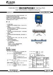
MEASURING PRINCIPLE<br />
Measuring<br />
chamber<br />
Sample gas<br />
Reference<br />
chamber<br />
This thermal conductivity gas analyzer measures gas concentration<br />
by utilizing the different thermal conductivities<br />
of 2 gas components. In the detector, there are reference<br />
and measuring chambers in each of which a thin platinum<br />
wire is stretched. The reference chamber is filled with reference<br />
gas and through the measuring chamber, sample<br />
gas is flowed. Each platinum wire composes a bridge circuit<br />
in combination with an external fixed resistor, and it is<br />
heated by flowing a constant current. When there is a change<br />
in the concentration of the component under measurement,<br />
the thermal conductivity of sample gas will change to affect<br />
the temperature of the platinum wire in the measuring<br />
chamber. The resulting thermal change is taken out as a<br />
change in electric resistance, according to which the concentration<br />
of measured gas is calculated.<br />
DC<br />
constant<br />
current<br />
Fixed resistor<br />
DC amplifier<br />
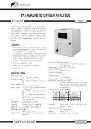
Thermal Conductivity Ratio of Gases<br />
Gases<br />
Sulfur dioxide gas<br />
Carbon dioxide gas<br />
Argon<br />
Carbon monoxide<br />
Steam (100°C)<br />
Air<br />
Nitrogen<br />
Oxygen<br />
Methane<br />
Hydrogen<br />
SO2<br />
CO2<br />
Ar<br />
CO<br />
H2O<br />
N2<br />
O2<br />
CH4<br />
H2<br />
Comparative thermal conductivity<br />
(0°C) when replacing thermal<br />
conductivity of air<br />
(2.41 x 10 -2 w/(m.k) with 1<br />
Table 1: Measurable Component and Measurable Range<br />
Measured gas<br />
H2<br />
He<br />
Ar<br />
CH4<br />
CO2<br />
Reference gas<br />
component (Note 1)<br />
N2, (CO2, Ar, He)<br />
N2, (CO2, Ar) O2,<br />
Air<br />
N2, O2, Air, (He)<br />
N2, (CO2, Ar, He)<br />
N2, O2, Air, (He)<br />
Measurable range<br />
0 to 3, 5, 10, 20, 50, 80, 100%<br />
100 to 90, 100 to 80%<br />
0 to 5, 10, 20, 30, 40, 50, 80, 100%<br />
100 to 90, 100 to 80%<br />
0 to 10, 20, 50, 80, 100%<br />
100 to 90, 100 to 80%<br />
0 to 20, 40, 50, 60, 80, 100%<br />
100 to 80%<br />
0 to 10, 20, 50, 100%<br />
100 to 90, 80%<br />
Range<br />
ratio(Note 2)<br />
1 : 10<br />
1 : 10<br />
(Note 1) Contact us for the components in the parentheses. H2 contained in O2 cannot be measured.<br />
(Note 2) Range ratio stands for maximum value.<br />
1 : 5<br />
1 : 5<br />
1 : 5<br />
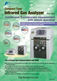
<strong>GAS</strong> SAMPLING SYSTEM DIAGRAM (EXAMPLE)<br />
Example of gas measurement in industrial furnace, sintering furnace, etc.<br />
Suction pump OFF signal in automatic calibration<br />
Sample<br />
gas<br />
(Note 1)<br />
Mist<br />
filter<br />
Gas<br />
aspirator<br />
(Note 2)<br />
Peltier gas<br />
cooler<br />
Flow<br />
checker<br />
Membrane<br />
filter<br />
0.4L/min (Note 3)<br />
or 1L/min<br />
1L/min<br />
Span calibration signal<br />
ZAF<br />
Exhaust<br />
Mist<br />
filter<br />
(Note 2)<br />
Drain pot<br />
Zero calibration signal<br />
Solenoid valve<br />
Purging<br />
air or<br />
nitrogen<br />
Pressure reducing valve<br />
Span<br />
gas<br />
Zero<br />
gas<br />
(Note 1) Dust must be purged adequately<br />
(for protection of the pump, flowmeter, etc.).<br />
(Note 2) Unnecessary if sample gas is dry.<br />
(Note 3) Select the one with no pulsating flow within the specified<br />
flow rate range.<br />
4