PARAMAGNETIC OXYGEN ANALYZER
PARAMAGNETIC OXYGEN ANALYZER - Fuji Electric
PARAMAGNETIC OXYGEN ANALYZER - Fuji Electric
- No tags were found...

Create successful ePaper yourself
Turn your PDF publications into a flip-book with our unique Google optimized e-Paper software.
<strong>PARAMAGNETIC</strong> <strong>OXYGEN</strong> <strong>ANALYZER</strong><br />
DATA SHEET<br />
ZKG<br />
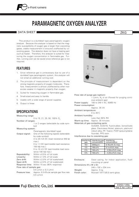
This product is a dumbbell type paramagnetic oxygen<br />
analyzer. Because this analyzer is based on that the magnetic<br />
susceptibility of oxygen gas is larger than coexisting<br />
gases, stable measurement is ensured unaffected by coexisting<br />
gases. The detector does not have a heating part<br />
such as heater. Therefore, this analyzer is suited for measuring<br />
the oxygen concentration in flammable gas. Further,<br />
running cost can be saved since reference gas is not<br />
required.<br />
FEATURES<br />
1. Since reference gas is unnecessary due to use of a<br />
dumbbell type paramagnetic system, this analyzer will<br />
not entail an additional running cost.<br />
2. The principle of measurement is dependent on the<br />
strong magnetic property of oxygen molecules. Therefore,<br />
measurement is almost unaffected by other molecules<br />
weaker in magnetic property than oxygen.<br />
3. Suited for measuring oxygen in flammable gas.<br />
4. Small-sized and easy to handle.<br />
5. Usable with a wide range of power supplies.<br />
6. Output is linear.<br />
SPECIFICATIONS<br />
Measuring range:<br />
0 to 10, 21, 25, 50, 100% O 2<br />
Number of ranges:<br />
1 or 2 ranges (selectable by code symbol)<br />
Measuring system:<br />
Paramagnetic (dumbbell type)<br />
Output signal: One of the following signals (selectable<br />
by code symbol)<br />
4 to 20 mA DC (load resistance 550 Ω<br />
max.)<br />
0 to 1 V DC (permissible load resistance<br />
100 kΩ max.)<br />
0 to 10 mV DC (permissible load resistance<br />
100 kΩ max.)<br />
Repeatability: Within ± 0.5% of full scale<br />
Linearity: Within ± 1.0% of full scale<br />
Zero drift: Within ± 2.0% of full scale/week<br />
Span drift: Within ± 2.0% of full scale/week<br />
Response time: Within 15 sec (90% response)<br />
Flow rate of sample gas:<br />
0.5 L/min ± 0.2 L/min<br />
Pressure loss: Approx. 0.3 kPa (at sample gas flow rate<br />
0.5 L/min)<br />
Flow rate of purge gas (option):<br />
1 L/min, N 2<br />
or air (flowed for purging corrosive<br />
ambient gas)<br />
Power supply: 100 to 240 V AC, 50/60 Hz<br />
Power consumption:<br />
Approx. 35 VA<br />
Ambient temperature:<br />
0 to 45˚C<br />
Ambient humidity:<br />
Less than 90% RH<br />
Warm-up time: Approx. 30 minutes<br />
Materials of gas-contacting parts:<br />
SUS304, SUS316, fluororubber, borosilicate<br />
glass, Electroless Nickel, platinum, platinum/<br />
iridium alloy, PP, Toaron, PVDF (polyvinylidene<br />
fluoride), PPS resin<br />
Interference due to coexisting gas:<br />
Interfering<br />
gas<br />
NO<br />
CO<br />
CO2<br />
CH4<br />
Interfering gas<br />
concentration<br />
2000ppm<br />
100vol%<br />
100vol%<br />
100vol%<br />
Interfering<br />
concentration<br />
0.15vol% O2 max.<br />
0.1vol%O2 max.<br />
– 0.35vol%O2 max.<br />
– 0.25vol%O2 max.<br />
Enclosure: Steel casing, for indoor application, flush<br />
mounting on panel<br />
Dimensions (H x W x D):<br />
240 x 192 x 234 mm<br />
Weight: Approx. 5 kg<br />
Finish color: Munsell 10Y7.5/0.5 semi-gloss<br />
EDS3-125b<br />
Date Apr. 1, 2011
ZKG<br />
Measuring gas conditions:<br />
Temperature: 0 to 50˚C<br />
Humidity: Dew point at least 10˚C lower<br />
than ambient temperature<br />
Dust: Max. 100 µg/Nm 3 in particles<br />
of max. 0.3 µm each<br />
Mist: Unallowable<br />
Pressure: 10 kPa or less<br />
Installation conditions:<br />
• The instrument must be protected from<br />
direct sunlight and heat radiation from objects<br />
at high temperature.<br />
• For installing the instrument outdoors, it<br />
must be protected from rain and wind with<br />
a suitable casing or cover.<br />
• The instrument must be installed in a clean<br />
atmosphere free from corrosive or flammable<br />
gas.<br />
• The instrument must be free from severe<br />
external vibrations.<br />
Mounting: Vertical mounting on panel<br />
Panel cutout dimensions (mm)<br />
CODE SYMBOLS<br />
1 2 3 4 5 6 7 8 9 10<br />
ZKG3Y<br />
2 -<br />
3<br />
1<br />
2<br />
3<br />
4<br />
5<br />
0<br />
1<br />
Y<br />
2<br />
3<br />
4<br />
5<br />
A<br />
B<br />
C<br />
Description<br />
Use (4th digit)<br />
With indication<br />
Measuring range (6th digit)<br />
0 to 10 vol%<br />
0 to 25 vol%<br />
0 to 50 vol%<br />
0 to 100 vol%<br />
0 to 21 vol%<br />
Purge inlet (7th digit)<br />
Without purge gas inlet<br />
With purge gas inlet<br />
2nd range (9th digit)<br />
Without<br />
0 to 25 vol%<br />
0 to 50 vol%<br />
0 to 100 vol%<br />
0 to 21 vol%<br />
Output signal (10th digit)<br />
DC 4 to 20mA<br />
DC 0 to 1V<br />
DC 0 to 10mV<br />
184<br />
+2<br />
0<br />
232 +2 0<br />
90˚<br />
PRINCIPLE OF MEASUREMENT<br />
Magnetic pole<br />
Double sphere<br />
(dumbbell)<br />
Magnetic pole<br />
Infrared ray source<br />
Hanging wire<br />
Reflecting mirror<br />
Light receiving element<br />
Feedback coil<br />
In the cell, two glass spheres filled with nitrogen<br />
gas are suspended with strong metal. At first,<br />
the spheres are kept in balance in an inhomogeneous<br />
magnetic field. When oxygen molecules<br />
having a large magnetic susceptibility flow there,<br />
the molecules are pulled toward the stronger magnetic<br />
field zone and the spheres are moved away<br />
from the zone. The resulting deviation of the<br />
spheres is detected with the light source, reflecting<br />
mirror and light receiving element, and a current<br />
is flowed through the feedback loop to control<br />
so that the spheres can return to the initial<br />
balanced state. The current flowing through the<br />
feedback loop is proportional to oxygen concentration.<br />
Thus, oxygen concentration is converted<br />
into an electric signal.<br />
2
CONFIGURATION<br />
Sampling System Diagram (example: Oxygen measurement in boiler exhaust gas)<br />
Gas extractor<br />
Gas inlet tube<br />
Drain<br />
separator<br />
Mist filter<br />
Aspirator<br />
Selector<br />
valve<br />
Flowmeter<br />
0.5L/min<br />
Membrane filter<br />
of 0.3 µm max.<br />
ZKG<br />
oxygen analyzer<br />
Exhaust release<br />
into atmosphere<br />
Electronic<br />
gas cooler<br />
Exhaust + drain<br />
Safety drain<br />
trap<br />
Regulation<br />
valve<br />
N2<br />
Zero gas<br />
Pressure regulator<br />
O2<br />
Span gas<br />
Standard gas for calibration<br />
Purge gas<br />
(when required)<br />
1L/min<br />
Air or N2<br />
SCOPE OF DELIVERY<br />
Analyzer main unit x 1<br />
Panel mounting bracket x 2<br />
Fuse 250 V AC/0.5 A delay type x 2 (1 accessory and 1 built in)<br />
Instruction manual x 1<br />
CAUTIONS<br />
(1) Use the analyzer within the specified flow rate. If it is<br />
used beyond the specified flow rate for enhancing response,<br />
the sensor section may be damaged to cause<br />
an instrument trouble.<br />
(2) Before the analyzer, be sure to connect a flowmeter<br />
and filter (0.3 µm or finer mesh).<br />
(3) Use a shielded wire for signal line connection.<br />
(4) Analyzer exhaust should be released into the atmospheric<br />
air.<br />
3
ZKG<br />
OUTLINE DIAGRAM (Unit : mm)<br />
Side View<br />
140<br />
t<br />
Panel<br />
1.6