Microjet Recorder Series
ECNO:1005l - Fuji Electric America
ECNO:1005l - Fuji Electric America

Create successful ePaper yourself
Turn your PDF publications into a flip-book with our unique Google optimized e-Paper software.
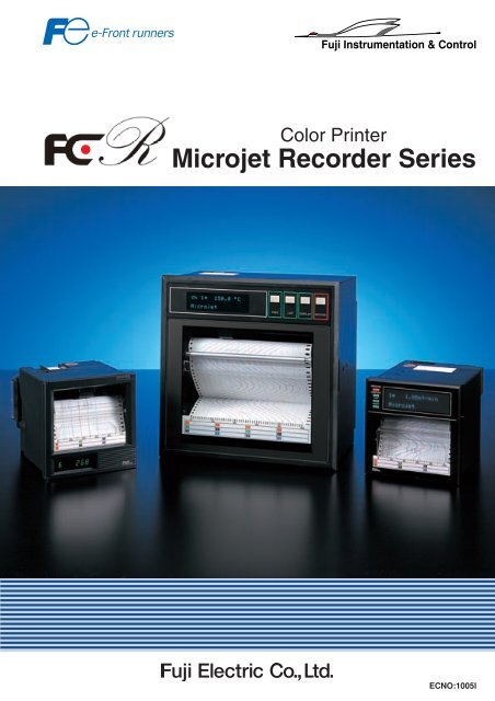
Fuji Instrumentation & Control<br />
Color Printer<br />
<strong>Microjet</strong> <strong>Recorder</strong> <strong>Series</strong><br />
ECNO:1005l
A Revolution in <strong>Recorder</strong> Technology<br />
Ink Jet Technology<br />
The ink jet head is formed on a<br />
stable quality silicon chip.<br />
The ink jet head printing mechanism<br />
does not touch the chart paper, allowing reliable<br />
recording.<br />
Piezo Element<br />
(Model :PHC)<br />
Nozzle<br />
The microjet recorder is a revolutionary recorder, its ink jet color<br />
printer technology is adopted in industrial type recorders for<br />
the first time in the world.<br />
Fuji established ink jet technology based on the unique silicon<br />
chip manufacturing process for FCX transmitters.<br />
The ink jet printing mechanism provides twelve continuous<br />
traces with a 180mm width recorder and six continuous trace<br />
with a 100mm width recorder without pen offset. The<br />
mechanism also provides six sharply defined colors.<br />
<strong>Microjet</strong> recorder was designed with a reduced number of<br />
complicated mechanical parts to make it as trouble-free as<br />
possible.<br />
The ink jet mechanism is formed on a thin silicon chip (17.6<br />
x 16mm) using silicon micro machining technology.<br />
It is provided with piezo elements.<br />
With voltage applied to the piezo elements, the shape of<br />
the elements changes as shown in the diagram, and ink<br />
particles are ejected from the tip of the nozzle.<br />
These particles are very small and fast, and draw a series of<br />
very small dots of about 0.3mm diameter on the chart paper.<br />
These small dots are combined together to form characters<br />
and trace lines for clear visible recording.<br />
1 2<br />
Ink
6 Color High Quality Trace<br />
Instantaneous value<br />
Chart speed<br />
Time<br />
Scale<br />
Time line<br />
Alarm ON<br />
<strong>Microjet</strong><br />
Alarm OFF<br />
Tag No./Tag name<br />
The ink jet printing mechanism allows<br />
continuous recording for a maximum<br />
of 12 channels (6 channels with 100mm<br />
width recorder) in 6 different colors.<br />
An A/D converter is used for each<br />
input signal for high speed data<br />
sampling to obtain a trace similar<br />
to that obtained by conventional pen<br />
mechanism recorders.<br />
Digital printing is also possible in<br />
the same color as the channel color,<br />
so clear and visible recording can<br />
be obtained. (for model PHA, PHC)<br />
3<br />
4
<strong>Microjet</strong> <strong>Recorder</strong><br />
PHC/PHA<br />
Report Generation<br />
(PHC)<br />
(PHA)<br />
Daily report/totalization<br />
On a daily report, measured values for every hour are printed<br />
along with maximum, minimum and average values.<br />
On a totalization, integrated values at intervals of 1 hour and<br />
the total value for one day are printed.<br />
Zoom, zone, auto-range trace<br />
Special traces that match the operating conditions of the plant<br />
are available.<br />
Logging print<br />
Printing of measured values at intervals of 10-60 minutes.<br />
Note: Analog trace is not available for logging printing.<br />
Parameter list, test pattern<br />
Configuration data can be checked with parameter list.<br />
A test pattern of all colors and all combinations of colors is<br />
available.<br />
Continuous recording<br />
6 colors<br />
180mm width, 12 channels<br />
100mm width, 6 channels<br />
Digital data printing in channel<br />
color<br />
Self-printing scale in channel<br />
color<br />
Tag No./Name printing in channel<br />
color, 8 digits (Max)<br />
Message printing in 6 color<br />
Long life recording<br />
6 months continuous operation with<br />
one cartridge.<br />
Color on each channel is<br />
selectable<br />
The following status printing is available<br />
for analyzing recording results.<br />
Alarm<br />
Red at alarm ON, black at alarm<br />
OFF, Channel No. and time are<br />
printed<br />
Burnout<br />
Ink shortage<br />
Recording start mark<br />
Chart speed change mark<br />
High reliability recording<br />
6 colors continuous trace<br />
Ink is not soluble in water, excellent<br />
water/sunlight resisting<br />
characteristics.<br />
Compact and light-weight design<br />
Mass (weight): 2.1kg/100mm width<br />
6.0kg/180mm width<br />
Depth: 199mm<br />
Simple choice<br />
The 100 and 180mm width recorders<br />
are configurable on each channel<br />
and accept most industrial inputs.<br />
The recorder operates on AC power<br />
100 to 240V.<br />
RS-485 Communications<br />
5
Simple Operation<br />
4-key operation (with door closed)<br />
German and French languages can be displayed.<br />
(PHC)<br />
A. Record start/stop key<br />
B. Display select key<br />
C. Measured value print key<br />
D. Chart feed key<br />
(PHA)<br />
4-key configuration (with door open)<br />
Configuration can be done according to operation guide<br />
(PHC)<br />
E. Select key<br />
F. Up key<br />
G.Down key<br />
H. Data entry key<br />
(PHA)<br />
Simple Design<br />
Simple Design<br />
The ink jet mechanism is simple<br />
in design.<br />
Electronic parts are increasingly<br />
used in the recorder.<br />
Mechanical parts have been<br />
reduced to about 1/3 that of<br />
conventional recorders and it<br />
comprises about 2/3 of the total<br />
number of parts.<br />
The small size (199mm deep)<br />
contributes to panel cost saving.<br />
Fully Configurable input<br />
This recorder accepts multiple<br />
inputs.<br />
With a process input, it can record<br />
and print the results of filter,<br />
square-root extraction, subtraction<br />
calculation and scaling for each<br />
channel.<br />
Reduced Maintenance<br />
Complicated servo mechanism is<br />
not used.<br />
Each input has its own input<br />
circuit.<br />
Unlike conventional recorders,<br />
input scanning relays are not<br />
used and hence trouble-free<br />
operation is ensured.<br />
6
Specification Summary<br />
Model PHC PHA<br />
Chart width/length 100mm/15m 180mm/20m<br />
No. of input channel 3/6 6/12<br />
Input Signal type<br />
TC (J, K, E, R, B, S, T, L, U, W, PN, N), RTD, DC V (50mV, 500mV, 5V, 50V DC), DC mA<br />
Measuring cycle 160/320ms. 320ms.<br />
Accuracy<br />
Display<br />
Display Accuracy<br />
Analog Trace<br />
Accuracy<br />
0.15% of measuring range, 1 digit without cold junction compensation error<br />
Display accuracy 0.25% of measuring range<br />
Fluorescent (20 characters x 2 lines)<br />
Chart speed<br />
Recording cycle<br />
5-400mm/h continuous trace<br />
401-1500mm/h<br />
intermittent trace<br />
Recording<br />
400<br />
=<br />
cycle (sec.) Chart speed (mm/h)<br />
Recording cycle is more than 2 seconds.<br />
5-300mm/h continuous trace<br />
301-1500mm/h<br />
intermittent trace<br />
Recording<br />
450<br />
=<br />
cycle (sec.) Chart speed (mm/h)<br />
Recording cycle is more than 3 seconds.<br />
Calculation *<br />
Report Generation<br />
Alarm<br />
Square root extraction, Subtraction, Scaling, Input filter, Logarithm<br />
Daily report, Totalize list, Parameter list, Test pattern, Measured value list, Logging print, Message print<br />
H, L, RH, RL for each input, Burnout, Ink-out, Chart end, Battery alarm<br />
Alarm output 6 Relay output 6/12 Relay output<br />
Option<br />
Remote control<br />
Record start/stop, Chart speed change, Measured value print, Message print<br />
Communication RS-485 RS485, T-Link<br />
Chart Illumination<br />
Cold cathode fluorescent<br />
Power supply<br />
100-120V AC or 200-240V AC<br />
(Usable Range 85-150VAC or 150-300VAC)<br />
100-240V AC<br />
(Usable Range 85-300VAC)<br />
Environmental<br />
Temperature: 0 to 50°C IEC IP50<br />
Humidity: 20 to 80%RH<br />
(Temp. (°C) x Humi. (%RH) < 3200)<br />
Mass {weight} Approx. 2.1kg (without options) 6kg (without options)<br />
* Consult Fuji Electric Instruments for additional features not listed such as flow<br />
integration record and calculation of input signal, etc.<br />
7
Code Symbols<br />
<br />
<br />
<br />
<br />
<br />
<br />
Description<br />
<br />
<br />
<br />
<br />
<br />
Description<br />
3 3<br />
6 6<br />
7 6<br />
A<br />
E<br />
A<br />
B<br />
0<br />
1<br />
2<br />
Y<br />
R<br />
Recording points<br />
3 continuous recording<br />
6 continuous recording<br />
6 intermittent recording<br />
Power Supply<br />
100 to 120V AC 50/60Hz<br />
200 to 240V AC 50/60Hz<br />
Chart paper illumination<br />
Without<br />
With<br />
Alarm output/external control<br />
Without<br />
6-point alarm output (N.O.)/<br />
3-point external control<br />
6-point alarm output (N.C.)/<br />
3-point external control<br />
Transmission function<br />
Without<br />
With RS-485<br />
6 6<br />
7 6<br />
8 8<br />
9 8<br />
A<br />
B<br />
0<br />
1<br />
2<br />
Y<br />
R<br />
T<br />
Recording points<br />
6 continuous recording<br />
6 intermittent recording<br />
12 intermittent recording<br />
12 continuous recording<br />
Chart paper illumination<br />
Without<br />
With<br />
Alarm output/external control<br />
Without<br />
6-point alarm output/3-point<br />
external control<br />
12-point alarm output/3-point<br />
external control<br />
Transmission function<br />
Without<br />
With RS-485<br />
With T-Link<br />
Note) 1. Input signal<br />
Setting prior to delivery is as follows;<br />
• Thermocouple K: 0 to 1200˚C<br />
2. Shunt resistor (10 0.1%) should be ordered separately for current input.<br />
Shunt resistor : Ordering code PHZT8101 for PHA, PHZT1101 for PHC<br />
3. T-Link transmission function is Fuji's original PLC Link transmission function<br />
Dimension of PHC (100mm width)<br />
Dimension of PHA (180mm width)<br />
<br />
<br />
<br />
<br />
<br />
<br />
<br />
<br />
<br />
<br />
8
<strong>Microjet</strong> <strong>Recorder</strong>-E<br />
PHE<br />
Specification Summary<br />
Inkjet technology, previously available only on<br />
expensive printers, is now available on a strip chart<br />
recorder at an affordable price, a price that falls<br />
below the cost of some dot matrix type printers.<br />
If you note the comparison between the dot matrix<br />
and inkjet typeface, there simply is no reason to use<br />
a dot matrix type recorder anymore.<br />
This recorder has basically 2 models, user programmable<br />
model and factory configuration model.<br />
Factory can pre-configure recorder parameters with<br />
customer supplied information prior to shipment, reducing<br />
the users' total installation cost and time.<br />
In case of 1 or 2 continuous recording, 2-color type Ink<br />
cartridge (PHZH2002) is also available.<br />
Since its life-span became longer than before, you can cut<br />
the running-cost in 1/4-1/2.<br />
Real time clock (calendar) function is available with<br />
standard specification.<br />
Model PHE1 PHE2 PHE7, 8, 9<br />
Chart width/length<br />
100mm/15m<br />
No. of input channel 1 2 6<br />
Signal type<br />
Input/Recording range<br />
TC (J, K, E, R, B, S, T, L, U, W, PN, N), RTD, DC V (50mV, 500mV, 5V, 50V DC), DC mA<br />
User programmable or factory configuration<br />
Measuring cycle<br />
200ms/point<br />
30s/all point with input<br />
scanning relay<br />
Accuracy<br />
Display<br />
Display<br />
Accuracy<br />
Analog trace<br />
Accuracy<br />
<br />
Display accuracy 0.2% of measuring range<br />
LED (7 segments x 6 digits)<br />
Chart speed<br />
Recording cycle<br />
10/20/24/30/50/120/200/300/400 mm/h<br />
Recording<br />
400<br />
=<br />
cycle (sec.) Chart speed (mm/h)<br />
Recording cycle is more than 2 seconds.<br />
10/20/24/30/50/120/200/300/<br />
400/1000/1200/1500 mm/h<br />
30s/all point<br />
Printing<br />
function<br />
Alarm<br />
During analog<br />
recording<br />
Independent<br />
of analog<br />
recording<br />
Other<br />
Channel No., Periodic data, Scale, Alarm, Burnout, Date and Time<br />
Instantaneous value list, Parameter list, Scale list, Test Pattern<br />
Recording start mark, Chart speed change mark<br />
L/LL, H/L, H/HH<br />
Option<br />
Power supply<br />
Alarm output 2 relay output 4 relay output 6 relay output<br />
Remote control<br />
Chart speed change<br />
100-120V AC or 200-240V AC<br />
Environmental<br />
Temperature: 0 to 50°C IEC IP50<br />
Humidity: 20 to 80%RH<br />
(Temp. (°C) x Humi. (%RH) < 3200)<br />
Mass {weight} Approx. 1.2kg (without option) 1.2kg (without option) 1.5kg (without option)<br />
9
Code Symbols<br />
User programmable model<br />
<br />
<br />
<br />
1<br />
2<br />
9<br />
1<br />
2<br />
3<br />
4<br />
0<br />
1<br />
2<br />
3<br />
A<br />
B<br />
C<br />
<br />
Description<br />
Recording points<br />
1 continuous recording<br />
2 continuous recording<br />
6 intermittent recording<br />
Power SupplyTemperature Unit<br />
100 to 120V AC 50/60Hz ˚C<br />
200 to 240V AC 50/60Hz ˚C<br />
100 to 120V AC 50/60Hz ˚F<br />
200 to 240V AC 50/60Hz ˚F<br />
Alarm output/external control input<br />
(1 point)<br />
Without<br />
2 points alarm output<br />
(1 continuous only)<br />
4 points alarm output<br />
(2 continuous only)<br />
6 points alarm output<br />
(6 intermittent only)<br />
2 points alarm output/External control<br />
(1 continuous only)<br />
4 points alarm output/External control<br />
(2 continuous only)<br />
6 points alarm output/External control<br />
(6 intermittent only)<br />
Input : Universal (Programmable)<br />
Range : Field settable (Programmable)<br />
Note) 1. Input signal<br />
Setting prior to delivery is as follows;<br />
• Thermocouple K: 0 to 1200˚C<br />
2. Shunt resistor (10 0.1%) should be<br />
ordered separately for current input.<br />
Shunt resistor : Ordering code PHZT 1101<br />
Factory configuration model<br />
<br />
<br />
<br />
<br />
1<br />
2<br />
7<br />
8<br />
<br />
1<br />
2<br />
3<br />
4<br />
<br />
<br />
Description<br />
Recording points<br />
1 continuous recording<br />
2 continuous recording<br />
6 intermittent recording (single scale)<br />
6 intermittent recording (double scale)<br />
Input signal<br />
1 continuous Y<br />
2 continuous <br />
6 intermittent (single range) Y<br />
6 intermittent (double range) <br />
Symbols of input signals<br />
X...... B thermocouple R...... R thermocouple<br />
S...... S thermocouple K...... K thermocouple<br />
E...... E thermocouple J...... J thermocouple<br />
T...... T thermocouple N...... N thermocouple<br />
W...... W thermocouple L...... L thermocouple<br />
U...... U thermocouple P...... PN thermocouple<br />
H...... Pt100<br />
A...... 1 to 5V DC B...... 4 to 20mA DC *1<br />
C...... 10 to 50mA DC *1 M...... 50mV DC<br />
O...... 500mV DC V...... 5V DC<br />
F...... 50V DC<br />
Power supply Temperature Unit<br />
100 to 120VAC 50/60Hz <br />
200 to 240VAC 50/60Hz <br />
100 to 120VAC 50/60Hz <br />
200 to 240VAC 50/60Hz <br />
measuring range<br />
1 continuous Y<br />
2 continuous <br />
6 intermittent (single scale) Y<br />
6 intermittent (double scale) <br />
measuring range code are specified for<br />
each input signal.<br />
0<br />
1<br />
2<br />
3<br />
A<br />
B<br />
C<br />
Alarm output/external control input (1 point)<br />
Without<br />
2 points alarm output (1 continuous only)<br />
4 points alarm output (2 continuous only)<br />
6 points alarm output (6-intermittent only)<br />
2 points alarm output/External control<br />
(1 continuous only)<br />
4 points alarm output/External control<br />
(2 continuous only)<br />
6 points alarm output/External control<br />
(6 intermittent only)<br />
Y Y<br />
E Y<br />
Instruction manual<br />
Not attached<br />
English<br />
Note) <strong>Recorder</strong> will be shipped with 10shunt<br />
resistor attached to terminal for current input.<br />
For intermittent double scale type, 2 kind of<br />
recording range and unit should be specified.<br />
One is for channel 1 to channel 3, the other is<br />
for channel 4 to channel 6.<br />
Outline diagrams<br />
Continuous type<br />
Intermittent type<br />
<br />
<br />
<br />
<br />
10
International Sales Div.<br />
Sales Group<br />
Gate City Ohsaki, East Tower, 11-2, Osaki 1-chome,<br />
Shinagawa-ku, Tokyo 141-0032, Japan<br />
http://www.fujielectric.com<br />
Phone: 81-3-5435-7280, 7281 Fax: 81-3-5435-7425<br />
http://www.fujielectric.com/products/instruments/<br />
Information in this catalog is subject to change without notice.<br />
Printed in Japan 2011-4/20FOLS