MICROJET RECORDER-E
FCR Microjet Recorder-E (100mm) - Fuji Electric
FCR Microjet Recorder-E (100mm) - Fuji Electric

Create successful ePaper yourself
Turn your PDF publications into a flip-book with our unique Google optimized e-Paper software.
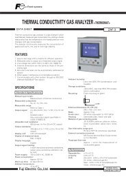
<strong>MICROJET</strong> <strong>RECORDER</strong>-E<br />
DATA SHEET<br />
PHE<br />
This recorder can record up to 6 channels of thermocouples,<br />
resistance bulbs and DC voltage/current signals.<br />
The adoption of ink jet system makes it possible to record<br />
measured data in analog trace and digital color printing (6<br />
colors, max) on a 100mm wide chart paper.<br />
FEATURES<br />
1. Compact size<br />
Depth: 175mm, mass; about 1.2kg (continuous type)<br />
Depth: 197mm, mass; about 1.5kg (6-intermittent type)<br />
Ideally suited for use with machines and equipments.<br />
2. High-quality recording<br />
• Continuous traces without pen offset are possible by<br />
our unique ink jet system.<br />
• Scales are printed on a chart paper for each channel,<br />
eliminating the need for scale plate.<br />
• 6 different scale on 6 intermittent recording universal<br />
input type is available.<br />
3. Easy setting of input signals<br />
DC voltage input (5mV span, 50V max.), DC current<br />
(4-20mA, 10-50mA), 12 kinds of thermocouples and resistance<br />
bulbs (Pt100) are field-settable for each channel.<br />
4. Digital printing<br />
In addition to analog recording of measured data, periodic<br />
data printing, measured value list, scale printing,<br />
alarm printing, burnout printing, and parameter list are<br />
also available.<br />
5. Easy Operation<br />
• A cartridge type recording device is used for easy<br />
replacement.<br />
• Allow to draw out the chart paper while recording.<br />
SPECIFICATIONS<br />
Input system<br />
Input points: 1, 2-continuous recording, 6-intermittent<br />
recording<br />
Input signal: Thermocouple: B, R, S, K, E, J, T, N, W, L,<br />
U, PN<br />
Resistance bulb: Pt100<br />
DC voltage: 5 0 m V, 5 0 0 m V, 5 V, 5 0 V<br />
range<br />
DC current: 4 to 20mA DC, 10 to 50mA<br />
DC (Shunt resistor (option)<br />
need to be connected to<br />
the terminal.)<br />
Input signal setting and change:<br />
Setting and change of input signal between<br />
thermocouple, resistance bulb<br />
and DC voltage (50mV, 500mV, 5V, 50V<br />
range) is possible for each channel by<br />
the setting pin in the instrument and<br />
keyboard operation.<br />
Measuring range (Recording range):<br />
Recording range on each channel is settable<br />
within the raference range with<br />
keyboard operation.<br />
Measurement cycle:<br />
1, 2-continuous: 0.2s/point<br />
6-intermittent: 30s/all points<br />
Burnout: When thermocouple or resistance bulb<br />
input is disconnected, the recording is<br />
deflected to 100%.<br />
Input filter: Settable within the range of 0-255s by<br />
1s. steps.<br />
Initial set before delivery is 3 s.<br />
Reference range<br />
Input signal<br />
Thermocouple B<br />
R<br />
S<br />
K<br />
E<br />
J<br />
T<br />
N<br />
W<br />
L<br />
U<br />
PN<br />
Resistance bulb Pt 100<br />
DC voltage ±50mV<br />
±500mV<br />
±5V<br />
±50V<br />
Scaling<br />
Recording system<br />
°C<br />
400 to 1760<br />
0 to 1760<br />
0 to 1760<br />
-200 to 1370<br />
-200 to 800<br />
-200 to 1100<br />
-200 to 400<br />
0 to 1300<br />
0 to 1760<br />
-200 to 900<br />
-200 to 400<br />
0 to 1300<br />
°F<br />
752 to 3200<br />
32 to 3200<br />
32 to 3200<br />
-328 to 2498<br />
-328 to 1472<br />
-328 to 2012<br />
-328 to 752<br />
32 to 2372<br />
32 to 3200<br />
-328 to 1652<br />
-328 to 752<br />
32 to 2372<br />
-200 to 600<br />
-328 to 1112<br />
-50.00 to 50.00mV<br />
-500.0 to 500.0mV<br />
-5.000 to 5.000V<br />
-50.00 to 50.00V<br />
Scaling is possible within the range of<br />
-32767 to +32767 (decimal point may<br />
be put as necessary)<br />
Writing system: Ink jet system, in 6 colors as max.<br />
Chart width: 100mm<br />
Chart length: Z fold 15.08m<br />
Service life of ink (depends on operating conditions):<br />
About 12 months for 1 continuous line<br />
recording at 20mm/h of chart speed.<br />
EDSX10-70c<br />
Date Apr. 1, 2011
PHE<br />
Recording color: 1-continuous: Recording: purple<br />
Printing: purple<br />
2-continuous: Recording:<br />
No. 1 channel, red<br />
No. 2 channel, blue<br />
Printing: purple<br />
6-intermittent recording:<br />
No. 1 channel, orange<br />
No. 2 channel, green<br />
No. 3 channel, purple<br />
No. 4 channel, red<br />
No. 5 channel, black<br />
No. 6 channel, blue<br />
Printing: black<br />
Chart speed: 10, 20, 24, 30, 50, 120, 200, 300, 400,<br />
1000, 1200, 1500 mm/h<br />
Can be changed by key operation.<br />
Initial set before delivery is 20mm/h<br />
(Note) In continuous type, it records<br />
data intermittently when the speed exceeds<br />
400mm/h.<br />
Recording cycle: Continuous recording:<br />
Depend on chart speed<br />
[Calculation formula]<br />
400<br />
Recording cycle (sec) =<br />
chart speed (mm/h)<br />
(not faster than 2 seconds.)<br />
Intermittent recording:<br />
30 s/all points.<br />
Industrial unit: Selectable on each channel in max. 7<br />
characters by ASCII code.<br />
Printing function:[Printing during analog recording]<br />
[Note] Chart speed of continuous type<br />
should be slower than 400mm/<br />
h and that of intermittent type<br />
should be slower than 50mm/h.<br />
Channel No. printing: Beside of recording<br />
line<br />
Periodic printing: Channel number, measurement<br />
value, unit,<br />
chart speed and year,<br />
month, day, hour, minute.<br />
[Note] Print period is automatically fixed<br />
on chart speed.<br />
Scale printing: This print out is effected<br />
alternately with periodic<br />
printing.<br />
[Note] Print interval is automatically<br />
fixed on chart speed.<br />
Alarm printing: Channel number, kind of<br />
alarm and hour, minute.<br />
Burnout printing: Channel number and<br />
hour, minute.<br />
[Printing independent of analog recording]<br />
[Note] Printing is performed by key operation,<br />
while analog recording<br />
is interrupted. After completion<br />
of the printing, analog recording<br />
starts again.<br />
Instantaneous value list:Channel number,<br />
measured value,<br />
industrial unit, year,<br />
month, day, hour,<br />
minute.<br />
Parameter list (set value list):<br />
Input signal, recording<br />
range, measuring range,<br />
s c a l i n g r a n g e , u n i t ,<br />
alarm, input filter, chart<br />
speed, year, month, day,<br />
hour, minute, etc.<br />
Scale line printing: Optional scale line<br />
by user.<br />
Test pattern: All characters and color<br />
patterns can be printed.<br />
[Other printing]<br />
Recording start mark<br />
Chart speed change mark<br />
Indicating, key operation system<br />
Indication: LED (7 segments), 6 digits, green<br />
Indication character:<br />
7 segments, alphanumeral<br />
Character height 10mm, width 5mm<br />
Contents of indication:<br />
Channel No.: 1 digit (1 to 6)<br />
Measured value:<br />
5 digits (including sign for<br />
value below 0)<br />
Temperature: 1 d i g i t b e l ow d e c i m a l<br />
point<br />
Voltage/current:<br />
Scaling, -9999 is displayed<br />
for -10000 and under.<br />
Time: Hour, Minute<br />
Status indication:<br />
Symbolic code as alarm,<br />
burnout or carriage failure.<br />
Measurement display cycle:<br />
3s for channel selection,<br />
1s for data update in the<br />
same channel<br />
Operation key: 3 keys and 1 reset key<br />
Key lock: soft key lock is available by<br />
key operation.<br />
Power requirement<br />
Line supply: Specify when ordering<br />
Rated voltage<br />
100 to 120VAC or 200 to 240VAC<br />
Usable voltage<br />
85 to 132VAC or 180 to 264VAC<br />
Frequency: 50/60Hz<br />
Power consumption:<br />
100 to 120VAC or 200 to 240VAC, without<br />
option, 13VA or less<br />
100 to 120VAC or 200 to 240VAC, with<br />
alarm, 15VA or less<br />
2
Alarm<br />
Type:<br />
Setting:<br />
Indication:<br />
Printing:<br />
Hysteresis:<br />
Alarm output:<br />
Physical data<br />
Mounting:<br />
Absolute value alarm, high and low<br />
Two levels for each channel (high: 2 levels,<br />
low: 2 levels, or each level at high/<br />
low)<br />
Alarm level is indicated for each channel<br />
at occurrence of alarm.<br />
Channel No. alarm level and hour, minute.<br />
Approx. 0.2% of measuring (recording)<br />
range<br />
See “Optional specifications”.<br />
Panel (may be inclined up to 30° backwards<br />
from the vertical)<br />
Two or more recorders can be mounted<br />
side by side.<br />
Panel thickness: 2 to 30mm<br />
Material: Case: mold Front door frame: mold<br />
Finish color: Case: black Front door frame: black<br />
Protective structure:<br />
Front door: IEC IP50<br />
Case size: Bezel 144 x 144mm<br />
Depth 175mm (Continuous type)<br />
195mm Intermittent type)<br />
Cutout 137 x 137mm<br />
External terminals:<br />
Screw terminals (M4 screw)<br />
Mass:<br />
Approx. 1.2kg (continuous type)<br />
Approx. 1.5kg (intermittent type)<br />
External terminals: M4 screw<br />
Performance and characteristics<br />
Indication accuracy*1:<br />
DC voltage, DC current :<br />
±(0.3% of measuring range +1 digit)<br />
Thermocouple, Resistance bulb:<br />
Depend on the measuring range for<br />
each input signal.<br />
Refer to the table below.<br />
input<br />
signal<br />
B<br />
(0.3% of measuring range+1 digit)<br />
measuring range<br />
1000°C or more 1832°F or more<br />
= 90 to 60°<br />
(1% of measuring range+1 digit)<br />
measuring range<br />
600°C or more 1112°F or more<br />
R 1000°C or more 1832°F or more 600°C or more 1112°F or more<br />
S 1000°C or more 1832°F or more 600°C or more 1112°F or more<br />
K 300°C or more 572°F or more 200°C or more 392°F or more<br />
E 300°C or more 572°F or more 200°C or more 392°F or more<br />
J 300°C or more 572°F or more 200°C or more 392°F or more<br />
T 300°C or more 572°F or more 200°C or more 392°F or more<br />
N 300°C or more 572°F or more 200°C or more 392°F or more<br />
W 500°C or more 932°F or more 400°C or more 752°F or more<br />
L 300°C or more 572°F or more 200°C or more 392°F or more<br />
U 300°C or more 572°F or more 200°C or more 392°F or more<br />
PN 300°C or more 572°F or more 200°C or more 392°F or more<br />
Pt100 150°C or more 302°F or more 50°C or more 122°F or more<br />
Resolution*1: Thermocouple input : 0.1°C 0.1°F<br />
Resistance bulb : 0.1°C 0.1°F<br />
DC voltage : ±50mV : 10µV<br />
: ±500mV : 100µV<br />
: ±5V : 1mV<br />
: ±50V : 10mV<br />
DC current : converted value to<br />
DC voltage is guaranteed<br />
Recording accuracy *1:<br />
Indication accuracy ±(0.2% of measuring<br />
range)<br />
Recording resolution:<br />
0.1mm<br />
Chart speed accuracy:<br />
±0.1% (in case continuous feed of<br />
more than 1m. Expansion and contraction<br />
of paper is not included)<br />
Reference junction compensation accuracy:<br />
K, E, J, T, N, L, U, PN : ±0.5°C<br />
B, R, S, W : ±1°C<br />
90% response time:<br />
Less than 2s (continuous type only)<br />
Maximum input voltage:<br />
Thermocouple, resistance bulb and DC<br />
voltage (50mV, 500mV range):<br />
±10V DC or less<br />
DC 5V/50V range: ±100V DC or less<br />
Input resistance: Thermocouple, 50mV voltage range<br />
> 10MΩ<br />
5V/50V range: > 1MΩ<br />
500mV range: > 100kΩ<br />
Isolation: 100MΩ (between each terminal and<br />
earth at 500V DC)<br />
Channel to channel:<br />
500V AC, 1min<br />
Power terminal to ground: 2000V AC,<br />
1min<br />
Input terminal to ground: 500V AC,<br />
1min<br />
Power terminal to input terminal: 1000V<br />
AC, 1min<br />
Alarm to alarm: 750V AC, 1min<br />
(leak current: 5mA or less)<br />
Common mode noise rejection:<br />
120dB (50/60Hz)<br />
Series mode noise rejection:<br />
30dB (50/60Hz)<br />
Clock accuracy: ±50ppm (2 minutes per month)<br />
Memory protection: Non-volatile memory for parameters.<br />
Lithium battery for clock.<br />
[Note] *1 Measurement condition:<br />
23±2°C, 65±10%RH, power voltage<br />
100 to 120V, 200 to 240V, frequency<br />
50/60Hz within 1%, warm-up time<br />
30min or more, vertical mounting, and<br />
free from the effects of vibration, noise,<br />
etc.<br />
[Note] 1. For thermocouple input, in case of measuring<br />
range includes -200°C to -100°C (-328°F to -148°F),<br />
indication accuracy should be added +0.5%.<br />
2. The indication accuracy of thermocouple does not<br />
include reference junction compensation error.<br />
3
PHE<br />
Operating environment<br />
Temperature limits: 0 to 50°C<br />
Humidity limits: 20 to 80%RH<br />
(temperature × humidity < 3200)<br />
Mounting position:<br />
Front inclination 0°, rear inclination 30°,<br />
left/right inclination 0°<br />
Signal source resistance:<br />
Thermocouple input: 1kΩ or less<br />
Resistance bulb input: Less than 10Ω<br />
(line resistance of each wire of 3-wires<br />
system should be balanced)<br />
Voltage input: Less than 0.1% of input<br />
resistance<br />
Vibration: 10 to 60Hz, 0.2m/s 2 or less<br />
Shock:<br />
None<br />
Optional specifications<br />
Alarm output (DO):<br />
2, 4 or 6 points N.O contact relay (refer<br />
to code symbols)<br />
Contact capacity 250V AC/3A.<br />
30V DC/3A (resistance load)<br />
Alarm output unit is required.<br />
External control input (DI):<br />
1 point, no-voltage contact input is<br />
used for selection of chart speed in 2<br />
steps.<br />
Normally, operation is effected at main<br />
chart speed.<br />
Sub-speed is selected with contact<br />
ON, and main speed with contact OFF.<br />
Main/sub speed is set by key operation.<br />
When sub-speed is set to 0mm/h, recording<br />
start/stop can be selected.<br />
Alarm output /external control input unit<br />
is required.<br />
Other functions<br />
Printing/recording adjustment:<br />
Make adjustment when characters<br />
bend and/or disturbance of record (round<br />
trip difference) occur.<br />
Adjustment of zero/span of analog trend record position:<br />
The position of ink cartridge is adjusted<br />
for correct recording on 0% point and<br />
100% point on chart paper.<br />
This adjustment should be made after<br />
replacement of ink cartridge or chart<br />
paper.<br />
Measured value shift:<br />
Indication or recording value is shifted<br />
by adding or subtracting calculation of<br />
measured value.<br />
Sub chart speed: This is for selecting chart speed with<br />
external control input. It is selected<br />
from the following.<br />
0, 10, 20, 30, 50, 120, 200, 300, 400,<br />
1000, 1200, 1500mm/h<br />
Initial set before delivery: 20mm/h<br />
0mm/h means stop recording.<br />
Channel skip: This is used to stop the operation of<br />
unused channel. Skipped channel stops<br />
all operations including display and<br />
alarm.<br />
Setting recording status at power ON:<br />
Recording can be started again or<br />
disabled when power is ON or when<br />
power is recovered from failure.<br />
Real time clock: Setting year, month, day, hour, minute<br />
4
CODE SYMBOLS<br />
1 2 3 4 5 6 7 8 9 10 11 12 13<br />
P H E 0 0 2 V V E V<br />
1<br />
2<br />
9<br />
1<br />
2<br />
3<br />
4<br />
0<br />
1<br />
2<br />
3<br />
A<br />
B<br />
C<br />
Description<br />
Recording points <br />
1 continuous recording<br />
2 continuous recording<br />
6 intermittent recording<br />
Power supply • Temperature Unit <br />
100 to 120VAC 50/60Hz °C<br />
200 to 240VAC 50/60Hz °C<br />
100 to 120VAC 50/60Hz °F<br />
200 to 240VAC 50/60Hz °F<br />
Alarm output/external control input (1 point) <br />
Without<br />
2 points alarm output (1 continuous only)<br />
4 points alarm output (2 continuous only)<br />
6 points alarm output (6-intermittent only)<br />
2 points alarm output/External control (1 continuous only)<br />
4 points alarm output/External control (2 continuous only)<br />
6 points alarm output/External control (6 intermittent only)<br />
Input : Universal (Programmable)<br />
Range: Field settable (Programmable)<br />
Note) 1. Initial set before delivery is ;<br />
• Thermocouple K type 0 to 1200°C<br />
2. Shunt resistor (10Ω ±0.1%) should be ordered separately for<br />
current input.<br />
Shunt Resister : Ordering code PHZT1101<br />
3. When changing the kinds of input signal, some adjustments<br />
may become necessary.<br />
SCOPE OF DELIVERY<br />
Recorder, panel mounting bracket, accessories<br />
(ink cartridge 1 pc, chart paper 1 roll, input signal setting pin<br />
for replacement 1pc, ink absorption cloth 1 sheet). instruction<br />
manual (1 copy)<br />
Note: Ink cartridge is not mounted on the recorder at the<br />
time of delivery.<br />
Spare parts<br />
Item<br />
Ink cartridge<br />
Chart paper<br />
(0 to 50, 50 uniform<br />
division)<br />
Part No.<br />
PHZH2002<br />
(1, 2-continuous)<br />
PHZH1002<br />
(6-intermittent)<br />
PEX00DL1 - 5000B<br />
Unit of quantity for sale<br />
1 pc<br />
1 pc<br />
1 box (6 charts)<br />
Other (optional items)<br />
Item<br />
Shunt resistor<br />
Type<br />
PHZT1101<br />
Specification<br />
For 10Ω±0.1%<br />
5
PHE<br />
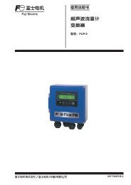
OUTLINE DIAGRAM (Unit:mm)<br />
1-continuous type<br />
Mounting bracket<br />
Alarm output /external control input unit(option)<br />
2 <<br />
=<br />
T <<br />
=<br />
30<br />
t<br />
Panel<br />
161<br />
136.5<br />
144<br />
Power terminal<br />
136.4 175<br />
19 144<br />
197<br />
Input terminal<br />
Panel cutout<br />
When mounting one unit<br />
When mounting multiple n unit<br />
137 +1.5 0<br />
L +1.5 0<br />
137 +1.5 0<br />
137 +1.5 0<br />
175MIN<br />
No. of units +1.5<br />
L 0 (mm)<br />
2 282<br />
3 426<br />
4 570<br />
5 714<br />
6 858<br />
7 1002<br />
8 1146<br />
9 1290<br />
10 1434<br />
n (144 x n) – 6<br />
Connection diagram<br />
Alarm output / external control input unit<br />
11<br />
21<br />
12 22<br />
13 23<br />
14 24<br />
15 25<br />
16 26<br />
17 27<br />
18 28<br />
19 29<br />
Alarm output 1<br />
Alarm output 2<br />
Not used<br />
Not used<br />
Not used<br />
Not used<br />
External control input<br />
Not used<br />
Not used<br />
Power terminal Input terminal<br />
100 to 120VAC or<br />
200 to 240VAC<br />
RTD<br />
50/60HZ<br />
~<br />
+ – TC<br />
V<br />
L N PE 11 12 13<br />
6
OUTLINE DIAGRAM (Unit:mm)<br />
2-continuous type<br />
Alarm output /external control input unit(option)<br />
Mounting bracket<br />
2<br />
=<br />
< T <<br />
=<br />
30<br />
t<br />
Panel<br />
161<br />
136.5<br />
144<br />
Power terminal<br />
136.4 175<br />
19 144<br />
197<br />
Input terminal<br />
Panel cutout<br />
When mounting one unit<br />
When mounting multiple n unit<br />
137 +1.5 0<br />
137 +1.5 0<br />
137 +1.5 0<br />
L +1.5 0<br />
175MIN<br />
No. of units<br />
+1.5<br />
L 0 (mm)<br />
2 282<br />
3 426<br />
4 570<br />
5 714<br />
6 858<br />
7 1002<br />
8 1146<br />
9 1290<br />
10 1434<br />
n (144 x n) – 6<br />
Connection diagram<br />
Alarm output /external control input unit<br />
11<br />
21<br />
12 22<br />
13 23<br />
14 24<br />
15 25<br />
16 26<br />
17 27<br />
18 28<br />
19 29<br />
Alarm 1<br />
Alarm 2<br />
Alarm 3<br />
Alarm 4<br />
Not used<br />
Not used<br />
External control input<br />
Not used<br />
Not used<br />
Power terminal Input terminal<br />
100 to 120VAC or<br />
200 to 240VAC<br />
RTD<br />
50/60HZ<br />
+ – + – TC<br />
~<br />
V<br />
L N PE 21 22 23 11 12 13<br />
Input 2 Input 1<br />
7
PHE<br />
OUTLINE DIAGRAM (Unit:mm)<br />
6-intermittent type<br />
Alarm output /external control<br />
input unit (option) Input terminal<br />
Mounting bracket<br />
2<br />
=<br />
< T <<br />
=<br />
30<br />
t<br />
Panel<br />
161<br />
136.5<br />
144<br />
136.4 197<br />
19 144<br />
Power terminal<br />
Panel cutout<br />
When mounting one unit<br />
When mounting multiple n unit<br />
137 +1.5 0<br />
L +1.5 0<br />
137 +1.5 0<br />
137 +1.5 0<br />
175MIN<br />
+1.5 No. of units L 0 (mm)<br />
2 282<br />
3 426<br />
4 570<br />
5 714<br />
6 858<br />
7 1002<br />
8 1146<br />
9 1290<br />
10 1434<br />
n (144 x n) – 6<br />
Connection diagram<br />
Alarm output /external control input unit<br />
11<br />
21<br />
12 22<br />
13 23<br />
14 24<br />
15 25<br />
16 26<br />
17 27<br />
18 28<br />
19 29<br />
Alarm output 1<br />
Alarm output 2<br />
Alarm output 3<br />
Alarm output 4<br />
Alarm output 5<br />
Alarm output 6<br />
External control input<br />
Not used<br />
Not used<br />
Power terminal<br />
Input terminal<br />
100 to 120VAC or<br />
RTD<br />
200 to 240VAC<br />
50/60HZ<br />
– + TC<br />
~<br />
V<br />
L N PE 13 12 11 Input 1<br />
23 22 21 Input 2<br />
33 32 31 Input 3<br />
43 42 41 Input 4<br />
53 52 51 Input 5<br />
63 62 61 Input 6<br />
73 72 71 Not used<br />
CE mark<br />
*The products conform to the requirements of the Electro magnetic compatibility Directive and Low voltage Directive.<br />
Caution on Safety<br />
*Before using this product, be sure to read its instruction manual in advance.<br />
International Sales Div<br />
Sales Group<br />
Gate City Ohsaki, East Tower, 11-2, Osaki 1-chome,<br />
Shinagawa-ku, Tokyo 141-0032, Japan<br />
http://www.fujielectric.com<br />
Phone: 81-3-5435-7280, 7281 Fax: 81-3-5435-7425<br />
http://www.fjielectric.com/products/instruments/<br />
Information in this catalog is subject to change without notice.<br />
Printed in Japan