Electric Vaporisers for CO2 - Air Liquide UK
Electric Vaporisers for CO2 - Air Liquide UK
Electric Vaporisers for CO2 - Air Liquide UK

Create successful ePaper yourself
Turn your PDF publications into a flip-book with our unique Google optimized e-Paper software.
<strong>Electric</strong> <strong>Vaporisers</strong><br />
<strong>for</strong> <strong>CO2</strong><br />
HP Range of <strong>Electric</strong> <strong>Vaporisers</strong><br />
<strong>for</strong> <strong>CO2</strong><br />
Liquid <strong>CO2</strong> stored in large bulk storage tanks at low<br />
pressure, or in high pressure cylinders with a syphon tube<br />
fitted, can be vaporised cleanly and effectively with an<br />
electric vaporiser from our HP range.<br />
The vaporisers incorporate high efficiency heating<br />
elements and thermal insulation, which keep operating<br />
costs to a minimum. The elements are thermostatically<br />
controlled to give an even <strong>CO2</strong> gas output temperature<br />
and to avoid wasting energy when the gas flow is below<br />
the full rated capacity. Heat fuses are fitted to all<br />
vaporisers to protect from overheating in the event of a<br />
thermostat failure.<br />
www.uk.airliquide.com<br />
The vaporisers, which have CE marking, comply with the<br />
following Directives and Standards:<br />
89/336EEC - Electromagnetic Compatibility<br />
Directive<br />
73/23/EEC - Low Voltage Directive<br />
97/23/EC - Pressure Equipment Directive<br />
BS EN 50081-1 & 2 - EMC Emissions<br />
BS EN 50082-1 - EMC Immunity<br />
BS EN 60204/1 - Safety of Machinery – <strong>Electric</strong>al<br />
Equipment<br />
<strong>Air</strong> <strong>Liquide</strong> <strong>UK</strong> Limited Marketing Department, Station Road, Coleshill, Birmingham B46 1JY. England.<br />
Tel: +44 (0)1675 468837 Fax: +44 (0)1675 467022 Email: genenq.AL<strong>UK</strong>@airliquide.com 23017005
Specification<br />
Maximum <strong>CO2</strong><br />
vaporisation<br />
rate (kg/h)<br />
www.uk.airliquide.com<br />
HP1 HP3 HP6 HP12 HP18 HP24 HP30<br />
Cylinder 12 34 68 136 204 272 -<br />
Bulk Tank - 25 54 108 162 216 270<br />
Design pressure (bar) 190 103 103 103 103 103 103<br />
Connections<br />
Inlet Rc 1 /2 Rc 3 /8<br />
Outlet <strong>CO2</strong> male Rc 3 /8<br />
Standard 3 /4 in n.b. compression. Adapters are<br />
provided to terminate in R 3 /4<br />
<strong>Electric</strong>al supply 230 volt single phase 400 volt 3 phase 50Hz<br />
Heating capacity (kW) 1 3 6 12 18 24 30<br />
IP Rating 23D 55 55 55 55 55 55<br />
Height (mm) 425 420 492 764 1037 1310 967<br />
Dimensions Width (mm) 125 415 508 560<br />
Depth (mm) 95 272 536 (excluding pipework) 686<br />
Net weight (kg) 5.5 41.10 52 97.4 142.8 188.2 225<br />
Part No. 2224.0251 2224.0301 2224.0401 2200.0036 2200.0037 2200.0038 2200.0046<br />
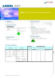
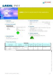
HP1 <strong>CO2</strong> Vaporiser<br />
The HP1 is a high pressure <strong>CO2</strong> electric vaporiser<br />
containing a 1 kW cartridge heating element. The unit is<br />
designed to be wall mounted and connected to either a<br />
single <strong>CO2</strong> syphon cylinder or to a manifold of cylinders<br />
by a high pressure hose or length of 3 /8 in o.d. high<br />
pressure copper tube.<br />
The HP1 vaporiser has an Rc1 /2 inlet connection and a<br />
BS341 Part 1 No. 8 <strong>CO2</strong> male outlet to take a suitable<br />
pressure reducing valve. The HP1 incorporates a safety<br />
bursting disc which ruptures at 190 bar.<br />
The heating element is controlled by a thermostat giving a<br />
gas outlet temperature of about 70°C. The thermostat is<br />
protected by a heat fuse. A neon light indicates when the<br />
heating element is in operation. The whole assembly is<br />
mounted in a splash proof steel casing.<br />
<strong>Air</strong> <strong>Liquide</strong> <strong>UK</strong> Limited Marketing Department, Station Road, Coleshill, Birmingham B46 1JY. England.<br />
Tel: +44 (0)1675 468837 Fax: +44 (0)1675 467022 Email: genenq.AL<strong>UK</strong>@airliquide.com 23017005<br />
R 3 /4<br />
HP1 <strong>CO2</strong> Vaporiser
HP3 <strong>CO2</strong> Vaporiser<br />
The HP3 is a 3 kW electric vaporiser designed <strong>for</strong> use with<br />
manifolded <strong>CO2</strong> syphon cylinders or with a <strong>CO2</strong> bulk<br />
storage tank. Liquid <strong>CO2</strong> enters the HP3 and is vaporised<br />
into gas. The <strong>CO2</strong> gas temperature is controllable over a<br />
temperature range of 50°C to 80°C. A pressure regulator<br />
should be fitted to control output pressure.<br />
The vaporiser is designed to be wall mounted. The inlet<br />
and outlet connections are Rc3 /8.<br />
The vaporiser requires a 230 V single phase supply. The<br />
3 off 1 kW elements are protected by a heat fuse.<br />
A pressure relief device must be fitted to protect the<br />
vaporiser against over pressure (see item 3).<br />
An interlocked switch is fitted to ensure electrical supply is<br />
disconnected when the door is opened.<br />
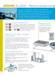
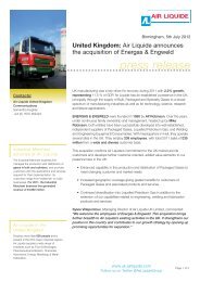
Typical Installation Diagram (with/without pressure reduction)<br />
Interconnecting Fittings<br />
www.uk.airliquide.com<br />
POWER<br />
ELEMENT 1 ELEMENT 2 ELEMENT 3<br />
HP3 VAPORISER<br />
DANGER<br />
400V<br />
2 3 4<br />
GAS SUPPLY<br />
VALVE<br />
LIQUID SUPPLY<br />
VALVE<br />
VENT VALVE<br />
HP3 <strong>CO2</strong> Vaporiser<br />
<strong>Air</strong> <strong>Liquide</strong> <strong>UK</strong> Limited Marketing Department, Station Road, Coleshill, Birmingham B46 1JY. England.<br />
Tel: +44 (0)1675 468837 Fax: +44 (0)1675 467022 Email: genenq.AL<strong>UK</strong>@airliquide.com 23017005<br />
1<br />
Item Description Part Number<br />
With pressure reduction<br />
1 Adapter R 3 /8 x 3 /8 in o.d. 2222.1302<br />
2 Nipple R 3 /8 x R 1 /2 2222.2007<br />
3 Either a) For bulk <strong>CO2</strong> – relief valve, 29 bar 2223.4801<br />
5<br />
6<br />
+ tee Rc 1 /2 equal 2222.2302<br />
or b) <strong>for</strong> cylinders – relief valve 103 bar 2223.5001<br />
+ tee Rc 1 /2 equal 2222.2302<br />
4 Nipple R 1 /2 male BS 341 No. 8/DIN 477 No. 6 2222.0101<br />
5 Copper tube 3 /8 in o.d. 2222.2401<br />
6 Regulator, 0-10 bar 7170.5379<br />
Bulk Kit Items 1, 2, 3a, 4 & 6 2224.0325<br />
Cylinders Kit Items 1, 2, 3b, 4 & 6 2224.0324<br />
Without pressure reduction<br />
Bulk Kit Items 1, 2, 3a & 4 2224.0327<br />
Cylinders Kit Items 1, 2, 3b & 4 2224.0326
HP6, HP12, HP18 & HP24<br />
<strong>CO2</strong> <strong>Vaporisers</strong><br />
The HP6 range of electric vaporisers is designed <strong>for</strong><br />
connection to <strong>CO2</strong> bulk storage tanks or large manifolds<br />
of <strong>CO2</strong> syphon cylinders. The vaporiser should be<br />
mounted on a raised stool (Part Number 2224.0423).<br />
When high <strong>CO2</strong> vaporisation rates are required, the HP6<br />
(6 kW) can be stacked up to 4 high and piped in series, to<br />
effectively create HP12 (12 kW), HP18 (18 kW) or HP24<br />
(24 kW) vaporisers. Each HP6 module is self contained,<br />
with separate temperature controller and contactor, which<br />
ensures that each element is only switched on to satisfy<br />
demand, hence saving energy.<br />
The inlet and outlet connections on the HP6 are 3 /4 in n.b.<br />
steel pipe compression fittings and are located at the back<br />
of the unit. Adapters terminating in R3 /4 are also provided.<br />
Each HP6 requires a 400 V, 3 phase, 4 wire power supply.<br />
Three 2 kW elements are cast within an aluminium heating<br />
block, each protected by a thermal heat fuse. A pressure<br />
relief device must be fitted to protect the vaporiser against<br />
over-pressure.<br />
The heat fuse elements are pure tin links which are<br />
connected in the line supply to the heating elements. In<br />
the event of an excessive temperature rise the electrical<br />
supply is interrupted.<br />
The temperature controller switches the 30 A 3-Phase<br />
contactor and is adjustable over a temperature range of<br />
50°C to 85°C.<br />
The normal operating temperature <strong>for</strong> the unit is<br />
65°C to 75°C.<br />
www.uk.airliquide.com<br />
Three 20 A miniature circuit breakers, located within the<br />
equipment, provide short circuit and overload protection.<br />
A lamp, mounted on the front panel, will signal when the<br />
main electrical supply is on. Three other lamps, each<br />
connected to an element, indicate when that element is<br />
functioning. An interlocked isolating switch is fitted to ensure<br />
the electrical supply is isolated when the door is opened.<br />
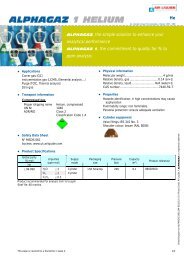
HP6 <strong>CO2</strong> Vaporiser<br />
HP24 <strong>CO2</strong> Vaporiser<br />
<strong>Air</strong> <strong>Liquide</strong> <strong>UK</strong> Limited Marketing Department, Station Road, Coleshill, Birmingham B46 1JY. England.<br />
Tel: +44 (0)1675 468837 Fax: +44 (0)1675 467022 Email: genenq.AL<strong>UK</strong>@airliquide.com 23017005
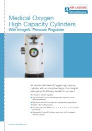
HP30 <strong>CO2</strong> Vaporiser<br />
The HP30 (30 kW) unit is normally used to vaporise liquid<br />
carbon dioxide taken from a bulk <strong>CO2</strong> storage vessel.<br />
The electrical components and heat exchange unit are<br />
housed in a robust steel cabinet which has been designed<br />
<strong>for</strong> easy maintenance. The vaporiser is fully protected<br />
against excess temperature and electrical overload.<br />
A pressure relief device must be fitted to protect the<br />
vaporiser against over-pressure.<br />
The vaporiser consists of four 7.5 kW heating units, each<br />
unit <strong>for</strong>med by cast aluminium alloy sections assembled<br />
and mounted in a thermally insulated steel cabinet. The<br />
outer sections in each heating unit have piping<br />
configurations cast within them to carry the liquid <strong>CO2</strong>.<br />
The low operating temperature and inherent high<br />
conductivity of the system together with the insulation<br />
provided ensure maximum efficiency with negligible<br />
heat loss.<br />
Layout<br />
967<br />
LIQUID CO 2<br />
INLET R 3/4<br />
160<br />
AMMETER<br />
www.uk.airliquide.com<br />
560<br />
730<br />
SUPPLY ON<br />
TRANSFORMER LAMP<br />
CO 2 VAPOUR<br />
OUTLET R 3/4<br />
890<br />
HEAT FUSES<br />
THERMOSTAT<br />
NEUTRAL TERMINAL<br />
2A HRC FUSE<br />
4A HRC FUSE<br />
LINK<br />
Thermal protection and control<br />
Heat Fuses<br />
Pockets are provided in the assembly <strong>for</strong> heat fuses.<br />
Heat fuse elements are connected in the supply line to<br />
the heating elements and in the event of an excessive<br />
temperature, the electrical supply is interrupted.<br />
Thermostat<br />
A pocket is also provided <strong>for</strong> a thermostat. This controls<br />
the 60 A TP contactor and is adjustable over a<br />
temperature range of 50°C to 85°C. The normal<br />
operating temperature <strong>for</strong> the unit is 65°C to 75°C.<br />
Heating Elements<br />
The system allows the heating elements to operate at high<br />
current density, providing high efficiency and long life. If an<br />
element fails, the element section can be removed and a<br />
replacement fitted. The electrical loading on the elements<br />
is indicated by an ammeter mounted on the front of the<br />
enclosure. A small neon indicator is provided adjacent to<br />
the ammeter to indicate when the supply is on.<br />
CONTACTOR TRANSFORMER PRESSURE<br />
Front Elevation RELIEF DIAPHRAGM Side Elevation<br />
700<br />
MAIN HEATER SWITCH<br />
<strong>Air</strong> <strong>Liquide</strong> <strong>UK</strong> Limited Marketing Department, Station Road, Coleshill, Birmingham B46 1JY. England.<br />
Tel: +44 (0)1675 468837 Fax: +44 (0)1675 467022 Email: genenq.AL<strong>UK</strong>@airliquide.com 23017005<br />
FRONT