
X-Cell Fury Tempest 3D Instruction Manual
Download - Miniature Aircraft USA
Download - Miniature Aircraft USA
- No tags were found...

You also want an ePaper? Increase the reach of your titles
YUMPU automatically turns print PDFs into web optimized ePapers that Google loves.
X-CELL LIMITED WARRANTY<br />
The warranty covers defects in material or workmanship or missing components to the original purchaser for 30 days<br />
from the date of purchase. Miniature Aircraft, USA will replace or repair, at our discretion, the defective or missing<br />
component. Defective components must be returned to us prior to replacement.<br />
Any part, which has been improperly installed, abused, crash damaged or altered by unauthorized agencies is<br />
not covered. Under no circumstances will the buyer be entitled to consequential or incidental damages. The<br />
components used in this kit are made from special materials designed for special applications and design<br />
strengths. We recommend that all replacement parts be original parts manufactured by Miniature Aircraft,<br />
USA, only to ensure proper and safe operation of your model. Any part used which were manufactured by any<br />
firm other than Miniature Aircraft, USA VOIDS all warranties of this product by Miniature Aircraft, USA.<br />
WARRANTY PROCEDURES<br />
Mail all warranty information within 15 days of original purchase date. If service is required, send the component<br />
in question (if not missing) together with a photocopy of your bill of sale and an accurate description of the<br />
problem and part. Ship components fully insured and prepaid. Miniature Aircraft, USA is not responsible for any<br />
shipping damages. We will, at our discretion, notify you of any costs involved, or ship it COD. You are required to<br />
pay all postage, shipping and insurance charges.<br />
--------------------------------------------------------------------------------------------------------------------------------------<br />
X-CELL FURY <strong>3D</strong> WARRANTY REGISTRATION<br />
Please print or type, filling in the information listed below and mail immediately<br />
Model No: ___________________ Serial No: __________________ Price Paid: ______________<br />
Owners Name: ______________________________________________ Age: ________________<br />
Address: ___________________________________________________ Phone________________<br />
City: _____________________________ State:_____________________ Zip:_______________<br />
Purchased From: __________________________________________________________________<br />
Dealer=s Address: _________________________________________________________________<br />
_______________________________________________________________________<br />
Comments:_____________________________________________________________________________<br />
--------------------------------------------------------------------------------------------------------------------------------------<br />
MINIATURE AIRCRAFT USA<br />
31713 Long Acres Drive<br />
Sorrento Fl 32776<br />
Phone (352) 383-3201<br />
FAX (352) 383-3204<br />
3
High Quality Synthetic Grease (M.A./USA p/n #4707)<br />
Light oil (Teflon type M.A./USA p/n #4801)<br />
Canopy finishing materials (described elsewhere)<br />
180-220 grit Awet or dry@ sandpaper<br />
AC@ clip pliers (both expanding and contracting types)<br />
Silicone glue<br />
1.3mm Allen Wrench (M.A. p/n #2964-3)<br />
The following are optional tools:<br />
Ball link installation tool (M.A./USA p/n #0529)<br />
5.0mm nut driver (M.A./USA p/n #2957-1)<br />
5.5mm nut driver (M.A./USA p/n #2957-2)<br />
7.0mm nut driver (M.A./USA p/n #2957-4)<br />
Flybar lock (M.A./USA p/n #0506-1)<br />
Flybar alignment kit (Expert models) (M.A./USA p/n #0510-1)<br />
Swashplate Alignment Tool (M.A./USA p/n #0513)<br />
Pitch gauge (M.A./USA p/n #0526)<br />
Custom hardened hex tools B 1.5mm (M.A./USA p/n #2984-1), 2.0mm (M.A./USA p/n #2984-2), 2.5mm<br />
(M.A./USA p/n #2984-3), 3.0mm (M.A./USA p/n #2984-5)<br />
The following items are required or useful in the operation of any R/C helicopter:<br />
Glow fuel specifically formulated for helicopter use with a percentage Nitro-methane content as suggested by your<br />
engine’s manufacturer or your personal preference (10% - 30% is the normal range). M.A./USA technicians can<br />
assist you in your selection.<br />
Fuel pump (We suggest M.A./USA p/n #4331 Electric pump or M.A./USA p/n #4333 <strong>Manual</strong> pump).<br />
12 volt electric starter.<br />
Starter extension adapter for 6.0mm diameter start shaft (we suggest the APro-Flex@ start system M.A./USA p/n<br />
#4684)<br />
12 volt battery (6.0 amp minimum).<br />
1.5 volt glow battery or glow driver and a connection method to ignite the glow plug. The most convenient<br />
connection method is using medium to large Aalligator@ clips. We suggest you contact M.A./USA to review other<br />
available connection options.<br />
Extra glow plugs. Glow plug selection should be of suitable heat range and quality to endure helicopter<br />
applications. Avoid Acheap@ plugs.<br />
Various selection of quality tools as used in the kit assembling steps.<br />
Frequency flag displaying your radio frequency and color code (included in radio)<br />
Academy of Model Aeronautics (A.M.A.) membership (those individuals not residing in the U.S.A. should join the<br />
modeling organization for their country). Membership in the Academy of Model Aeronautics allows you to fly at<br />
registered flying sites and events and provides liability insurance. Information is available by calling 1-800-435-<br />
9262 or by visiting the A.M.A website at www.modelaircraft.org.<br />
Premium grade fuel filter(s).<br />
5
ASSEMBLY INSTRUCTIONS<br />
Please take the time to review all instructions and drawings before building the kit. Each step will list bags, tools<br />
and parts required to proceed. Any position calling for the installation of steel threaded hardware into non-locking<br />
threads will refer to the addition of Blue Loctite thread locker (included). Any position using steel hardware into<br />
plastic will refer to the addition of slow Cyanoacrylate glue (CA) (not included) as a thread locker. Always clean<br />
the threads with alcohol and use the locking material sparingly.<br />
For individuals wishing to know, the following maximum torque values apply to metal to metal positions on the<br />
model:<br />
Bolt Size NCM (Metric) Inch/Pounds (U.S.)<br />
M3 40.0 3.5<br />
M4 70.0 6.2<br />
This information is provided only for interest and in no way indicates that a torque wrench is needed to<br />
successfully build the model.<br />
When installing hardware into plastic, be aware that a) threads are forming so hold the item straight while<br />
tightening and b) you must stop tightening as soon as the flange or head contacts the plastic surface.<br />
Frequently, the text will refer to items known as APEM@ nuts. These are M2.5 and M3.0 threaded steel inserts that<br />
are factory installed in both side frames and various frame channels used in the kit. They are non-locking and<br />
require the use of Blue Loctite on any related bolts or screws. Do not attempt to remove them and avoid overtightening<br />
hardware into them. They are quite secure with only minimal tightening and use of Blue Loctite.<br />
6
ASSEMBLY SEQUENCE SUMMARY<br />
Section: Subassembly:<br />
I<br />
II<br />
III<br />
IV<br />
V<br />
VI<br />
VII<br />
VIII<br />
IX<br />
X<br />
XI<br />
XII<br />
XIII<br />
XIV<br />
XV<br />
XVI<br />
XVII<br />
XVIII<br />
XIX<br />
Building the Rotor head<br />
Building the Left Main Frame<br />
Installing the Main Shaft, Main Gear and Front Tail Drive<br />
Building and Installing the Radio Support Assembly<br />
Installing the Right Main Frame, Bell cranks and Gyro Brackets<br />
Building and Installing the Landing Gear<br />
Installing the Clutch, Fan, and Engine Assembly (Including Guidelines for Engine and Exhaust Selection).<br />
Building and Installing the Fuel Tank Assembly<br />
Installing the Swash plate, Washout Unit and Rotor head Assembly<br />
Building the Tail Rotor Assembly<br />
Building the Tail boom Assembly, Boom Supports and Installation onto the Main Mechanics<br />
Installing the Radio System and Pushrods<br />
Preparing the Canopy<br />
Rotor Blade Selection<br />
Final Mechanical and Electronic Set-up<br />
Final Inspection<br />
Pre-Flight Information<br />
Starting and Stopping Procedures<br />
First Flight Adjustments<br />
7
I. BUILDING THE ROTOR HEAD<br />
Bags Required: #1A through #1G and Bag #11A<br />
Tools or materials required:<br />
Small Phillips screwdriver<br />
Small hammer<br />
Solvent (thinner or alcohol)<br />
Loctite B Blue and Green<br />
Slow cyanoacrylate glue (CA)<br />
M1.3, 1.5, 2.5 and 4.0 Allen tools<br />
AQ-Tip@ cotton swabs or tissue<br />
Needle nose pliers or forceps<br />
A few inches of masking tape<br />
3/8@ or similar socket with an O.D. of 14.0 B16.0mm<br />
Grease<br />
Step 1: Installing the Flybar and Control Arms<br />
Parts Required: Bag #<br />
2 #0840-7 4mm Washer 1B<br />
1 #123-20 Flybar Support Tube Assembly 1A<br />
1 #0566-1 Flybar 11A<br />
2 #0109 M3 x 8 Threaded Balls 1B<br />
2 #0572-7 Aluminum Standoff 1B<br />
2 #122-03 Flybar Control Arm 1B<br />
2 #0051 M3 x 3 Socket Set Screws 1B<br />
2 #0063 M3 x 10 Socket Head Bolts 1B<br />
2 #0067 M3 x 14 Socket Head Bolts 1B<br />
2 #122-18 Threaded s/s Spacer 1B<br />
Refer to Drawings #1A and #1B<br />
A. Select two #122-03 Flybar Control Arms, two #0063 M3 x 10 Socket Head Bolts, two #122-18 Threaded s/s<br />
Spacers, two #0572-7 Aluminum Standoffs, and two #0109 M3 x 8 threaded balls. Assemble each flybar<br />
control arm per the drawing. Tighten securely using Blue Loctite.<br />
B. Note: Each Flybar Control Arm #122-03 contains three optional positions. Generally the center hole will be<br />
used, but if increased paddle control is desired, the inside hole may be used or if less control is desired, use<br />
the outer most hole.<br />
C. Study the drawing for the orientation of each flybar control arm assembly. Select the Flybar #0566-1 and<br />
insert it into the flybar support tube assembly bearings on the rotor head block. Visually center the flybar.<br />
Select one #0840-7 4mm Washer and one flybar arm assembly. Slide the washer followed by the arm onto the<br />
flybar, up to the bearing. Repeat this process on the opposite side. Apply Blue Locktite to two #0051 M3 x 3<br />
Socket Set Screws and install one into each control arm. Carefully measure the assembly until the lengths are<br />
equal and no freeplay exits in and out of the head block. Align each flybar control arm until they are level<br />
with each other, then securely tighten each set screw.<br />
8
D. Select two #0067 bolts and temporarily thread each into holes provided near the base of the head block. Note<br />
that even though the holes are threaded full depth, the bolts install from the side closest to the slot at each<br />
corner. Do not tighten until Section IX , Step 2F.<br />
Step 2: Installing the Bell Hiller Mixers<br />
Parts Required: Bag #<br />
2 #0113 M3 x 10.5 Threaded Double Ball (long threads) 1C<br />
2 #0597-1 M3 x 0.126” x 0.187” Brass Spacer 1C<br />
2 #0109 M3 x 8 Threaded Ball 1C<br />
2 #0050-1 M2.5 x 3 Socket Set Screws 1C<br />
2 #123-24 Pitch Arms 1C<br />
2 #0597-3 M3 x 0.186” x 0.188” Brass Spacer 1C<br />
2 #0115 M3 x 10.5 Threaded Ball 1C<br />
2 #123-26 Bell Hiller Mixers 1C<br />
4 #106-02 M3 x 7 x 3 Flanged Ball Bearings 1C<br />
2 #0091 M3 x 16 Phillips Bolt 1C<br />
2 #0562-1 M3 x .09 Shim Washer 1C<br />
Refer to Drawing #1C.<br />
A. Press one #106-02 M3 x 7 x 3 Flanged Ball Bearing into each #123-26 Bell Mixer. It is recommended that<br />
the bearing be installed first in the same side of each mixer. A light amount of Green Loctite is mandatory on<br />
the outer race of each bearing. Insert one #0597-3 Brass Spacer into each bearing cavity opposite the<br />
installed bearing followed by another #106-02 bearing in the opposite side of the bearing cavity in the bell<br />
mixer.<br />
B. Install one #0109 Threaded Ball and one #0115 Threaded Ball into each Bell Mixer, use Blue Locktite,<br />
tighten securely.<br />
Notes About Mixing Ratios and Setup:<br />
The Bell Mixers, Flybar Tube, and Pitch Arms offer various mixing ratio options. The following guides<br />
will help you select your options.<br />
Bell Mixers: The Bell Mixers may be installed on the Pitch Arms in one of two positions:<br />
Position 1: Raised bearing boss side facing away from the Pitch Arm<br />
Position 2: Raised bearing boss side facing Pitch Arm<br />
Flybar Tube: The Flybar Tube offers two threaded hole positions on each end of the tube for location of<br />
the Double Threaded Balls:<br />
Position 1: Inside Holes<br />
- Increased Flybar Input<br />
- Increased Pitch to Flybar<br />
- Identical ratio as Standard Extreme rotorhead<br />
Position 2: Outside Holes<br />
- Medium Flybar Input<br />
9
- Medium Pitch to Flybar<br />
The following Mixing Ratios are possible with the combination of positions chosen:<br />
Bell Mixer Mounting<br />
Flybar Tube Control Ball Location<br />
Location Inside Hole Outside Hole<br />
Position 1 1:0.61 1:0.56<br />
Position 2 1:0.62 1:0.58<br />
Table 1: Head Input Mixing Ratios<br />
Pitch Arms: Each Pitch Arm has three threaded hole positions for mounting the Bell Mixers. The center<br />
hole is zero offset, the left hole (nearest the main shaft) is negative offset, the right hole (nearest the blade<br />
grip) is positive offset:<br />
Position 1: Zero Offset<br />
- Neutral corrections due to wind influence<br />
Position 2: Positive Offset<br />
- Slightly improved high-speed tracking<br />
Position 3: Negative Offset<br />
- Improved hovering characteristics in the wind<br />
Note: The Pitch Arm offset desired is a pilot preference. This may vary due to combinations of blades<br />
and head speeds chosen. Choice by trial is recommended.<br />
C. Select two #0113 Threaded Double Balls and two #0597-1 Brass Spacers. Install a Brass Spacer on each<br />
Threaded Double Ball and apply Blue Locktite to the exposed threads. Install one prepared Threaded Double<br />
Ball into the chosen position in the Flybar Tube. Repeat for the opposite end of the Flybar Tube. Tighten<br />
securely.<br />
D. Using Blue Locktite, install each Bell Mixer onto the #123-24 Pitch Arms with one #0091 M3x16 Phillips<br />
Bolt and one #0562-1 M3x0.09” Shim Washer. Each unit should pivot freely after tightening. As a safety,<br />
install one #0050-1 M2.5x3 Socket Set Screw into the top side of each Pitch Arm at the chosen offset<br />
mounting hole location of the Bell Mixers.<br />
10
Step 3: Installing the Upper Head Block Assembly<br />
Parts Required:<br />
Bag#<br />
1 #122-14 Upper Head Block 1A<br />
1 #122-17 Head Button 1D<br />
4 #0064 M3 x 8 Button Head Socket Head Bolt 1D<br />
2 #0062 M3 x 10 Flat Head Bolt 1D<br />
1 Pre-assembled Lower Block Assembly from Step 1<br />
2 #0687 M3 x 0.086” x 0.158” Steel Spacer 1D<br />
Refer to Drawing #1D<br />
A. The upper head block #122-14 is symmetrical by design, therefore it may be installed on either side. Slide the<br />
upper head block onto the pre-assembled lower block assembly. It may be necessary to lightly tap both<br />
components together. Use a plastic or rubber hammer. If any metal device is used protect the parts with a<br />
piece of hard wood. Secure together with four #0064 M3 x 8 Button Head Socket Head Bolts. Use Blue<br />
Loctite.<br />
B. Install the #122-17 head button to the top of the lower head block #122-15 using two #0062 M3 x 10 Flat<br />
Head Bolts and two #0687 Steel Spacers. Use Blue Loctite.<br />
Step 4: Assemble the Main Blade Mounts and Head Axle<br />
Parts Required: Bag #<br />
2 #0011 M5 Washer 1E<br />
2 #0023 M5 Locknuts 1E<br />
2 #0060 M3 x 5 Socket Head Bolt 1E<br />
4 #0061 M3 x 8 Socket Head Bolt 1E<br />
2 #0086 M5 x 12 Flanged Socket Head Bolt 1E<br />
4 #0319 M8 x 16 x 5 Ball Bearing 1E<br />
2 #0329 M8 x 13 x .25 Shim 1E<br />
2 #0331 M8 x 13 x .50 Shim 1E<br />
2 #0426 M8 x 13 x .10 Shim 1E<br />
2 #0840-10 M 8 x 12 x .80 Spacer 1E<br />
2 #0840-12 3-piece Thrust Bearing 1E<br />
4 #0844-2 70-D Rubber O-rings 1E<br />
2 #0848-4 Aluminum retainer sleeves 1E<br />
2 #0848-3 M8 x 12 x 2.0 Hinge Ring 1E<br />
1 #122-02 Head Axle 1E<br />
2 #122-11 Machined Main Blade Mounts 1E<br />
2 #122-12 M5 Main Blade Bolts 1E<br />
2 #122-13 M5 Fiber Blade Spacers 1E<br />
Refer to Drawings #1E, #1F<br />
11
NOTE: Two different hardness of o-rings dampeners and three sets of shim thickness are included. The specific<br />
dampening may vary depending on the main blades chosen or your personnel flying style. We suggest starting with<br />
the o-rings and shims described in the following building sequence.<br />
-Std. Dampening 4 70-D O-rings (#0844-2)<br />
2 (0.050”) Shims (#0331)<br />
-Stiffer Dampening 2 70-D O-rings (#0844-2)<br />
2 80-D O-rings (#0844-)<br />
Various combinations of the #0329, #0331, or #0426 Shims<br />
A. Select one #122-02 Head Axle, two #0844-2 70-D Rubber O-rings. (Do not lubricate the o-rings with any<br />
oil, grease or Vaseline. If aid is needed in installing the O-rings, use only liquid which will evaporate<br />
such as window cleaner). Center the Head Axle in #122-14 upper head block. Slide two #0844-2 70-D<br />
Rubber O-rings on each side of the Head Axle. Push the O-rings into the upper head block while centering<br />
the Head Axle.<br />
B. On one end of the Head Axle assemble the following components in the sequence shown.<br />
1) one #0331 M8 x 13 x 0.5 Shim<br />
2) one #0848-3 Hinged ring (cupped side facing the o-rings)<br />
3) one #0319 M8 x 16 x 5 Ball Bearing<br />
4) one #0848-4 Aluminum retainer sleeve (counter-bore side facing the bearing)<br />
5) one #0840-12 Thrust bearing ( 3 pieces )<br />
Special Note: The thrust bearing will contain one outer ring that has a smaller I.D. hole than the<br />
other outside ring. Identify this feature before proceeding. Install the larger I.D. bearing race<br />
with the groove side away from the retainer sleeve. Apply grease to the groove. Next slide the<br />
ball/cage into position, using more grease. Slide the remaining small I.D. bearing race into<br />
position with the groove facing the ball/cage.<br />
6) one #0840-10 M8x12x0.80 Spacer<br />
7) one #0319 M8x16x5 Ball Bearing<br />
8) one #0011 M5 Washer<br />
9) one #0086 M5x12 Flanged Socket Head Bolt<br />
NOTE: Sparingly apply Blue Loctite to the threads and install into the Head Axle.<br />
Tighten only finger tight at this time.<br />
12
C. Repeat step AB@ on the opposite end of the Head Axle. Tighten both #0086 bolts using two 4mm Allen<br />
wrenches.<br />
D. Slide one #122-11 blade mount into position on the bearing assembly and align the holes with those of the<br />
aluminum retainer sleeve #0848-4. On the side of the blade mount with only one hole, install one #0060 M3 x<br />
5 Socket Head Bolt. Only finger tighten at this time.<br />
E. Select two Preassembled Pitch Arms from Step 1C and four #0061 M3x8 Socket Head Bolts. Study the<br />
drawings and position the assembled pitch arms into the milled groove side of the #122-11 Machined Main<br />
Blade Mounts. Using two #0061 M3x8 Socket Head Bolts on each arm. Use Blue Loctite. Note: The pitch<br />
arm is a light press fit. Start to thread one or both #0061 bolts a few turns with a small amount of Blue<br />
Loctite. Using a plastic tool handle or a wooden block, tap the pitch arm into place. Moderately tighten both<br />
#0061 bolts in each arm. Remove the previously installed #0060 bolt, add Blue Loctite and moderately<br />
tighten.<br />
F. Temporarily install the two #0086-2 M5 Blade Bolts, two #0023 M5 Locknuts, and two #122-13 M5 Fiber<br />
Blade Spacers.<br />
Step 5: Assembly of the Flybar Paddles<br />
Parts Required: Bag #<br />
2 #0871-5 Sport Paddles 1G<br />
Refer to Drawing #1G<br />
Measure 22.0mm inward from each flybar end and mark with tape. The flybar is self-threading into each paddle<br />
and the goal is to have each paddle level to the other and the flybar control arms. Note, if your chosen option was<br />
to angle the flybar arms downward then the visual line for alignment will be a horizontal line drawn through and<br />
connecting each ball on each #0307 control arm. A useful tool for aligning the paddles is the #0510-1 paddle<br />
gauge kit. Slow CA glue or epoxy is used as a paddle-locking device, allowing sufficient cure time to simplify<br />
aligning the component. Install each paddle as indicated and remove the marking tape. If all steps were accurately<br />
performed then it should be evident that by holding the head vertical and releasing the flybar the paddles will<br />
appear balanced. If not, then a small piece of vinyl tape can be applied to the “light” paddle. It is also possible to<br />
fine-tune the balance by lightly sanding the tip of the “heavy” paddle.<br />
13
II. BUILDING THE LEFT MAIN FRAME<br />
Bags Required: #2A, #2B, and #<strong>3D</strong><br />
Tools or Materials Required:<br />
M2.5 Allen Tool<br />
M5.5 (7/32@) flat wrench<br />
M7.0 (9/32”) flat wrench<br />
Assemble the Left Main Frame<br />
Parts Required: Bag #<br />
1 #0064 M3 x 8 Button Head Socket Head Bolt 2B<br />
2 #0009 M3 Washer 2B<br />
2 #0019 M3 Locknut 2B<br />
3 #0060-1 M3x6 Socket Head Bolt 2B<br />
7 #0061 M3x8 Socket Head Bolt 2B<br />
4 #0063 M3x10 Socket Head Bolt 2B<br />
1 #0089 M3x10 Hex Bolt 2B<br />
1 #0169 Bell Crank Pivot Stud 2B<br />
1 #120-44 CNC Machined Anti-rotation Guide 2B<br />
1 #115-10 Vertical Rear Channel w/Bearing 2A<br />
1 #115-12 Vertical Front Channel 2A<br />
1 #115-18 Lower Main Shaft Bearing Block 2B<br />
4 #115-20 Frame Spacers 2B<br />
1 #120-8 Main Shaft / T/R Drive Block Assembly 2B<br />
1 #120-12 Upper Main Shaft Bearing Block 2B<br />
1 #123-28 G-10 Left Main Frame 2A<br />
1 #122-27 Rear Canopy Hex Spacer Mount 2B<br />
1 #120-10 Main Shaft <strong>3D</strong><br />
Refer to Drawing #2A<br />
A. Select the #123-28 G-10 Left Main Frame, one #115-10 Vertical Rear Channel, one #122-27 Hex Spacer, one<br />
#0089 M3 x 10 Hex Bolt, one #0061 M3 x 8 Socket Head Bolt, and one #0019 M3 Locknut. Orient the Left<br />
Main Frame and the Rear Vertical Channel as shown. Install the required hardware. Use Blue Loctite on the<br />
#0089 Hex Bolt. Tighten securely.<br />
B. Select one #0169 Bell Crank Pivot Stud and one #115-20 Frame Spacer. Note: The position for the Bell<br />
Crank Pivot Stud is on the outside of the main frame. Install both components. Tighten securely using Blue<br />
Loctite.<br />
C. Select the #120-44 CNC Machined Aluminum Swashplate Anti-rotation Guide and install the swash plate<br />
guide assembly onto the Left Main Frame using two #0060-1 M3 x 6 Socket Head Bolts and two #0009 M3<br />
Washers, align in a vertical position and tighten securely. Use Blue Loctite.<br />
14
D. Install the #115-12 Vertical Front Channel using one #0061 M3 x 8 Socket Head Bolt, one #0063 M3 x 10<br />
Socket Head Bolt and one #0019 M3 Locknut. The open side of the channel faces forward. Temporarily<br />
install the #0063 M3x10 Socket Head Bolt into the fifth hole from the bottom of the frame in the location for<br />
the channel as shown. Temporarily lightly tighten the bolt so the channel can be aligned at the bottom. Align<br />
all holes and install one #0061 Socket Head Bolt with one #0019 M3 Locknut into the hole, fourth hole up<br />
from the bottom. Tighten the bolt and nut securely.<br />
E. Install the #120-12 Upper Main Shaft Bearing Block (hump side upward) using two #0063 M3x10 Socket<br />
Head Bolts using Blue Loctite. Do not fully tighten.<br />
F. Install the #120-8 Main Shaft/Tail Rotor Drive Block Assembly as shown using one #0060-1 M3 x 6 Socket<br />
Head Bolt, one #0061 M3 x 8 Socket Head Bolt, and one #0064 M3 x 8 Button Head Socket Head Bolt. Use<br />
Blue Loctite. Do not fully tighten.<br />
G. Install the #115-18 Lower Main Shaft Bearing Block as shown (full diameter of the bearing facing down)<br />
using one #0061 M3 x 8 Socket Head Bolt and one #0063 M3 x 10 Socket Head Bolt. The #0063 Socket<br />
Head Bolt will be removed later. Add Blue Loctite to the #0061 Socket Head Bolt only.<br />
H. Remove the #120-10 Main Shaft from bag <strong>3D</strong>. Slide it down through all three bearing blocks. Securely<br />
tighten all the bolts except the #0063 Socket Head Bolt, installed in the #115-18 Lower Main Shaft Bearing<br />
Block. Remove the Main Shaft.<br />
I. As per the drawing, install three #115-20 Frame Spacers in the inner front of the main frame using three<br />
#0061 M3 x 8 Socket Head Bolts. Tighten securely using Blue Loctite.<br />
15
III. INSTALLING THE MAIN SHAFT, MAIN GEAR AND FRONT TAIL DRIVE<br />
Bags Required: #3A, #3B, #3C, #7D<br />
Tools or Materials Required:<br />
M1.5, 2.0 and 2.5 Allen tools<br />
M5.5 flat wrench<br />
Tri Flow #4801 or similar Teflon oil<br />
Step 1: Installing the Front Tail Rotor Drive Gear and Shaft<br />
Parts Required: Bag #<br />
3 #0051 M3x3 Socket Set Screws 3A<br />
1 #0232 15 Tooth Bevel Gear 3A<br />
1 #0237 M5 Retaining Collar 3A<br />
1 #120-9 Front Transmission Shaft 3A<br />
Refer to Drawing #3A<br />
A. Select one #120-9 Front Transmission Shaft, one #0237 M5 Retaining Collar, and one #0232 15 Tooth Bevel<br />
Gear. Examine the drawing and note the orientation of these parts. Insert the #120-9 Front Transmission<br />
Shaft from the rear of the main frame through the bearing in the #115-10 Vertical Rear Channel. With 25-<br />
30mm exposed in front of the bearing, slide the #0237 M5 Retaining Collar, followed by the #0232 Bevel<br />
Gear, onto the shaft.<br />
B. Select one #0051 M3x3 Socket Set Screw, apply blue Loctite and partially thread into the #0237 M5<br />
Retaining Collar. Push the shaft forward into the #120-8 Front Transmission Block and bearing. Apply<br />
forward pressure on the white Delrin portion of the #120-9 Front Transmission Shaft while pressing rearward<br />
on the #0237 M5 Retaining Collar. Tighten the #0051 M3x3 Socket Set Screw within the collar. Check to<br />
see that no end-play exists in the shaft. If there is end-play, then reposition the collar.<br />
C. Select two #0051 M3x3 Set Screws. Note the #120-9 Front Transmission Shaft has a Aflat@ for a set screw<br />
securing the #0232 Bevel Gear. Select one #0051 M3x3 Set Screw and install it into the gear, tightening it<br />
enough to be certain it has engaged the Aflat@ and the gear can be moved for final positioning. Set the final<br />
gear position after the main gear is installed, observing the rule that the bevel gear be centered within the main<br />
gear. Check this for a full rotation of the main gear. Always remember to install the remaining #0051 M3x3<br />
Socket Set Screw and double check the contact of the first set screw within the Aflat@ provided. Use Blue<br />
Loctite on each set screw.<br />
16
Step 2: Assemble the Constant Drive Autorotation Upper Section<br />
Parts Required:<br />
Bag#<br />
8 #0088-1 M3x5 flat head screws 3B<br />
1 #0866-5 70-Tooth Upper Bevel Gear 3B<br />
1 #0866-6 Upper gear mounting base w/main shaft sleeve 3B<br />
Refer to Drawing #3B<br />
Select eight #0088-1 M3x5 Flat Head Screws and prepare each with Blue Loctite. Select the #0866-5 Bevel Gear<br />
and #0866-6 Mounting Base. Press the mounting base downward into the upper surface of the bevel gear,<br />
aligning the holes as you proceed. From the underside, install the eight #0088-1 M5x3 Flat Head Screws,<br />
tightening them a little at a time in a Astar@ pattern. Tighten all with light torque.<br />
Step 3: Install the Outer Main Gear onto the Autorotation Hub<br />
Parts Required:<br />
Bag#<br />
1 Main Gear 7D<br />
4 #0088 M3x8 Flat Head Socket Bolts 3C<br />
2 #0866-10 M14.0-20.0x0.2 shim rings 3C<br />
1 #0866-11 M14 Teflon O-rings 3C<br />
1 #0866-4 Lower Housing w/ sprag bearing 3C<br />
Refer to drawings #3C and #<strong>3D</strong><br />
A. Select four #0088 bolts and prepare with Blue Loctite. Select the outer main gear (p/n appropriate to your<br />
kit’s gear ratio) and note the four countersunk holes on the upper surface. Only the countersunk holes will be<br />
utilized. Press the gear atop the upper housing, align the countersunk holes, install the four bolts and tighten<br />
with light torque.<br />
B. Select one #0866-10 shim ring and apply a little grease to each side. Set this ring atop the Oilite bushing<br />
(visible at the top of the upper housing, protruding through the main gear).<br />
C. Select another #0866-10 shim ring, apply grease and slide upward to meet the gear mount. Select one #0866-<br />
11 Teflon O-ring and install it next to the shim ring. Set the main gear/sprag housing assembly upright on the<br />
table. Insert the upper gear/sleeve assembly downward into the sprag clutch. When it makes contact, rotate<br />
the upper assembly slightly clockwise while lightly pressing downward. When it drops inward about 5.0mm<br />
(easily noticed as you rotate and push downward) lift the combined parts off the table. Hold them inverted at<br />
about a 45 degrees angle and apply a liberal amount of Tri-flow oil to that portion of the sprag clutch that is<br />
visible just inside the lower Oilite bushing in the lower hub. Rotate the unit as you apply more oil. The unit<br />
will hold about 7-8cc (1/4 ounce) of oil. When oiling is completed, press the upper gear fully into the lower<br />
gear and wipe away any excess oil.<br />
Note: never force the main shaft sleeve into the sprag clutch. If it does not insert easily while rotating,<br />
look from beneath the sprag to be sure that the cogs look uniformly positioned. They are only retained<br />
by an outer spring and it is possible to dislocate one during insertion. If necessary, remove the sprag<br />
clutch from the housing and it will return to its proper configuration.<br />
17
Step 4: Installing the Main Shaft and Main Gear/Autorotation Assembly<br />
Parts Required:<br />
Bag#<br />
1 #0057 M4x4 socket head set screw <strong>3D</strong><br />
2 #0059-1 M2.5x6 Socket Head Bolts <strong>3D</strong><br />
1 #120-10 Main shaft <strong>3D</strong><br />
1 #0840-6 M3x20 dowel pin <strong>3D</strong><br />
1 #0865-6 M10.1x15.8x0.1 shim ring <strong>3D</strong><br />
1 #0865-7 M10.1x15.8x0.2 shim ring <strong>3D</strong><br />
1 #0866-10 M14.0x20.0x0.2 shim ring <strong>3D</strong><br />
1 #0866-11 M14 Teflon o-ring <strong>3D</strong><br />
1 #0866-12 Retaining collar (black) <strong>3D</strong><br />
1 #0866-13 M14.0x20.20x0.1 shim ring <strong>3D</strong><br />
2 #0875-1 Split type main shaft collars <strong>3D</strong><br />
1 #115-22 M10.1x11.1x7.8 brass tube <strong>3D</strong><br />
Refer to drawings #<strong>3D</strong> and #3E<br />
A. Select the #120-10 main shaft. NOTE: The main shaft must be installed per the drawing. Apply a little light<br />
oil to a cloth and briskly wipe-down the shaft. This will remove the protective coating. It is suggested that a<br />
trial fit of the main shaft be preformed prior to assembling the main shaft components. It may be necessary to<br />
loosen the lower block for alignment, re-tighten with the main shaft in place. As noted above, insert the<br />
correct end of the main shaft into the upper main shaft bearing block at the top of the mainframe. Slide it<br />
through so that 20-30mm is exposed below the bearing block.<br />
B. Select two #0875-1 ASplit@ type main shaft collars. Examine the collars. One end of each collar has a flat<br />
surface with a .30mm raised step near the bore. This end is always to face a ball bearing. Using this criteria,<br />
slide two split collars onto the main shaft exposed below the upper bearing block. The upper collar should<br />
have it=s flat surface (with step) facing up to the underside of the upper bearing block and the lower collar<br />
should Aface@ the bearing in the lower block. Slide the main shaft further downward into and through the<br />
lower bearing block until about 6.0 B 7.0mm is exposed below.<br />
C. NOTE: The following orientation and selection of parts is considered the Anormal@ parts required. Parts Bag<br />
<strong>3D</strong> will also contain two sizes of special shim rings (#0865-6 and #0865-7) which will only be used to finetune<br />
an Aunusual@ fit and would only be utilized between the #115-22 spacer washer and the autorotation unit.<br />
Select the #115-22 brass tube. Slide the tube onto the main shaft and up inside the lower bearing block.<br />
Approximately 1.0mm will be exposed below the bearing block.<br />
D. Select the previously assembled autorotation, the #0840-6 dowel pin, the #0866-10 shim ring, the #0866-11<br />
Teflon o-ring, the #0866-12 collar and the #0866-13 shim ring. It should now be determined which (or both)<br />
shim rings (#0866-10 and/or #0866-13) are required. Invert the autorotation assembly and note the Oilite<br />
bushing exposed at the base of the housing. A shim ring should always be placed next to this bushing. As a<br />
trial, install the #0866-10 M14.0x20x0.2 shim ring followed by the Teflon o-ring and the black retaining<br />
collar. Temporarily insert the #0840-6 dowel pin through the collar (large I.D. hole) and into the autorotation<br />
sleeve. Rotate the outer main gear against the inner and check smooth rotation. Move the gear up and down<br />
between the upper gear and the remaining collar. The desired situation is to have the gear rotate freely but<br />
have very little up/down play. If it is too tight, substitute shim ring #0866-13 for the #0866-10. If it is too<br />
loose, add shim ring #0866-13. If there is no free play and the rotation is with very light friction, it can remain<br />
as is since the Teflon O-rings will break-in quickly. It should be noted that there is no operational problem or<br />
risk even if the unit develops as much as 0.5mm of free play (at your option the O-rings could be replaced or a<br />
shim added). When the correct shim(s) has been determined, remove the dowel pin, the retaining collar, the<br />
18
O-rings, and the shim(s). Apply a little grease to each side of the shim(s) and reinstall all items except the<br />
dowel pin.<br />
NOTE: Concerning step AF@ below, it may be necessary to loosen the lower main shaft block #115-18 to<br />
allow the main shaft to slide into the bearing easily. Re-tighten the bolts after the main shaft has been<br />
tightened.<br />
E. Slide the autorotation unit into position and slide the main shaft downward. Align the holes within the #0866-<br />
12 retaining collar, the sleeve on #0866-6 and the lower main shaft hole. Note: that the #0866-12 retaining<br />
collar has one large hole and one small hole. The large hole is for insertion of the #0840-6 M3x20 dowel pin<br />
and the subsequent #0057 M4x4 socket set screw. The small hole is for removal of the pin using a 1.5mm<br />
Allen tool or similar device. Insert the #0840-6 dowel pin as shown in drawings <strong>3D</strong>. The pin should easily<br />
slide in far enough to allow installation of the set screw. If not, then there are two possible causes and various<br />
steps to cure the problem:<br />
1. The pin may not insert fully due to an obstruction within the collar. Remove the collar and trial fit<br />
the pin. Look for any metal debris lodged in the Asmall hole@ side of the collar. If any exist, use a<br />
1.5mm tool to push the debris out.<br />
2. The pin may not insert fully due to misalignment of the holes in the related parts. The main shaft<br />
hole is suspect here. The easiest solution is to run a sharp 0.120” (3.0-3.1mm or #31) Drill bit into<br />
the assembled retaining collar, sleeve and main shaft. This will deburr any offending hole and will<br />
not harm anything. The drill will stop automatically as it reaches the small hole on the opposite side<br />
of the collar and is too small to harm the M4 threads at the inlet.<br />
Reinstall the pin followed by the #0057 M4x4 set screw with a very small amount of Loctite (on the set screw<br />
only).<br />
Note: The sprag bearing should be cleaned and re-lubricated periodically (approximately every 50-75 fights).<br />
F. The main shaft must now be adjusted and secured at the middle bearing block. Select one #0059-1 M2.5x6<br />
socket head bolt, apply a little Blue Loctite and insert an M2 Allen tool. Rotate the lower main shaft split<br />
collar (#0875-1) for access to the threaded hole and install the bolt, leaving it loose and the tool in place. Pull<br />
upward on the main shaft while pressing downward on the split collar. Tighten the bolt. Check the gear mesh<br />
during a full rotation of the main gear. If the gear mesh is Anotchy@ and tight throughout the 360 degree<br />
rotation (and the tail rotor bevel gear is confirmed to be correctly positioned as per Section III Step 1C) then<br />
an adjustment is required. This can be accomplished by either adding a shim ring as per section III step 5D or<br />
slight repositioning of the #0232 bevel gear. The shims are the preferred method. If the gear mesh has only<br />
one or two small tight spots during a full rotation, nothing is required as they will break-in quickly.<br />
G. To avoid loss and prepare for final adjustment during a later step, select the remaining #0059-1 M2.5x6<br />
socket head bolt and temporarily install it in the upper split collar, move the unit up to the upper bearing block<br />
and lightly tighten.<br />
19
IV. BUILDING AND INSTALLING THE RADIO SUPPORT ASSEMBLY<br />
Bags Required: #4A, #4B<br />
Tools or Materials Required:<br />
M2.0 and 2.5 Allen tools<br />
M5.5 flat wrench (7/32@)<br />
Assemble and Install the Radio Support<br />
Parts Required: Bag #<br />
4 #0019 M3 hex locknuts 4B<br />
2 #0064 M3x8 button head bolts 4B<br />
1 #0089 M3x10 flat hex head bolt 4B<br />
2 #0840-31 M3x16 button head bolts 4B<br />
1 #106-41 Canopy Standoff 4B<br />
1 #115-24 Horizontal channel 4A<br />
1 #123-32 Tank plate 4A<br />
1 #115-28 Radio/battery plate 4A<br />
1 #115-30 16.0x305.0mm red Velcro 4A<br />
2 #115-32 Plastic spacers 4B<br />
Refer to Drawings #4A and #4B.<br />
A. Select the #115-24 Horizontal Channel. Being a Au-shaped@ channel, we=ll consider the bottom to be the flat<br />
side. Select the #123-32 Tank Plate. Two-sided adhesive tape has already been applied. This side will be the<br />
Abottom@ side. Review Drawing #4A to determine what is Afront@ and Arear@ for each part. Select two #0064<br />
M3x8 Button Head Bolts and two #0019 M3 Hex Locknuts. The two bolts should enter the tank plate from<br />
the bottom (Atwo-sided adhesive tape side@) up through the flat side of the #115-24 Horizontal Channel,<br />
followed by two #0019 M3 Hex Locknuts from above. Tighten both securely.<br />
20
B. Select the #115-28 Radio/battery Plate, the #115-30 Velcro Strip, two #0840-31 M3x16 Button Head Bolts,<br />
two #115-32 Plastic Spacers and two #0019 M3 Hex Locknuts. At this time, it is suggested to make a<br />
determination of final battery position for correct model C.G. Two positions are possible on the radio/battery<br />
plate. In general, you=ll want to locate the plate in the forward position using the most narrow bolt spacing.<br />
C. The #115-28 radio/battery plate is reversible so either side can be considered the top. Holding the Velcro<br />
strip firmly against the bottom of the radio/battery plate (with the three holes aligned) insert two #0840-31<br />
M3x16 button head bolts from the topside of the plate and through the Velcro strip. Select two #115-32<br />
plastic blocks and slide each onto an exposed bolt. Position this assembly onto the front end of the #115-24<br />
horizontal channel (the side opposite the previously installed tank plate and the open part of the Au-channel@<br />
upward). The plastic blocks will sit inside the open side of the channel. Install and tighten two #0019 M3 hex<br />
locknuts onto the bolts and against the bottom Aflat@ side of the channel.<br />
D. Select one #106-41 canopy stand-off and one #0089 M3x10 flat hex head bolt. The sides of the #115-24<br />
horizontal channel each have three holes. Two are with PEM nuts and one, at approximately center, is open.<br />
From inside the u-channel, insert one #0089 M3x10 flat hex head bolt so it protrudes out of the Aleft side@<br />
open hole. Examine the left main frame. In the lower front section, the left frame has three holes which<br />
correspond to those on the left side of the horizontal channel. Apply Blue Loctite to the previously inserted<br />
#0089 bolt and insert it with the horizontal channel into the furthermost forward hole in the main frame. From<br />
outside the main frame, install one #106-41 canopy stand-off onto the #0089 bolt. Align the remaining two<br />
holes and tighten the bolt into the stand-off using a flat wrench.<br />
21
V. INSTALLING THE RIGHT MAIN FRAME, BELL CRANKS AND GYRO BRACKETS<br />
Bags Required: #5A through #5E<br />
Tools or Materials Required:<br />
M1.5, 2.5 Allen tools<br />
M5.5 and 7.0 (5/32@ and 7/32@) flat wrenches<br />
Small Phillips screwdriver<br />
Slow Cyanoacrylate glue (CA)<br />
Step 1: Installing the Rear Elevator Bell Crank<br />
Parts required: Bag #<br />
2 #0003 M3 Washer 5B<br />
2 #0107 M3 x 6 Threaded Balls 5B<br />
1 #122-29 Rear Elevator Bell Crank 5B<br />
1 #0099 M3 x 30 Phillips Bolt 5B<br />
1 #0019-1 M3 Locknut (special low profile) 5B<br />
1 #0597-1 M3 x 3.19 x 4.75 Brass Spacer 5B<br />
1 #0597-2 M3 x 3.42 x 4.75 Brass Spacer 5B<br />
1 #123-30 G-10 Right Main Frame 5A<br />
1 #122-18 Threaded Spacer 5B<br />
Refer to Drawing 5A<br />
A. Study the drawing for proper orientation of the assembly of the elevator bell crank #122-29. Install one<br />
#0107 M3 x 6 threaded ball onto the bell crank as shown. Install the #122-18 threaded spacer on the elevator<br />
bell crank. Install one #0107 M3 x 6 threaded ball onto the stand off. Use Blue Loctite and tighten all<br />
components securely.<br />
B. As shown on the drawing, insert one #0099 M3 x 30 Phillips Bolt and one #0003 M3 Washer into the<br />
appropriate hole for the elevator bell crank on the left main frame #122-15. On the inside of the left frame<br />
slide one #0597-2 Brass Spacer, followed by the #122-29 Elevator Bell Crank assembly, and one #0597-1<br />
Brass Spacer.<br />
C. Position the #123-30 Right Main Frame onto the #0099 Phillips Bolt in the Elevator Bellcrank assembly.<br />
Lightly secure in place with one #0003 M3 Washer and #0019-1 M3 Low Profile Locknut.<br />
22
Step 2: Installing the Right Main Frame<br />
Parts Required: Bag #<br />
1 #0064 M3x8 Button Head Socket Head Bolt 5C<br />
9 #0061 M3x8 Socket Head Bolt 5C<br />
4 #0063 M3x10 Socket Head Bolt 5C<br />
2 #0019 M3 Locknut 5C<br />
2 #0089 M3x10 Hex Head Bolt 5C<br />
3 #0060-1 M3x6 Socket Head Bolts 5C<br />
1 #0169 Bell Crank Pivot Stud 5C<br />
1 #106-41 Canopy Standoff 5C<br />
1 #122-27 Rear Canopy Hex Spacer Mount 5C<br />
2 #0009 M3 Washers 5C<br />
Refer to Drawing #5B<br />
NOTE: Use Blue Loctite on all hardware except the #0019 M3 Locknuts and corresponding Socket Head Bolts.<br />
Do not fully tighten until all components have been installed.<br />
A. Install one #0169 Bell Crank Pivot Stud into the #115-20 Frame Spacer opposite the #0169 Bell Crank Pivot<br />
Stud in the left main frame.<br />
B. Install two #0063 M3x10 Socket Head Bolts into the #120-12 Upper Shaft Bearing Block.<br />
C. Install one #0089 M3x10 Hex Head Bolt and one #106-41 Canopy Standoff opposite the Canopy Standoff<br />
installed in the left main frame.<br />
D. Install one #0089 M3x10 Hex Head Bolt and one #122-27 Rear Canopy Hex Spacer Mount into the upper<br />
hole in the Rear Channel #115-10.<br />
E. Install one #0061 M3x8 Socket Head Bolt and one #0019 M3 Locknut into the fourth hole down in the #115-<br />
10 Rear Vertical Channel.<br />
F. Install two #0061 M3x8 Socket Head Bolts into the rear two pem nuts in the Horizontal Front Channel #115-<br />
24.<br />
G. Install two #0060-1 M3x6 Socket Head Bolts and two #0009 M3 Washers into the CNC Machined<br />
Swashplate Guide Block #122-29.<br />
H. Install one #0061 M3x8 Socket Head Bolt and one #0019 M3 Locknut into the fourth hole up in the Front<br />
Vertical Channel #115-12. Temporarily install one #0063 M3x10 Socket Head Bolt into the fifth hole up of<br />
the Front Vertical Channel. Do not tighten this bolt.<br />
I. Install one #0060-1 M3x6 Socket Head Bolt, one #0061 M3x8 Socket Head Bolt, and one #0064 Button<br />
Head Socket Bolt onto the #120-8 Main Shaft Tail rotor Drive Bearing Block.<br />
J. Install one #0061 M3x8 Socket Head Bolt and one #0063 M3x10 Socket Head Bolt into the #115-18 Lower<br />
Main Shaft Block. Do not fully tighten the #0063 bolt.<br />
K. Install three #0061 M3x8 Socket Head Bolts into the three #115-20 Frame Spacers.<br />
23
L. Tighten all components securely unless otherwise noted.<br />
Step 3: Assemble and Install The Aileron Bell Cranks<br />
Parts required: Bag #<br />
2 #122-33 Aileron Bell Cranks w/ Bearings 5D<br />
2 #122-35 Bell Crank Collars 5D<br />
2 #0051 M3 x 3 Socket Set Screws 5D<br />
2 #0115 M3 x 10.5 Threaded Ball 5D<br />
2 #0109 M3 x 8 Threaded Ball 5D<br />
Refer to Drawing #5C<br />
A. Refer to the drawing for orientation of the threaded balls in each bell crank. The installation of all the balls<br />
will be on the side of the bell crank with the longest bearing boss. The ball must be installed in a manner<br />
which creates a right and a left unit.<br />
B. Using Blue Loctite, install one #0109 and one #0115 threaded balls into each #122-33 Bell Crank.<br />
C. Select two #0051 M3 x 3 socket set screws, two #122-35 retaining collars and the assembled bell cranks.<br />
Note: The position of the previously installed #0169 pivot studs near the main shaft in each main frame. Slide<br />
one bell crank onto each #0169 pivot stud with the flat side towards the main frame and the #0115 threaded<br />
ball ( long one ) towards the top ( the balls should be facing outwards ). Followed by one #122-35 collar.<br />
Apply Loctite to each #0051 M3 x 3 socket set screw and install in each collar. Adjust each so that the bell<br />
crank pivots move freely without end play. The set screws only require moderate tightening torque.<br />
Step 4: Final Main Shaft Adjustment<br />
This step involves the #0875-1 upper split main shaft collar and #0059-1 M2.5x6 socket head bolt (previously<br />
temporarily installed in Section III, Step 5H). Place a small drop of Loctite on a scrap plastic bag. Rotate the<br />
main shaft until the bolt in the upper collar is visible through the upper frame Awindow,@ insert a finger through the<br />
opposite frame Awindow@ and secure the collar. Use an M2.0 Allen tool to remove the bolt, dip into the Loctite,<br />
and re-install into the collar. While holding the collar with the tool, apply light downward pressure on the main<br />
shaft, upward pressure on the collar, and tighten the bolt using moderate torque. The main shaft should rotate<br />
freely and have no vertical free-play.<br />
Step 5: Assemble and Install the Rudder Bell Crank<br />
Parts Required: Bag #<br />
1 #0009 M3 Flat Washer (small) 5E<br />
2 #0061 M3x8 Socket Head Bolt 5E<br />
1 #0105 M3x4.5 Threaded Ball 5E<br />
1 #0107 M3x6 Threaded Ball 5E<br />
2 #0636 M5x10x3 Flanged Bearings 5E<br />
1 #0862-4 Brass Spacer Ring 5E<br />
1 #0862-1 Rudder Bell Crank Standoff 5E<br />
1 #0063 M3x10 Socket Head Bolt 5E<br />
1 #0862-2 Rudder Bell Crank 5E<br />
24
1 #0019 M3 Locknut 5E<br />
Refer to Drawing #5D<br />
A. Select two #0636 Flanged Ball Bearings, one #0862-4 Brass Spacer Ring, and one #0862-2 Rudder Bell<br />
Crank. Press one bearing into one side of the bell crank, insert from the opposite side one #0862-4 Brass<br />
Spacer Ring followed by the remaining bearing (the brass spacer will limit full insertion of the second bearing<br />
by 0.03-0.04mm to prevent bearing damage after installation on the standoff).<br />
B. Examine the drawing and note the orientation of the bell crank on the model and the required threaded balls<br />
(flat side facing towards the left main frame, long end downward, longer threaded ball on the long end/flat<br />
side and shorter ball on the short end facing the main frame). Select one #0862-1 Bell Crank Standoff and<br />
install it on the left main frame using one #0063 M3x10 Socket Head Bolt, through the fourth hole up on the<br />
Rear Vertical Channel #115-10 and the left frame.<br />
C. Select one #0105 M3x4.5 Threaded Ball and one #0107 M3x6 Threaded Ball. Apply a small amount of slow<br />
CA to their threads and install in the appropriate positions on the bell crank.<br />
D. Select one #0009 M3 Flat Washer (small) and one #0061 M3x8 Socket Head Bolt. Press the bell crank onto<br />
the standoff previously installed on the rear of the left main frame as shown. Place the #0009 Washer onto the<br />
#0061 Socket Head Bolt and add a small amount of Blue Loctite to the threads. Install this into the standoff<br />
and tighten with moderate torque. Check for smooth movement of the bell crank.<br />
E. Install one #0061 M3 x 8 Socket Head Bolt and one #0019 M3 Locknut into the fourth hole up in the rear<br />
vertical channel and the right main frame. Tighten securely.<br />
Step 6: Install the Gyro Brackets<br />
Parts Required: Bag #<br />
2 #0061 M3x8 Socket Head Bolt 5F<br />
1 #0595-1 Gyro Bracket (A) 5F<br />
1 #0595-2 Gyro Bracket (B) 5F<br />
1 #115-20 Spacer 5F<br />
Refer to Drawing #5E<br />
A. Examine the drawing and note front/rear orientation of the gyro brackets (always the same) and the two width<br />
possibilities corresponding to your choice of gyro. Make the best selection for your gyro sensor.<br />
B. Select one #115-20 M3 Spacer, two #0061 M3x8 Socket Head Bolts, one #0595-1 type AA@ Gyro Bracket and<br />
one #0595-2 type AB@ Gyro Bracket. Install the brackets as shown, making sure they are well tightened and<br />
aligned to form a uniform flat top surface.<br />
25
VI. BUILDING AND INSTALLING THE LANDING GEAR<br />
Bags Required: #6A and #6B<br />
Tools or Materials Required:<br />
M2.5 Allen tool<br />
Small Phillips screwdriver<br />
Hand drill with 2.35mm (3/32@) drill<br />
Small hammer<br />
Slow Cyanoacrylate glue (CA)<br />
M5.5 (7/32@) wrench<br />
Tape<br />
Installing Landing Gear Braces and Struts<br />
Parts Required: Bag #<br />
6 #0003 M3 Flat Washer (large) 6B<br />
8 #0019 M3 Hex Locknut 6B<br />
4 #0065 M3x12 Socket Head Bolt 6B<br />
4 #0075 M3x25 Socket Head Bolts 6B<br />
2 #0151 Black Strut 6A<br />
2 #122-39 Titanium Skid 6A<br />
4 #0153-1 Plastic Skid Cap 6B<br />
2 #115-40 Black Machined Aluminum Landing Gear Mount 6B<br />
1 #123-41 Lower Frame Plate 6A<br />
4 #0058-1 M4 x 6 Hollow Point Set Screw 6B<br />
4 #0061 M3x8 Socket Head Bolt 6B<br />
1 #122-86 Support Block 6B<br />
Refer to Drawings #6A and #6B<br />
A. Select four #0003 M3 Large Flat Washers, four #0019 M3 Hex Locknuts, four #0075 M3x25 Socket Head<br />
Bolts, two #0151 Struts, one #123-41 Lower Frame Plate, and two #115-40 Machined Aluminum Landing<br />
Gear Mounts.<br />
B. Examine the drawing and note the orientation of the parts to be attached to the strut. As noted, install one<br />
#115-40 Machined Aluminum Landing Gear Mount, one #123-41 (the front side) Lower Frame Plate, two<br />
#0003 M3 Washers, two #0019 M3 Hex Locknuts, and two #0075 M3x25 Socket Head Bolts. Do not fully<br />
tighten the bolts to allow alignment later. Repeat the steps for the remaining strut. Use the slots in the rear<br />
side of the #123-41 Lower Frame Plate.<br />
C. Install one #122-86 Support Block into the frames using two #0061 M3x8 Socket Head Bolts. Use Blue<br />
Locktite. Tighten securely after step D.<br />
26
D. Examine the drawing and note the orientation of the parts as they attach to the main frame assembly. The<br />
main frame assembly will slide downward into the channel formed at the top of each #115-40 Landing Gear<br />
Mount. Select four #0065 M3x12 Socket Head Bolts and four #0019 M3 Hex Locknuts. Install each strut<br />
assembly onto the main frame with the lower end of each strut Aswept forward@ (meaning that, as viewed from<br />
the side, the top of the strut appears further rearward on the model than the lower part of the strut where the<br />
skid inserts). Install two #0003 M3 Washers and two #0061 M3x8 Socket Head Bolts through the lower plate<br />
and into the #122-86 Support Block. Leave this hardware slightly loose for alignment. With the bottom of<br />
each strut squarely on a flat surface, tighten all twelve previously installed bolts. Check to be sure that the<br />
#123-41 Lower Frame Plate remains flat with no bow.<br />
E. Select two #122-39 Skids and four #0153-1 Skid Caps. Install a skid cap into each end of each strut by<br />
applying a small amount of slow CA glue inside the strut and pressing the cap fully in place.<br />
F. Examine the top of each strut in the area where the skid is inserted. Each will have an 8.0mm diameter raised<br />
Aboss@ for the following procedure. Select an electric drill with a 2.35mm (3/32@) drill bit. Holding the drill<br />
vertical directly over the molded 8.0mm diameter Aboss@ of the strut, drill downward into the Aboss@. Select<br />
another drill bit measuring 3.43mm (.135@) and enlarge each hole. Thread one #0058-1 M4x6 Socket Set<br />
Screw approximately half way into the drilled holes.<br />
G. Select each skid and apply a piece of tape just ahead (nearer the curved end) of a measured mark 272.0mm<br />
(10.7@) from the rear end of the skid (measure at the Askid end@ not the cap). With the model sitting atop a flat<br />
surface, slide each Amarked@ skid into each strut so that the front edge of the front strut contacts the measured<br />
tape mark and each skid appears straight and vertical as viewed from the front at eye level with the table top.<br />
Keep the model secure in this position. Tighten all four #0058-1 Hollow Point Set Screws down against the<br />
top side of the skids. Each skid should be secured in place.<br />
27
VII. INSTALLATION OF THE CLUTCH, FAN AND ENGINE ASSEMBLY (INCLUDING GUIDELINES<br />
FOR ENGINE AND EXHAUST SELECTION)<br />
Bags Required: #7A through #7F<br />
Tools or Materials Required:<br />
M2.5 and 3.0 Allen tools<br />
M5.5 (7/75@) flat wrench<br />
Light oil<br />
AThin wall@ (12 point) socket and ratchet to fit the crankshaft nut of your chosen engine<br />
6.0-7.0mm (1/4@) diameter wooden dowel of minimum B 75mm (3@) length<br />
Small Phillips screw driver<br />
Sharp modeler=s knife or Dremel tool with cutting wheel<br />
Cyanoacrylate (CA) or silicone glue<br />
Central Guidelines to Assist in Properly Handling the Engine and Fan Hub Assembly:<br />
Always remove the carburetor to facilitate safe tightening of the crankshaft nut (the only exception being the Y.S.<br />
engines which should, instead, have its crankshaft secured through removal of the crankcase backing plate). Use a<br />
wooden dowel or 6.0-8.0mm (1/4@-5/16@) in diameter to secure the crankshaft during the tightening of the crankshaft<br />
nut. Additionally, the kit includes a flat plate #0546-21 to be attached (via the included M4x12 bolts) to the top of the<br />
fan hub so the fan is not damaged. Never use the fan blades as a device to grip the hub. Never use any device that<br />
secures the crankshaft by contacting the top of the piston as this can damage the engine.<br />
Always use the proper socket to fit the crankshaft nut. NOTE: Most Sixty thru .91 engines with larger diameter<br />
crankshaft require Athin wall@ (12 point) type sockets due to their larger crankshaft hex nuts. Do not use any nut other<br />
than that supplied by the engine manufacturer.<br />
All <strong>Fury</strong> kits utilize a Adual collet@ system to secure the fan hub. In all cases, the engine=s factory installed drive hub<br />
(along with any factory Woodruff key, collet, or washer) are to be removed and not utilized. It is recommended that a<br />
very light coat of oil be applied to each brass collet (supplied with your kit) to improve its fit into the fan hub.<br />
Additionally, the fan hub should be rotated about one turn (with light tension from the crankshaft nut) upon the collets<br />
to improve the contact.<br />
Guidelines for Engine Selection:<br />
The following engines are best suited to your kit:<br />
O.S. 91H<br />
Y.S. 80H<br />
Y.S. 91H<br />
NOTE: If desired the <strong>Tempest</strong> can be flown using a .61 size engine with no problems, however a gear ratio change<br />
will be required. If you wish to consider other choices and have questions, contact Miniature Aircraft USA for<br />
assistance.<br />
28
Guidelines for Exhaust System and Fuel Selection<br />
Many choices in exhaust systems are available and their performance is directly related to the choice of fuel.<br />
Always use the highest quality Ahelicopter only@ fuel. The nitro-methane content is an important factor in<br />
choosing an exhaust system.<br />
Exhaust systems can be classified as two types: mufflers (a canister bolted directly to the engine or attached with an O-<br />
ring to an adapter) and tuned pipes (identified by a curved tubing manifold, silicone or Teflon coupler; and a tapered or<br />
cylindrical Atuned pipe@).<br />
Mufflers B generally considered the most Auser friendly@ systems, requiring little or no maintenance, compatible with<br />
all levels of nitro-methane and least sensitive to glow plug choices<br />
The following are to be considered in your selection of an exhaust system:<br />
Engines:<br />
Muffler Systems<br />
Hatori #9914 80/90 two piece muffler (with AO@ rings)<br />
Hatori #9916 90 two piece muffler (with AO@ rings)<br />
Collets and related components for suggested engines (each listed in order of assembly starting at the engine front<br />
bearing):<br />
O.S. 91H<br />
Qty: M.A. USA p/n Description:<br />
1 #0331 M8 x 13 x .50 Shim<br />
1 #0546-6 Base collet<br />
1 #0579-4 Cooling fan/hub<br />
1 #0546-5 Upper collet<br />
1 #0331 M8 x 13 x .50 Shim<br />
1 Hex nut<br />
Y.S.(Yamada) .80<br />
Qty: M.A. USA p/n Description:<br />
1 #0546-6 Base collet<br />
1 #0579-4 Cooling fan/hub<br />
1 #0546-5 Upper collet<br />
2 #0331 M8 x 13 x .50 Shim<br />
1 Hex nut<br />
29
Y.S. .91H<br />
Qty: M.A. USA p/n Description:<br />
1 Stock Washer<br />
1 #0619 M10 x 16 x .50 Shim<br />
1 #0546-6 Base collet<br />
1 #0579-4 Cooling Fan Hub<br />
1 #0546-11 Upper Collet<br />
1 #0331 M8 x 13 x .50 Shim<br />
1 Hex Nut<br />
Step 1: Installation of the Fan Hub Assembly On the Engine<br />
Parts Required: Bag #<br />
2 #0078 M4x12 Socket Head Bolts 7B<br />
1 #0546-6 Base collet (9.5mm I.D.) 7B<br />
2 #0546-16 Molded Rubber Dampeners 7B<br />
1 #0579-4 Fan/hub Assembly 7A<br />
1 #0546-21 Fan Tool 7A<br />
2 #0331 M8.0x13.0x0.5 Flat Washers 7B<br />
1 #0546-5 Collet (8.0mm I.D.) 7B<br />
1 #0546-11 Upper Collet 7B<br />
1 #0619 M10 x 16 x 0.50 Shim 7B<br />
Refer to Drawing #7A<br />
A. Following the previous guidelines, select the correct collets and related hardware and install the fan on your<br />
engine of choice. Be sure to use Blue Loctite and tighten the hex nut with moderate torque using a ratchet<br />
wrench of at least 6.0@ in length (typical 3/8@ drive ratchet wrench).<br />
B. We highly suggest checking the run out of the fan hub with a dial indicator. This may be checked on the face<br />
or the inside wall of the fan hub. A reading of 0.002@ or less is acceptable.<br />
C. At this time, it is wise to make a simple test to check clearance between the clutch driver and the tip of the<br />
engine crankshaft. Select the #122-44 Clutch/Bearing Block/Driver Assembly from bag 7B. NOTE: The<br />
Delrin ball (bronze in color) and drive pins protruding from its base. As a test, press this end into the fan hub<br />
until flat atop the hub. While this is not as it will ultimately be positioned, it will determine that a proper gap<br />
exists between the tip of the crankshaft, the crank nut, and the clutch driver. If it will not press fully in place,<br />
then the crankshaft must be shortened accordingly or the incorrect washer(s) has been selected for use under<br />
the crank nut. This problem is rare but still important to consider. If necessary, place the engine/fan assembly<br />
into a plastic bag (exposing only the tip of the crankshaft and use a Dremel tool with a carbide disc to remove<br />
a little material from the crankshaft tip.<br />
NOTE: The #122-44 Clutch/Bearing Block/Clutch Driver Assembly is provided to you temporarily inserted<br />
in the #122-51 Clutch Bell/Pinion Gear/Upper Bearing Block Assembly.<br />
D. Select two #0546-16 Molded Rubber Dampeners. Examine each, noting that one side will have a 4.5mm hole<br />
(sometimes a Athrough@ hole) and a small 2.0mm Adimple.@ This side will face up, away from the fan hub.<br />
Each dampener can be installed dry or with talcum powder using a blunt tool or finger tips to insert fully into<br />
30
the hub. They sit Aflush@ or within 0.25mm of the top surface of the hub.<br />
Step 2: Installing the Clutch Assembly<br />
Parts Required: Bag #<br />
20 #0009 M3 Flat Washers (small) 7C<br />
8 #0063 M3x10 Socket Head Bolts 7C<br />
1 #122-44 Clutch/Lower Bearing Block/Clutch Driver Assembly 7C<br />
1 #115-45 M6 O-ring 7C<br />
8 #0065 M 3x12 Socket Head Bolt 7C<br />
Note: Select the following parts from Bag #7D appropriate to your model’s Gear Ratio:<br />
7.91 Kit p/n #1023-1:<br />
1 #0865-95 95-Tooth Main Gear<br />
1 #122-52 12-Tooth Clutch Bell Pinion Gear/Upper Bearing Block Assembly<br />
2 #122-58 7.91 Graphite Doubler Plates<br />
8.18 Kit p/n #1023-3:<br />
1 #0865-90 90-Tooth Main Gear<br />
1 #0864-10 11-Tooth Clutch Bell Pinion Gear/Upper Bearing Block Assembly<br />
2 #122-60 8.18 Graphite Doubler Plates<br />
2 #123-50 0.080” Shim<br />
2 #123-46 0.046” Shim<br />
8.36 Kit p/n #1023-5:<br />
1 #0865-92 92-Tooth Main Gear<br />
1 #0864-11 11-Tooth Clutch Bell Pinion Gear/Upper Bearing Block Assembly<br />
2 #122-61 8.36/8.45 Graphite Doubler Plates<br />
2 #123-52 0.090” Shim<br />
8.45 Kit p/n #1023-7:<br />
1 #0865-93 93-Tooth Main Gear<br />
1 #0864-11 11-Tooth Clutch Bell Pinion Gear/Upper Bearing Block Assembly<br />
2 #122-61 8.36/8.45 Graphite Doubler Plates<br />
2 #123-52 0.090” Shim<br />
Refer to Drawing #7B.<br />
A. Select the #122-44 Clutch/Lower Bearing Block/Clutch Driver Assembly, the #115-45 M6 O-ring, the Clutch<br />
Bell/Pinion Gear/Upper Bearing Block Assembly, and the Graphite Clutch Doubler plate (part numbers<br />
depending upon your model’s appropriate gear ratio kit). Slide the #115-45 O-ring onto the exposed 6.0mm<br />
shaft of the #122-44 Clutch/Driver/Lower Bearing Block Assembly followed by the Clutch Bell/Pinion<br />
Gear/Upper Bearing Block Assembly.<br />
B. Remove the four #0063 bolts previously installed in the right and left sides of the upper hole in the Front<br />
Vertical Channel #115-12 and the front bolts in the Lower Main Shaft Block #115-18.<br />
31
C. Select the twenty #0009 M3 Washers, eight #0063 M3x10 Socket Head Bolts, and eight #0065 M3x12 Socket<br />
Head Bolts. Place one #0009 M3 Washer on each bolt, including the bolts from Step B.<br />
D. Install the Clutch/Clutch Bell unit in place between the main frames. Examine the drawing and note the<br />
position of the #0063 M3x10 Socket Head Bolts and the #0065 M3x12 Socket Head Bolts through the<br />
doubler plates and into the clutch unit. Lay one Graphite Doubler Plate in position on the left main frame.<br />
Using Blue Loctite, install two #0063 Socket Head Bolts and two #0009 Washers through the Graphite<br />
Doubler Plate into the inner most holes in the Clutch Unit Lower Bearing Block. Install two #0065 Socket<br />
Head Bolts and two #0009 Washers into the clutch bell upper block. Repeat this process on the right main<br />
frame. Do not fully tighten at this time.<br />
E. Install two #0065 M3x12 Socket Head Bolts and two #0009 M3 Washers through the Graphite Doubler Plates<br />
and into the outer positions in the Clutch Unit Lower Bearing Block.<br />
F. Prepare eight #0063 M3x10 Socket Head Bolts and eight #0009 M3 Washers with a small amount of Blue<br />
Loctite. Examine the drawing and note the position for each bolt around the perimeter of each Graphite<br />
Doubler Plate. Do not fully tighten at this time<br />
G. Slide a small piece of note book paper in between the clutch bell gear and the main gear. Tighten the four<br />
bolts in each Graphite Doubler Plate from Step AF@. Next tighten all twelve bolts holding the Clutch/Clutch<br />
Bell Unit in the Graphite Doubler Plates. Remove the paper.<br />
H. The gear mesh should have minimal free play and be smooth. However, the gears may require a few flights to<br />
ABREAK IN@ so disregard any minor irregularities in the mesh.<br />
Step 3: Installing the Motor Mounts and Engine<br />
Parts Required: Bag #<br />
6 #0003 M3 Flat Washers (large) 7E<br />
6 #0019 M3 Hex Locknuts 7E<br />
2 #0063 M3x10 Socket Head Bolts 7E<br />
4 #0067 M3x14 Socket Head Bolts 7E<br />
2 #0077 M3x30 Socket Head Bolts 7E<br />
2 #0079 M3x35 Socket Head Bolts 7E<br />
4 #0080 M4x14 Socket Head Bolts 7E<br />
1 #0546-19 Alignment tool 7E<br />
1 #115-53 Inner Motor Mount Block 7E<br />
1 #119-50 Left Motor Mount 7E<br />
1 #119-51 Right Motor Mount 7E<br />
* ** Motor Mount Shims 7D<br />
* Quantity and ** part number required depends upon your selected gear ratio<br />
Refer to Drawings #7C and #7D.<br />
32
A. Select four #0003 M3 Flat Washers (large), four #0019 M3 Hex Locknuts, and four #0067 M3x14 Socket<br />
Head Bolts. Additionally, select one each #119-50 Left Motor Mount and #119-51 Right Motor Mount.<br />
Examine the drawing and note two 3.0mm holes (ahead of the vertical slots) passing through each side frame<br />
and the #115-12 Vertical Front Channel. Prepare four #0067 M3x14 Socket Head Bolts by installing one<br />
#0003 M3 Flat Washer on each. Loosely install the appropriate motor mount onto each side frame by<br />
inserting a bolt and washer at each hole (through the vertical front channel) and adding one #0019 M3 Hex<br />
Locknut inside, tighten each so that the mounts are secure but can be slid up/down for the next step.<br />
B. Select two #0079 M3x35 Socket Head Bolts and add a little Blue Loctite. Select one #115-53 Inner Motor<br />
Mount Block. Examine the drawing and note the opposite direction for the installation of each #0079 Socket<br />
Head Bolt, and install the block and bolts. Tighten the bolts so that the motor mount can still slide up and<br />
down. Using the two lower holes below the motor mounts, install two #0077 M3x30 Socket Head Bolts and<br />
two #0019 M3 Locknuts on the opposite side. On the underside of the #122-41 lower plate, below the Inner<br />
Motor Mount Block #115-53, install two #0063 M3x10 Socket Head Bolts and two #0003 M3 Washers. Use<br />
Blue Loctite on the bottom bolts. Tighten all bolts securely (with exception of the two #0079 Socket Head<br />
Bolts).<br />
C. Select four #0080 M4x14 Socket Head Bolts, Motor Mount Shims (as appropriate for your gear ratio<br />
requirements, see next step), and the #0549-19 Alignment Tool. Examine the alignment tool and note the slot<br />
next to the half-round cut-out area. The tool is intended to set a gap between the clutch driver and the fan<br />
hub, with the slot and cut-out providing clearance around the drive pins and Delrin ball on the clutch driver.<br />
Prepare each engine mounting bolt by adding Blue Loctite. Prepare the engine by making sure the carburetor<br />
stop screw is adjusted to allow for a fully closed carburetor (determined by visually observing the closed<br />
barrel and the inability to blow air through fuel line connected to the fuel inlet).<br />
D. The #0546-16 molded dampeners within the fan hub will accept the clutch driver pines in any one of three<br />
ways: 1) dry, or lubricated with either 2) talcum powder or 3) a thin coat of petroleum jelly (Vaseline). Do<br />
not lubricate the Delrin ball. Slide the engine into position, making sure each drive pin is properly in each<br />
dampener. Install Motor Mount Shims (as appropriate for your gear ratio requirements) on each motor mount<br />
and the four #0080 M4x14 Socket Head Bolts prepared with Blue Locktite to secure the engine, leaving the<br />
bolts loose enough to allow engine movement. Insert the #0546-19 Alignment tool from either side and firmly<br />
push the engine/fan assembly against it and the clutch driver. The most convenient method to apply this force<br />
is by putting the thumbs of each hand (from each side) atop the clutch bell and the remaining fingers below<br />
the fan, then squeezing with both hands until the two components are fully engaged.<br />
E. The engine should Ahang@ naturally in alignment with the motor mount as viewed from all sides. Since the<br />
Amotor mount to frame@ bolts are still loose enough to allow adjustment, you should be able to align all<br />
components (it may be helpful to lightly tighten the Amotor to motor mounts@ at this point to clarify the<br />
alignment. This procedure is important since poor alignment will prematurely wear out the clutch bearings,<br />
ball and dampeners. Since the clutch ball can act as an Aarticulated joint@, the important factor is that, even if<br />
the engine were at a slight angle, the fan hub and clutch Delrin ball be aligned at the point of contact. This<br />
Apoint of contact@ is approximately 3.75 to 4.0mm below the top surface of the fan hub. After alignment,<br />
tighten all related bolts with moderate torque. Note: future removal of the engine will not require loosening<br />
the motor mounts at the frames so the process will be much simpler.<br />
33
Step 4: Installing the Fan Shroud and Switch Plate<br />
Parts Required: Bag #<br />
5 #0029 M2.2x13.0 Phillips self-tapping screws 7F<br />
2 #0032 M2.9x9.5 Phillips self-tapping screws 7F<br />
2 #0061 M3x8 Socket Head Bolts 7F<br />
2 #0063 M3x10 Socket Head Bolts 7F<br />
2 #0079 M3x35 Socket Head Bolts 7F<br />
1 #0548-5 Left and right fan shroud 7A<br />
4 #115-58 Fan shroud braces 7F<br />
2 #115-60 M5.75x27.5 carbon tubes 7F<br />
1 #123-34 Switch plate 7F<br />
4 #3923-1 M4.0x14.6x4.9 round plastic spacers (black) 7F<br />
2 #0065 M3x12 Socket Head Bolts 7F<br />
2 #0060-1 M3x6 Socket Head Bolts 7F<br />
Refer to Drawings #7D and #7E<br />
Please note the following before proceeding to install the fan shroud:<br />
Some additional trimming of the fan shroud may be required depending on your choice of engine. It is assumed<br />
you will trial fit the shroud prior to any modification. In general, trimming is for carburetor and/or cylinder head<br />
clearance. If your carburetor inlet comes to within 8.8mm of the fan shroud, trimming is suggested. The<br />
Atrimming@ can simply be to add about a 20.0mm diameter hole directly in-line with the carburetor inlet or making<br />
a Au@ shaped cut-out extending downward into the cylinder head opening at the base of the shroud (the latter will<br />
eliminate one #0029 M2.2x13 Phillips screw and the surrounding material B which is not a problem). Trimming<br />
can easily be done by using a sharp modeler=s knife (scoring the surface deeply and bending the material to break it<br />
away) or a Dremel tool with cutting wheel or abrasive drum.<br />
A. Select two #0079 M3x35 Socket Head Bolts, one #115-58 Fan Shroud Brace, two #115-60 Carbon Tubes,<br />
and one #123-34 Switch Plate. Examine the drawing and note the orientation of the switch plate and related<br />
parts. Prepare each bolt with Blue Loctite. Insert each bolt through the switch plate followed by a carbon<br />
tube and the fan shroud brace. Install this assembly onto the left main frame and into the threaded inserts of<br />
the left side of the #115-24 Horizontal Channel. Leave each bolt just loose enough to allow adjustment in the<br />
next steps.<br />
B. Select two #0061 M3x8 Socket Head Bolts and one #115-58 Fan Shroud Brace. Prepare each bolt with Blue<br />
Loctite and install (similar to the previous step) in the right main frame opposite the switch plate/fan shroud<br />
brace of the left frame. Again, leave the bolts loose enough to allow adjustment.<br />
C. Select two #0063 M3x10 Socket Head Bolts, the two remaining #115-58 Fan Shroud Braces, and two #3923-<br />
1 Plastic Spacers. Examine the drawing and note that each frame has two holes for attachment of the rear fan<br />
shroud braces. For this step, the forward hole (containing a threaded insert) in each frame is utilized. Prepare<br />
each #0063 Socket Head Bolt with Blue Loctite and insert first into the fan shroud bracket hole (nearest the<br />
bend) and then through one #3927-1 Plastic Spacer. Install each onto either side of the frame assembly,<br />
noting that they should be horizontal and not so tight as to restrict adjustment. Keep in mind that the rear<br />
holes will be utilized during later steps so the holes should remain aligned with the frame and vertical channel<br />
holes. Select two #3923-1 Plastic Spacers and two #0065 M3x12 Socket Head Bolts. Prepare each bolt with<br />
Blue Loctite. Slide a plastic spacer between the rear fan shroud brace on each side and install a #0065 Socket<br />
Head Bolt in each threading into the vertical rear channel. As with the preceding hardware, leave just loose<br />
34
enough to allow adjustment.<br />
D. Select both halves of the #0548-5 Fan Shroud and two #0029 M2.2x13 Phillips self-tapping screws. Examine<br />
the drawing and slide each half of the shroud in position between the previously installed braces. While<br />
loosely sitting within the frames, install the two #0029 screws (one front and one rear, from the left side) to<br />
hold the shroud halves together. Take this opportunity to align all the braces and shroud mounting holes<br />
visually and check for any clearance issues as described at the beginning of this assembly sequence Step 4. If<br />
needed, the #0032 M2.9x9.5 Phillips self-tapping screws and the #0060-1 M3x6 Socket Head Bolts that<br />
secure each corner of the shroud to each brace can be utilized to assist in positioning the shroud while<br />
checking clearances. When you are satisfied with the fit of the shroud, select and install the remaining three<br />
#0029 M2.2x13 Phillips screws and (if not already utilized) the two #0032 M2.2x9.5 Phillips screws and two<br />
#0060-1 M3x6 Socket Head Bolts in the rear of the fan shroud, as shown in the drawing, leaving any screws<br />
in the braces loose for adjustment. Align the shroud using the following criteria: the shroud should have<br />
approximately equal clearance above and below the fan and should be centered horizontally around the fan<br />
hub/clutch driver assembly. Tighten all brace to frame bolts and the two #0032 shroud to brace screws as well<br />
as the two #0060-1 Socket Head Bolts. Later, should you wish to remove the shroud (all or half) the Abrace to<br />
frame@ bolts need not be loosened again. This greatly simplifies later servicing.<br />
35
VIII. BUILDING AND INSTALLING THE FUEL TANK ASSEMBLY<br />
Bag Required: 8<br />
Tools or Materials Required:<br />
Modeling knife or razor blade<br />
8.0mm (5/16@) flat wrench<br />
2.25mm diameter (.086@) drill bit (optional)<br />
Small pliers or vice grips (optional)<br />
Forceps (hemostats) (optional)<br />
Premium grade fuel filter(s) (two in all cases except Y.S. engine)<br />
NOTE: The correct procedure for installing #0405 fuel tank fittings is as follows: Insert fitting from inside the fuel<br />
tank using forceps or fingertips, pull through a snug-fitting hole until the inner flange is flush against the tank<br />
inner surface, install the washer and nut finger tight, insert the shank of a 2.25mm diameter (.086@) drill bit<br />
into the fitting=s hole (to prevent collapse), lightly grip the nipple with pliers while tightening the nut with an<br />
8.0mm (5/16@) flat wrench. When fully tightened, there will be a Acircle@ of tank material surrounding the<br />
fitting flange which will Araise@ above the tank surface about 0.5mm. This process assures a good seal.<br />
Step 1: Preparing the Fuel Tank<br />
Parts Required: Bag #<br />
1 #0011 M5 flat washers 8<br />
1 #0013 M5 hex nut 8<br />
1 #0401 Fuel pick-up Aclunk@ (brass) 8<br />
1 #0405 Fuel vent fitting (brass) 8<br />
1 #0408 Fuel pick-up fitting 8<br />
1 #0409 90 degree external tank fitting 8<br />
1 #106-52A Pre-drilled fuel tank with cap 8<br />
1 #115-65 Special fuel pick-up tubing (73.0mm) 8<br />
Refer to Drawing #8A<br />
A. Select one #0401 pick-up Aclunk,@ one #0408 pick-up fitting and one #0405 vent fitting. Examine each,<br />
making sure the hole in each is clean and unobstructed. Select the #115-65 special fuel pick-up silicone<br />
tubing and press one end fully onto the nipple on the non-threaded end of the #0408 pick-up fitting. Press the<br />
tubing until it meets the hex surface. Press the other end fully onto the #0401 pick-up Aclunk.@<br />
Special Information Regarding Fuel Pick-up Tubing Materials: Radical 3-D type flight demands that the fuel<br />
pick-up tubing be very flexible. Your kit includes a special material for this position which eliminates the<br />
need for an auxiliary fuel tank. It is not mandatory but suggested that you use the special tubing if radical 3-D<br />
flight is anticipated. If not, the normal type tubing is acceptable. The general deterioration of the fuel pick-up<br />
tubing within the tank (at a much more rapid pace than outside the tank) is caused by two primary factors:<br />
exhaust gases re-circulated into the tank via the connection of the vent fitting to a fitting on the exhaust system<br />
and the presence of nitro-methane in the fuel. All engines (except Y.S. with its own internal pressure system)<br />
benefit from the typical Aexhaust pressure set-up@ to enhance fuel flow so it=s faults must be accepted. The<br />
nitro-methane content (low 5-10% through high 30%) is also beneficial so this too must be accepted as a<br />
factor contributing to fuel tank maintenance. In basic terms, you must pay frequent attention to the fuel tank if<br />
your goal is to maximize performance and reliability. Should you use any other flexible fuel tubing at the<br />
36
clunk, always maintain the exact length of 73.0mm. Frequency of service should be every six to ten gallons of<br />
fuel burned (depending on the variables mentioned).<br />
B. Insert the prepared fuel pick-up tube, clunk and fitting (from inside the tank) out through the hole supplied in<br />
the side of the tank and secure with one #0409 90 degree external tank fitting. Tighten securely resulting in<br />
the 90 degree fitting pointing rearward. A 5.5mm hex is provided on the pick-up fitting to aid in tightening.<br />
Install the #0405 vent fitting in the top of the tank and secure it with one #0011 washer and one #0013 hex<br />
nut.<br />
C. Thoroughly blow-out the inside of the tank to remove any debris and install the cap. Screw the cap in place<br />
with light pressure until it stops and then turn it one-eighth turn further.<br />
Step 2: Installing the Fuel Tank<br />
Parts Required: Bag #<br />
1 #115-64 Two-sided Velcro (13.0x330.0mm) 8<br />
1 #0397 Medium fuel tubing (483.0mm plus) 8<br />
Refer to Drawing #8B<br />
A. The tank position is critical for canopy clearance. Examine the drawing and note the orientation of the tank to<br />
the mechanics. Note that a small Anotch@ is provided on the right side of the #122-26 tank plate B the #0405<br />
vent fitting, installed in the top of the tank, will center directly within this Anotch@ when the tank is correctly<br />
installed following the next procedure.<br />
B. Select the #115-64 two-sided Velcro strip. Note the slot on the tank plate, just outside the main frame, on<br />
each side. Working from the right side of the model, push the end of the Velcro strip downward into the first<br />
slot, under the midpoint and the frames and up into the slot on the left side of the model. Adjust the position<br />
of the Velcro so that, when pulled taught and straight outward on each side, there is 67.0mm (2 5/8@) of<br />
Velcro strip outside the right hand edge of the tank plate.<br />
C. Remove the protective covering from the two-sided tape on the bottom surface of the tank plate. Clean the<br />
top surface of the tank with alcohol. Align the tank, as indicated, under the tank plate and press firmly<br />
upward. ( The tank will be slightly off centered) Pull the Velcro strip tightly as you wrap it around the tank<br />
(slightly compressing the tank sides) and overlap itself on the right side of the tank. The grip of the two-sided<br />
tape onto the tank will increase within a few hours.<br />
D. All cuts to fuel line should be made using a sharp modelers knife or razor blade. Select the #0397 fuel tubing.<br />
Cut one piece 205.0mm (8.07@). Attach this piece to the fuel pick-up fitting on the left side of the fuel tank.<br />
Install a fuel fitting at the other end. Determine the remaining length from fuel fitting to carburetor by holding<br />
the fuel filter in-line with the carburetor inlet at a distance from the tank that forms the connecting fuel tubing<br />
in a natural arc as it exits the tank fitting. After making the connection to the carburetor, the fuel tubing<br />
should sit naturally without sagging more than 25.0mm (1.0@) or creating sharp bends.<br />
E. Complete the tank installation by connecting the tank vent to the exhaust pressure fitting (excluding Y.S. 91<br />
& Y.S. 80). The final tubing length should not interfere with the main gear nor create any sharp bends. It is<br />
highly recommended that you add a fuel filter to the exhaust pressure tube to minimize any debris coming<br />
back into the fuel supply. Note: Due to its proximity to exhaust heat and combustion by-products, the<br />
exhaust pressure tubing will require periodic replacement similar to the fuel pick-up tubing within the tank.<br />
37
IX. INSTALLING THE SWASHPLATE, WASHOUT UNIT AND ROTOR HEAD ASSEMBLY<br />
Bag Required:<br />
9A<br />
Tools or Materials Required:<br />
M1.5 and 2.5 Allen tools<br />
Medium Phillips screwdriver<br />
Small good quality pliers<br />
Small flat screwdriver<br />
Step 1: Assembling the Swashplate<br />
Parts Required: Bag #<br />
1 #0009 M3 flat washer (small) 9A<br />
4 #0051 M3x3 socket set screws 9A<br />
1 #0065 M3x12 socket head bolt 9A<br />
3 #0107 M3x6 threaded balls 9A<br />
4 #0109 M3x8 threaded balls 9A<br />
1 #0159 M3x7 ball bearing 9A<br />
1 #0217 Swashplate 9A<br />
1 #0597-3 M3.0x4.75x4.60 brass spacer 9A<br />
Refer to Drawing #9A<br />
A. Select and examine the #0217 Swashplate. Note the four M3 threaded holes at each 90 degree position about<br />
the base of the lower swashplate ring. Select four #0051 M3x3 Socket Set Screws and prepare each with Blue<br />
Loctite. These four holes and set screws are for periodically minimizing any free-play that may develop as the<br />
swash plate bearing wears (excessive free-play can cause inaccuracies in control inputs). Install each set<br />
screw loosely. The adjustment procedure is to rotate the inner swash plate ring within the outer ring and<br />
adjust the set screw until a slight irregularity or Anotchy@ feeling occurs, then loosen the set screw just enough<br />
to return to a smooth rotation of the inner ring. Repeat the procedure for each set screw. In most cases, this<br />
procedure should be done after every twenty gallons of fuel. This procedure can easily be done on an<br />
assembled model by simply disconnecting the related ball links.<br />
B. Examine the swashplate once again and note the positions for installation of the threaded balls into the inner<br />
ring. Four of the six threaded holes (those at each 90 degree position) are utilized. Three threaded holes (at<br />
120 degree intervals) are utilized for three #0107 M3x6 Threaded Balls in the outer ring. Select four #0109<br />
M3x8 Threaded Balls and three #0107 M3x6 Threaded Balls. Prepare each with blue Loctite and install in<br />
each position previously indicated.<br />
C. Slide the swashplate down the main shaft. Rotate it so that one outer control ball is pointed rearward and the<br />
remaining two balls are pointed forward at an angle on each side of the mechanics. This orientation will align<br />
one empty threaded hole straight forward at the #120-44 anti-rotation unit.<br />
D. Select one #0009 M3 Flat Washer, one #0065 M3x12 Socket Head Bolt, one #0159 M3x7 Ball Bearing and<br />
one #0597-3 Brass Spacer. Slide each onto the #0065 Socket Head Bolt beginning with the ball bearing,<br />
followed by the brass spacer and the washer. Apply a small amount of Blue Loctite to the exposed threads,<br />
insert the assembly through the #120-44 anti-rotation unit then into the swashplate and tighten. The<br />
swashplate should now be free to slide upon the main shaft without rotating.<br />
38
Step 2: Assembling the Washout Unit<br />
Parts Required: Bag #<br />
1 #0057 M3x3 Socket set screw 9B<br />
2 #0097 M3x 22 Special Phillips 12.9 Hard Bolt 9B<br />
2 #0107 M3x6 Threaded Ball 9B<br />
4 #0159 M3x7 Ball Bearings 9B<br />
1 #0219 Plastic Washout Hub 9B<br />
2 #0221 Washout Arm 9B<br />
2 #0597-2 M3x3.4 Brass Spacer 9B<br />
1 #0840-6 M3x20 Dowel pin 9B<br />
2 #0869 Washout ball links 9B<br />
2 #106-07 M2x16 Pivot pins 9B<br />
5 #106-08 M2 Circlips 9B<br />
Refer to drawing #9A<br />
A. Select two #0107 M3x6 Threaded Balls, two #0597-2 Brass Spacers, four #0159 M3x7 Ball Bearings, and<br />
two #0221 Washout Arms. Examine the drawing and note the position for the #0107 Threaded Ball in each<br />
arm. Apply a small amount of slow CA glue to the threads and install one in each arm as shown. Press one<br />
ball bearing into each arm (noting that when fully inserted, each will protrude approximately 0.75mm) and<br />
install one #0597-2 Brass Spacer in the opposite side of the bearing. Follow with another #0159 Bearing,<br />
capturing the #0597-2 Brass Spacer in between the bearings.<br />
B. Select two #0097 Special Phillips Bolts and one #0219 Washout Hub. Examine the drawing and note the<br />
orientation of each washout arm to the hub. Install each arm onto the hub using a #0097 Special Phillips Bolt.<br />
Tighten each unit until a slight drag is felt when rotating each arm, then loosen the bolts about one quarter<br />
turn. Each arm should pivot freely without any endplay.<br />
39
C. Select two #0869 Washout Ball Links, two #106-07 M2x16 Pivot Pins, and four #106-08 M2 Circlips (a spare<br />
is also included).<br />
Note: The #106-08 Circlips are most easily installed on the #106-07 Pivot Pins by the following method: Lay<br />
the circlip on a flat surface. Hold the #0106-07 Pivot Pin with a pair of pliers, while aligning one end of the<br />
Pivot Pin vertically on top of the circlip. Tap the opposite end of the Pivot Pin with a small hammer into the<br />
circlip. This will start the circlip onto the end of the Pivot Pin. Drill a hole in a piece of hard wood., slightly<br />
larger than the Pivot Pin. Align the Pivot Pin/circlip over the hole and slightly tap the pin again. This will<br />
drive the pin through the circlip. Repeat on the opposite end of the Pivot Pin after the #0869 links and #106-<br />
05 arms have been joined together. The washout links #0869 should have no end play and pivot freely. If<br />
they do not pivot freely, slide an Xacto blade or razor blade around the pin, in between the plastic link and the<br />
washout arm. This will remove any plastic burrs.<br />
D. Slide the assembled wash out unit down onto the main shaft and snap the two #0869 Washout Links onto any<br />
two opposite #0109 Threaded Balls on the inner ring of the swash plate. The wash out unit should slide freely<br />
on the main shaft. If there is drag, slightly polish the main shaft or the inside of the wash out hub #0571-1.<br />
E. Select the previously assembled rotor head, the #0057 M4x4 Socket Set Screw, and the #0840-6 Dowel Pin.<br />
Slide the rotor head down onto the main shaft and align the cross hole at the upper end of the main shaft with<br />
the hole in the head block just below the flybar pivot bearings (Note: the larger of the two holes is for dowel<br />
insertion and the smaller hole is for pushing the pin back out using a 1.5mm Allen tool). Alignment can be<br />
accomplished by holding the rotor head rotating the main gear clockwise and viewing the holes from the side<br />
at eye level.<br />
Important Precaution: There have been instances where builders thought they had all the holes aligned but<br />
the main shaft was actually fully beneath the head block holes. To avoid this, it is helpful to confirm the<br />
alignment by simply inserting a 2.0 or 2.5mm Allen tool in place of the dowel pin and lifting the model by the<br />
rotor head. It pays to be cautious.<br />
If the dowel pin will not fully insert through the main shaft with moderate pressure, rotate the head 180<br />
degrees upon the main shaft and repeat. The dowel pin is always to be installed with the Achamfered end@<br />
first. Once the dowel pin is properly fitted, secure it with the #0057 M4x4 set screw and a small amount of<br />
Blue Loctite. Apply Blue Loctite sparingly and only to the set screw to avoid contacting the dowel pin and<br />
making later servicing more difficult. Next, tighten the previously installed #0067 M3x14 Socket Head Bolts<br />
clamping the base of the head block about the main shaft.<br />
40
X. BUILDING THE TAIL ROTOR ASSEMBLY<br />
Bags Required: #10A, #10B, and #10C<br />
Tools or Materials Required:<br />
M1.5 Allen tool<br />
M6.0 socket nut driver<br />
M7.0 (9/32@-5/16@) socket (optional)<br />
Small hammer<br />
Small Phillips and straight screwdrivers<br />
Grease<br />
Retaining Ring Pliers<br />
Green Loctite<br />
Step 1: Assembling the Tail Rotor Hub and Blade Holders<br />
Parts Required: Bag #<br />
2 #0019 M3 Locknuts 10A<br />
2 #0021 M4 Locknuts 10A<br />
2 #0097 M3x22 Special 12.9 hard Phillips Pivot Bolts 10A<br />
2 #0446-4 M4 x 0.003” Shim Washer 10A<br />
2 #0457 Thrust Bearing (3 pieces) 10A<br />
2 #0873-1 Tail blade mounts 10A<br />
2 #120-39 M5x4x10 Ball Bearings 10A<br />
1 #122-65 Steel Tail rotor Hub 10A<br />
Refer to drawing #10A<br />
A. Select two #120-39 M5x4x10 Ball Bearings and two #0873-1 Tail Blade Mounts. Press one bearing into each<br />
Tail Blade Mount towards the control arm side. The bearing should be even with the outer surface of the<br />
blade mount.<br />
B. Select two #0457 Thrust Bearings. Each is made up of a ball complement (spaced by a brass retainer) and<br />
two outer grooved rings. This assembly will only function when arranged properly within the blade mount.<br />
Examine each outer grooved ring and determine which one has the larger inside diameter (a simple test is to<br />
slide each onto the #122-65 Steel Tail Rotor Hub and select the one that fits loosely). This ring will be the<br />
first part of the thrust bearing installed in the Tail Rotor blade mounts. Using a socket or wood dowel that<br />
will fit inside the blade mount, install the larger I.D. thrust bearing ring (grooved side facing out) into the<br />
#0873-1 Tail Rotor Blade Mounts. Use light pressure until fully seated. Repeat with the other thrust bearing<br />
and blade mount. Next, apply grease to the cupped side of the ball brass retainer ring and the grooved side of<br />
the outer grooved ring (the small I.D. race).<br />
IMPORTANT:<br />
Thoroughly remove any excess grease from the center I.D hole in the ball race and the outer grooved ring.<br />
This is to ensure that no grease smears onto the threads on the #122-65 Tail Rotor Hub. With the forked end<br />
of the tail rotor blade grips facing upward, install the brass ball retainer race (cupped side facing down)<br />
followed by the outer grooved ring (grooved side facing down) on top of the previously installed inner<br />
grooved thrust bearing ring. Again, look for any grease residue in the I.D. openings.<br />
41
C. Select the #122-65 Steel Tail Rotor Hub, one #0873-1 Tail Rotor Blade Mount, the remaining #0457 Thrust<br />
Bearing components, one #0446-4 M4 Shim Washer, one #0021 M4 Locknut and a 7.0mm socket or nut<br />
driver. While holding the tail hub in a vertical position, slide one of the #0873-1 Tail Rotor Blade Mount<br />
assemblies onto the T/R hub, followed by one #0446-4 0.003” shim. Using a small screwdriver or toothpick,<br />
apply Green Locktite to the threaded portion of the #0021 M4 Locknut. Install the locknut using a thin-walled<br />
7mm socket wrench onto the threaded portion of the tail rotor hub. Select any tool that will insert into the hub<br />
center hole to stop rotation. Tighten the #0021 M4 locknut until a slight amount of tension is felt on the tail<br />
rotor blade grip while rotating. Slightly back off the M4 locknut until the tail rotor blade grip rotates freely<br />
with little or no play. Repeat the process for the opposite tail rotor blade mount. Adjust the end play to match<br />
the first mount installed.<br />
D. NOTE: The opportunity exists, at this time, to balance the hub assembly. If a very thin coat of grease was<br />
applied to the thrust bearings, then balancing can be done at this time. If, however, you used more grease than<br />
suggested, we recommend waiting until one flight is complete since the excess grease will no longer be a<br />
factor in the balance procedure. Balancing the assembly is not mandatory but highly recommended.<br />
The following will describe the process. If a balancer is not available, select the #0541-8 Tail Rotor Output<br />
Shaft from the bag #10C. Obtain a large glass with a smooth top rim of at least 90.0mm (3.5@) in diameter.<br />
Use the shaft as a pivot point by inserting it into the hub and sliding the hub to the center. The shaft will then<br />
sit atop the glass allowing the hub assembly to pivot freely. The proper balance method is called a Afour<br />
point@ balance. Two steps are involved. Always orientate the blade mounts with the threaded control arms in<br />
opposite directions (as in flight). First, rotate the unit atop the glass so that the tips of each blade mount point<br />
at six and twelve o=clock positions. Releasing them at this position should result in the assembly remaining<br />
vertical. Second, rotate the assembly until at three and nine o=clock positions. If the assembly will not remain<br />
at the three/nine o=clock position then you can select a shim or washer and install it under the pivot bolt in the<br />
blade mount to secure the tail blade, it may be necessary to trim the washer to adjust the weight. Select two<br />
#0019 locknuts, two #0097 bolts and two of the appropriate tail blades. Install each blade orientated as shown<br />
in drawing 10A, noting that each leading edge corresponds to a pitch arm control ball on each blade mount.<br />
Temporally tighten each blade so that they will not pivot easily during handling. Rotate each blade so that the<br />
trailing edges can be simultaneously pressed against a straight edge (table top) while pulling out firmly. This<br />
will approximate flying position. Set the assembly (with shaft #0541-8 still temporally installed) atop two<br />
glasses on a level table top (or suitable blade balancer) and observe which (if any) blade appears heavier.<br />
Balance can be achieved easily by either adding a small piece of tape to the lighter blade tip or trimming a<br />
little plastic from the Aheavy@ blade tip. Loosen each blade pivot bolt until the blades will pivot freely (but not<br />
by their own weight alone). Remove the #0541-8 shaft.<br />
Step 2: Assembling the Pitch Slider<br />
Parts Required: Bag #<br />
2 #0015 M2 Hex Nut 10B<br />
1 #0101 M2x5 Threaded Ball 10B<br />
2 #0049 M2x10 Socket Head Bolt 10B<br />
1 #0435 Tail rotor pitch slider (brass) 10B<br />
2 #0443 M6 retaining ring 10B<br />
2 #0859-16 Pitch links w/bearings 10B<br />
1 #120-14 Tail Rotor Pitch Yoke 10B<br />
2 #0439 Ball Bearings 10B<br />
1 #0437 Plastic Pitch Ring 10B<br />
Refer to Drawing #10B<br />
42
A. Select one #0101 M2x5 Threaded Ball and one #0437 Plastic Pitch Ring. Install the Threaded Ball into the<br />
Plastic Pitch Ring, use a small amount of slow CA glue. Do not over tighten.<br />
B. Select two #0439 Ball bearings. Place each on a clean surface, “ball” side up and add grease. Press one into<br />
each side of the #0437 pitch ring so that the “ball” sides face inward.<br />
C. Select the #0435 Tail Rotor Pitch Slider. Examine the previously prepared #0437 Plastic Pitch Ring. The<br />
“boss” which supports the #0101 Threaded Ball has one side that is rounded. This rounded side will face the<br />
flange at the end of the #0435 Tail Rotor Pitch Slider. Slide the #0437 Plastic Pitch Ring fully up to the<br />
flange of the Tail Rotor Pitch Slider.<br />
D. Select the #120-14 Tail Rotor Pitch Yoke. Examine the drawing and note that the angled parts face away<br />
from the Plastic Pitch Ring. Slide the Tail Rotor Pitch Yoke onto the Tail Rotor Pitch Slider up to the<br />
previously installed Plastic Pitch Ring.<br />
E. Select two #0443 M6 Retaining Rings. It is Acupped@, and this Acupped@ side will face away from the pitch<br />
yoke. Stand the pitch slider/ring/yoke assembly upright on the flange. Position the #0443 Retaining Ring<br />
over the exposed end of the pitch slider. Use a small hammer and a 7.0mm (9/32@-5/16@) socket to cautiously<br />
tap the Retaining Ring downward to meet the pitch yoke assembly. The desired situation is that the<br />
components on the pitch slider have no end-play and the pitch ring freely rotates with no binding of the ball<br />
bearings. If you go too far with the retainer, place a small piece of hardwood or plastic across the exposed<br />
end of the brass pitch slider, support the pitch yoke near the ends and tap the wood very lightly with a small<br />
hammer or tool handle. The retaining ring should move enough to relieve the bearings. Be very careful not to<br />
distort the pitch slider at the end. Orient the second Retaining Ring such that the prongs fall in between the<br />
first ring. Apply a small amount of slow CA glue in the Acupped@ area of the retaining ring to lock it in place.<br />
F. Examine the pitch yoke #120-14 noting that one side of each arm has a molded cavity which accepts a M2<br />
Hex Nut. Press one #0015 M2 Hex Nut into each arm. The opposite side of each arm will be used for<br />
mounting the #0859-16 Pitch Links. Mount each pivot by inserting one #0049 m2x10 Socket Head Bolt<br />
through the flange side of one of the bearings in the pivot then through the pitch yoke arm #120-14 as<br />
described use a slight amount of Blue Loctite inside the threads of the M2 Hex Nuts. Tighten securely.<br />
NOTE: When properly assembled, each pitch link plate will be Acaptured@ between the bearing flange and the<br />
mounting surface. This is important as a security if any bearing would fail. The same is true for the later<br />
connection to each tail blade grip.<br />
43
Step 3: Assembling the Tail Rotor Gear Box<br />
Materials and Tools Required:<br />
M1.5 and 2.5 Allen (Hex) tools<br />
A inside type@ Retaining ring pliers<br />
Green, Blue and Red Loctite<br />
Suitable grease with thin nozzle or Aspring type@ applicator (M.A. USA p/n #4707 recommended)<br />
Small Phillips screwdriver<br />
Parts Required: Bag #<br />
1 #0001 M2 Flat Washer 10C<br />
1 #0015 M2 Hex Nut 10C<br />
1 #0043 M2x10 Slotted Machine Screw 10C<br />
2 #0049 M2x10 Socket Bolts 10C<br />
7 #0051 M3x3 Socket Set Screws 10C<br />
2 #0056 M3x5 “dog-point” Socket Set Screws 10C<br />
1 #0093 M3x18 Special Phillips 12.9 hard pivot bolt 10C<br />
2 #0159 M3x7 Ball Bearing 10C<br />
1 #0361 M2 Control Ball 10C<br />
4 #0425 M5x13 Ball Bearings 10C<br />
2 #0427-1 Bevel Gear Set 10C<br />
1 #0541-8 Tail Rotor Output Shaft 10C<br />
1 #0431 M5 Circlip 10C<br />
1 #0432 M5.0x7.0x3.15 Brass Spacer 10C<br />
1 #0445 Tail Rotor Bellcrank 10C<br />
1 #0800-7 Tail Rotor Input Shaft w/Female Universal Joint 10C<br />
1 #0587-14 Tail boom “Ultra 33” 11A<br />
1 #0597-3 M3x4.6 brass spacer 10C<br />
1 #0061 M3x8 socket bolt 10C<br />
1 #0426 .005” gear shim 10C<br />
1 #0861-5 CNC Machined Tail Rotor Gear Box Housing 10C<br />
1 #0861-7 13mm Stepped Spacer 10C<br />
1 #0861-8 13mm C-ring 10C<br />
1 #120-16 <strong>Fury</strong> Extreme Bell Crank Support 10C<br />
Refer to Drawings #10C and #10C-1<br />
NOTE: The longevity of the shafts and gears within the tail rotor gearbox can be greatly enhanced by Amounting@<br />
each with red or green Apermanent type@ Loctite. Each part should be cleaned with alcohol at the contact area.<br />
Follow directions provided by Loctite. Removal will require a modeler's heat gun. We recommend that 3-D<br />
and/or experienced pilots consider this option.<br />
Some assembly positions will require red or green (both are permanent type) Loctite. Please do so, as this is a<br />
critical procedure required for proper tail rotor function.<br />
WARNING: FAILURE TO ACCURATELY FOLLOW THESE INSTRUCTIONS COULD<br />
RESULT IN LOSS OF TAIL ROTOR CONTROL.<br />
44
Clean the following parts with thinner to remove any oil prior to assembly with Red or Green Locktite:<br />
#0427-1 Bevel Gear<br />
#0541-8 Tail Rotor Output Shaft (shaft portion contacting Bevel Gear)<br />
#0432 M5.0x7.0x3.15 Brass Spacer<br />
#0800-7 Tail Rotor Input Shaft (shaft portion contacting Bevel Gear)<br />
#0425 Ball Bearing (inner diameter only)<br />
A. Select the #0861-7 13mm Stepped Spacer from the parts bag. (Note: At your option, you may choose to<br />
Amount@ each bearing on the input shaft with Green or Red Loctite. It is optional at this position and<br />
mandatory elsewhere in the assembly procedure). Slide a #0425 Ball Bearing, the #0861-7 Stepped Spacer,<br />
another #0425 Ball Bearing, and the #0427-1 Bevel Gear onto the #0800-7 Tail Rotor Input Shaft. Press all<br />
parts firmly against the Delrin end piece. Prepare two #0051 M3x3 Socket Set Screws with Blue Loctite and<br />
install them into the gear, making certain that one squarely contacts the Aflat@ on the shaft. Tighten each with<br />
moderate torque. There should be no end play in the assembly.<br />
B. Select one #0425 Ball Bearing, the #0431 M5 Circlip, and the #0541-8 Tail Rotor Output Shaft. Snap the<br />
Circlip into place on the shaft. Apply a little Green or Red Loctite to the short end of the shaft and slide a<br />
bearing up against the clip. Allow the Loctite to cure for a few moments before proceeding. The following<br />
procedure will describe the steps for establishing the correct gear position and ultimately applying the<br />
required Green or Red Loctite to the outermost ball bearing. Prepare one #0051 Socket Set Screw with Blue<br />
Loctite. Install it into the #0427-1 Bevel Gear. Slide the gear onto the shaft so that the set screw is located<br />
over the “flat” provided on the shaft and lightly tighten the set screw, only enough to allow the gear to move<br />
along the “flat” on the shaft. Slide the #0432 Brass Spacer and the remaining #0425 Ball Bearing next to the<br />
bevel gear. Slide the shaft assembly (longer end first) into the housing and install the #0861-8 M13 retaining<br />
ring (using the proper tool). Rotate the shaft so that a 1.5mm allen tool can be inserted thru the M3 threaded<br />
hole at the rear of the housing and into the set screw of the bevel gear. Firmly press the long end of the output<br />
shaft towards the #0861-8 Retaining Ring while using the 1.5 allen tool to firmly press the bevel gear in the<br />
opposite direction along the shaft. Tighten the set screw against the “flat” of the shaft while applying this<br />
pressure. Check to see that there is no free-play in the shaft assembly. If there is, repeat the process.<br />
NOTE: A simple test can be performed at this time to determine whether or not to use the #0426 0.005@ gear<br />
shim. Select the previously assembled input shaft. Slide it into the tail rotor housing. Apply a slight amount<br />
of inward pressure and rotate the shaft, noting the feel of the two gears meshing. Now remove the input<br />
assembly and the previously installed output shaft. Loosen the set screws in the gear on the #0541-8 output<br />
shaft. Add one #0426 gear shim to the output shaft assembly as per the drawing. Re-install and adjust the<br />
output assembly as previously done. Once again press in the input shaft assembly. Compare the gear mesh to<br />
the mesh with the shim removed. Choose the smoother of the two possibilities. Remove the input assembly.<br />
Check to see that there is no free-play in the output shaft assembly. Once again remove the retaining ring and<br />
slide the shaft assembly out of the housing. Remove the outer bearing and spacer. Clean the inside of each<br />
with alcohol as well as the output shaft. Apply Green and Red Loctite to the corresponding area of the output<br />
shaft and reinstall the spacer and bearing firmly against the bevel gear. Recheck the tightness of the set<br />
screws. Always keep one set screw tight while adding Loctite to the opposite screw. Reinstall the output shaft<br />
assembly into the gear housing. At your discretion, the O.D. of the #0425 bearings may be green Loctited<br />
inside the gear case. If you Loctite it in place, the disassembly procedure will be more difficult, but the life of<br />
the unit will be extended.<br />
45
C. Select the previously assembled input shaft. Slide it into the tail rotor housing. NOTE: There are two M3<br />
threaded holes at 180 degrees apart on the housing inlet. Install one M3x3 set screw very lightly to provide a<br />
little friction against the input shaft spacer #0861-7. Set the desired gear mesh and tighten the set screw.<br />
Install the remaining set screw and tighten. NOTE: If repeated installation of the set screw creates burrs on the<br />
spacer (which can limit the fine tuning adjustment of the gear mesh), simply rotate the sleeve so that the set<br />
screw faces a fresh surface.<br />
D. Grease is applied through the large diameter hole in the rear of the housing. Use a suitable size syringe (MA<br />
USA p/n #4707 or #4709 is recommended). This access hole will later be concealed by the bell crank support<br />
arm. DO NOT ATTEMPT TO FILL THE CASE WITH GREASE since it serves no purpose. Simply<br />
concentrate the grease application toward the gears and rotate the input shafts to get coverage. The applicator<br />
is helpful and avoids getting grease in the threaded area (which would have to be removed to enable the<br />
Loctite to work properly). The bell crank support #120-16 installs by keying it into the groove in the back of<br />
the Tail Rotor Housing #0861-5, and it is secured with one M3 Socket Head Bolt #0061. Use blue Loctite.<br />
E. Select one #0597-3 Brass Spacer, two #0159 M3x7 Ball Bearings, and one #0445 Tail Rotor Bellcrank. Press<br />
one bearing into one side of the bellcrank. Insert one #0597-3 Brass Spacer in the opposite side followed by<br />
another #0159 Ball Bearing. Each will protrude approx. 0.75 mm when fully inserted. Select one #0001 M2<br />
Flat Washer, one #0015 M2 Hex Nut, one #0043 M2x10 slotted screw, and one #0361 M2 Control Ball.<br />
Examine the drawing and note which side of the bellcrank is the top and note that there are three Control Ball<br />
mounting holes to select from. This kit will utilize the center hole. Insert the #0043 M2x10 Slotted Screw<br />
into the #0361 M2 Control Ball, followed by one #0001 Flat Washer. From the bottom of the bellcrank,<br />
insert the slotted screw/control ball/washer assembly into the center hole of the bellcrank. From the top of the<br />
bellcrank, assemble one #0015 M2 Hex Nut onto the slotted screw, using Blue Loctite. Select the previously<br />
assembled pitch slider from Step 2 and one #0093 M3x18 Special Phillips Pivot Bolt. Slide the pitch slider<br />
assembly onto the output shaft with its control ball pointing downward. Press this control ball into the hole<br />
provided in the top of the tail rotor bellcrank and position the bearings of the bellcrank directly under the<br />
mounting hole in the #120-16 Bellcrank Support. Select one M3x18 Special Phillips Bolt and insert it<br />
through the bearings in the bellcrank from the bottom side of the bellcrank and thread into the #120-16<br />
Bellcrank support. Adjust the tightness of this bolt until the bellcrank has no vertical free-play yet pivots<br />
smoothly. From the opposite side of the #0093 bolt, install one #0051 M3x3 socket set screw into the #120-<br />
16 Bellcrank support. Tighten up against the end of the pivot bolt. Use Blue Loctite. This acts as a safety,<br />
locking the #0093 Special Phillips Bolt into position.<br />
F. Select the previously assembled tail rotor hub assembly. Examine the drawing and note the orientation of the<br />
hub, blade mounts and the gearbox. For further clarity, hold the hub assembly and view it as though you were<br />
looking directly at the 5.0mm diameter through hole. Position the blade mount pointing at three and nine<br />
o=clock positions. The correct view should show the blade holder to your left (nine o=clock position) as<br />
having its control arm above, the blade mount to your right (three o=clock position) as having its control arm<br />
below. Note: for future reference, considering the view you now see, the tail rotor blade for the Aleft blade<br />
mount@ would have its leading edge pointing upward and the tail rotor blade for the Aright blade mount@ would<br />
be pointing its leading edge downward. Slide the hub assembly onto the output shaft, aligning the M3<br />
threaded holes in the hub with the M2 countersunk holes in the shaft. Select two #0056 M3x5 Adog-point@<br />
Socket Set Screws. The term Adog-point@ refers to the 2.0mm diameter protrusion at the end. This will<br />
directly engage the 2.0mm diameter holes in the output shaft. Prepare each with Blue Loctite and install into<br />
the hub and through to the holes in the output shaft. Tighten each simultaneously a little at a time until fully<br />
tight. Note: recheck the tightness periodically with the previously mentioned method in mind.<br />
G. Connect the two pitch pivots #0859-16 to the hole in the arm of the T/R blade mounts using two M2x10<br />
Socket Head Bolts #0049. Use blue Loctite on the tip of the bolt, taking care not to let any get into the<br />
bearings. Tighten securely.<br />
46
XI. BUILDING THE TAIL BOOM ASSEMBLY, BOOM SUPPORTS, AND INSTALLATION ONTO THE<br />
MAIN MECHANICS<br />
Bags required: 11A through 11D<br />
Tools or materials required:<br />
M1.5 and 2.5 Allen tools<br />
M5.5 (7/32@) flat wrench<br />
Small pliers<br />
Small straight blade and Phillips screw drivers<br />
Hand drill with 1.30mm (.055@) drill bit<br />
Heat gun<br />
AJ-B Weld@ epoxy or similar slow cure epoxy, slow Cyanoacrylate glue (CA) and silicone glue<br />
Small piece of 180 - 22- grit sandpaper<br />
Light oil or Vaseline petroleum jelly.<br />
Step 1: Installing the Tube Drive, Push Rod Guides, and Fins<br />
Parts Required Bag #<br />
8 #0003 M3 flat washers (large) 11B<br />
2 #0006 M2.5 Atoothed@ lock washers 11B<br />
4 #0015 M2 hex nuts 11B<br />
5 #0019 M3 hex locknut 11B<br />
1 #0024 M2.2 x 4.5 Phillips self tapping screw 11B<br />
2 #0027 M2.2 x 9.5 Phillips self tapping screw 11B<br />
5 #0032 M2.9 x 9.5 Phillips self tapping screw 11B<br />
2 #0043 M2 x 10 slotted machine screw 11B<br />
2 #0044 M2 x 12 slotted machine screw 11B<br />
1 #0063 M3 x 10 Socket Head Bolts 11B<br />
4 #0077 M3 x 30 Socket Head Bolts 11B<br />
2 #0186 Front tail boom clamp halves 11B<br />
2 #0477 Push rod guide support 11B<br />
1 #0683 Tail rotor gearbox clamp 11B<br />
2 #0800-5 O-rings 11B<br />
2 #0868-5 Push rod guides 11B<br />
1 #0870-1 Horizontal fin mount 11B<br />
1 #0587-14 Graphite Tail Boom Ultra 33@ 11A<br />
1 #0867-15 Heavy Duty Torque Tube Assembly 11A<br />
1 #0589-4 Horizontal Fin 11A<br />
1 #0589-5 Vertical Fin 11A<br />
Refer to Drawings #11A, #11B, and #11B-1<br />
A. Select the #0867-15 Heavy Duty Torque Tube Assembly. The ball bearings at the center are surrounded by<br />
plastic housings which require the addition of two O-rings #0800-5. Select and install these O-rings. Apply a<br />
light coat of oil or Vaseline lubricant and slide the assembly into the #0587-14 Tail Boom.<br />
B. Slide one #0870-1 Horizontal Fin Mount onto the rear (notched end) of the tail boom, positioning it<br />
approximately 175mm from the end<br />
47
C. Select two #0006 M2.5 Atoothed@ Lock Washer, four #0015 M2 Hex Nuts, two #0043 M2x12 Slotted<br />
Machine Screw, two #0477 Push Rod Guide Supports, and two #0868-5 Push Rod Guides. Wrap the #0477<br />
support around the boom as shown in the drawing and install one #0043 screw from above and a #0015 Hex<br />
Nut from below. Tighten only enough to allow adjustment. Slide one support to a position approximately<br />
285mm from the forward end (Canopy side forward) of the tail boom and the second support approximately<br />
295mm from the rear edge of the first support.<br />
Install one #0868-5 Pushrod Guide, one #0006 Lock Washer, one #0015 Hex Nut, and one #0044 M2x12<br />
Slotted Screw into the horizontal hole within each of the #0477 Push Rod Guide Supports.<br />
D. Select one #0019 M3 Hex Locknut, one #0063 M3x10 Socket Head Bolt, three # 0032 M2.9x9.5 Phillips<br />
self-tapping screws, the #0683 Tail Rotor Gearbox Clamp, and the previously assembled tail rotor gearbox.<br />
Examine the #0683 Clamp and note that the rear is the side with three horizontal holes. Slide the clamp onto<br />
the rear of the tail boom until it is even with the end, oriented so the slot within the clamp is centered over the<br />
notch in the tail boom. Apply a small amount of grease to the torque tube drive end. Press the gearbox into<br />
the boom, fully engaging its molded Akey@ into the tail boom notch. Align the clamp with the gearbox housing<br />
and install three #0032 Self Tapping Screws with a small amount of slow CA glue on each. Do not overtighten.<br />
Confirm that the gearbox is fully inserted into the tail boom by tapping on its rear flanged surface<br />
with a plastic tool handle or wooden block. Tighten the clamp about the tail boom by installing one #0063<br />
Socket Head Bolt and one #0019 Locknut into the hole provided. Do not tighten so much as to distort the<br />
clamp.<br />
E. Examine the upper surface of the gearbox clamp and note a small hole at the center. This hole must now be<br />
duplicated in the tail boom. Using a 1.30mm (0.055@) drill bit, drill straight upward through the hole and into<br />
the tail boom. Use light force so that it is easy to stop drilling as soon as the drill breaks through and<br />
resistance stops. Select the #0024 M2.2x4.5 Phillips self-tapping screw and install it into the drilled hole.<br />
This particular length screw will protrude partially into the gearbox housing but not contact its input shaft (do<br />
not make any substitutions). As an extra precaution it is suggested that the #0683 clamp be glued to the tail<br />
boom by Awicking@ a light bead of thin CA glue around the front edge of the clamp where it meets the tail<br />
boom. Let dry naturally without accelerator.<br />
F. Select two #0027 M2.2x9.5 Phillips self-tapping screws, two #0032 M2.9x9.5 Phillips self-tapping screws,<br />
one #0589-4 Horizontal Fin. Install the horizontal fin atop the #0870-1 Horizontal Fin Mount with two #0027<br />
screws. Install the #0589-5 Vertical Fin onto the #0683 Gearbox Clamp using two #0032 screws.<br />
G. Select eight #0003 M3 Flat Washers, four #0019 M3 Hex Locknuts, four #0077 M3x30 Socket Head Bolts,<br />
and two #0186 Front Tail Boom Clamp Halves. Examine the drawing and note the hardware securing the<br />
front tail boom clamp halves to the main frame. Leave all bolts loose.<br />
Apply a small amount of grease to the tube drive end. Install the tail boom into the #0186 clamps. Hold the<br />
main gear while rotating the tail rotor hub and apply pressure forward on the tail boom assembly. After less<br />
than one rotation, the tail boom assembly should move further forward (verify that the torque tube universal<br />
joints are properly engaged). Push the tail boom as far forward as possible. DO NOT PULL BACK ON<br />
THE TAIL BOOM. THE STOP MOLDED IN THE BOOM CLAMP IS DESIGNED TO ALLOW<br />
FREE-PLAY IN THE TORQUE TUBE. Lightly tighten all four mounting bolts. View the model straight<br />
from the rear and rotate the boom as needed to ensure that the gearbox output shaft appears perpendicular to<br />
the main shaft. Apply slight pressure forward on the tail boom while tightening all four boom clamp bolts.<br />
48
Step 2: Installing the Tail Boom Supports<br />
Parts Required<br />
Bag#<br />
6 #0003 M3 Washers B Large 11C<br />
2 #0093 M3x18 Phillips Bolt 11C<br />
4 #0048 M3.5x25 Socket Set Screw 11C<br />
2 #0872-5 Graphite Tubes 25@ 11C<br />
2 #3923-1 Plastic Round Spacers 11C<br />
4 #0872-2 Molded Boom Support Ends 11C<br />
1 #0065 M3x12 Socket Head Bolt 11C<br />
2 #0009 M3 Washers B Small 11C<br />
1 #0019 M3 Locknut 11C<br />
2 #0079 M3x35 Socket Head Bolts 11C<br />
Refer to Drawings #11C and #11C-1<br />
A. Select four #0048 M3.5x25 Socket Set Screws and two #0872-5 Graphite Tubes. Clean each set screw<br />
thoroughly with alcohol or lacquer thinner. Use a cotton swab (Q-tip) to clean inside each end of each carbon<br />
tube. Roll a small piece of 180 - 220 grit sandpaper into a small tube and use it to roughen the inside surface<br />
at each end of each tube.<br />
Select four #0872-2 Molded Boom Support Ends. Each has a 5.75 mm diameter hole in the end followed by a<br />
3.0 mm diameter hole set approximately 10.0 mm deeper. Install one #0048 set screw from Step A into each<br />
3.0 mm hole so that approximately 7.5 - 8.5 mm is exposed past the end of the Molded Boom Support End.<br />
Examine the “ball end” of the #0872-2 Molded Boom Support End. The factory installed ball has a molded<br />
“boss” of approximately 6.3 mm diameter on either side of the ball. One side protrudes 1.0 mm while the<br />
other is 1.5 mm. The 1.5 mm thick side should always face the mounting surface to which the tail boom brace<br />
will be fastened. This is of particular importance at the front mounting positions.<br />
B. Remove one of the #0075 M3x25 Socket Head Bolts that are temporarily securing the rear landing gear strut<br />
to the landing gear mount. Select four #0003 M3 Flat Washers, two #0079 M3x35 Socket Head Bolts, two<br />
#3923-1 Plastic Round Spacers, and two of the prepared Molded Boom Support Ends from Step A. Install<br />
one washer onto one #0079 bolt and insert into the brace end with the shorter molded “boss” (as discussed in<br />
Step A) nearest the washer. Slide one #3923-1 spacer onto the opposite side of the brace end and insert the<br />
assembly into the hole within the landing gear previously occupied by a #0075 bolt. Reinstall the washer and<br />
lock nut beneath the landing gear strut. Remove the remaining #0075 bolt on the opposite side of the landing<br />
gear mount and repeat the above procedure.<br />
C. Select the #0872-5 Graphite Tubes and the two remaining prepared Molded Boom Support Ends from step<br />
(A). Note the 1.5mm hole on each brace end. During proper assembling, a small amount of glue will exit this<br />
hole.<br />
Graphite tubes can be bonded with “J-B Weld” epoxy (or similar slow curing epoxy) or slow CA glue. The<br />
epoxy allows much more time for the assembly steps while the slow CA glue will allow only a minimum<br />
working time. Be prepared if CA type glue is used.<br />
D. Apply a liberal amount of your chosen adhesive to the threads exposed on the brace end and inside the<br />
graphite tube end. Insert one tube into one brace end until it stops (about 9.5 - 10.0 mm) and secure it from<br />
moving while the glue sets. Repeat for the remaining brace.<br />
49
E. Select two #0003 M3 Flat Washers, two #0093 M3x18 Special Phillips Bolts, and the two prepared graphite<br />
tubes (from the previous step). It is suggested that both braces be aligned and fitted prior to final gluing.<br />
Install one washer on one #0093 bolt and insert into one brace end. With the graphite tube pointing forward,<br />
temporarily thread the bolt and brace into one of the molded holes on either side of the horizontal fin mount.<br />
Repeat the process for the remaining brace on the opposite side of the fin mount.<br />
F. Align the brace ends attached to the main frames (either at the fan shroud brace or rear strut) with both<br />
graphite tubes and slide the horizontal fin mount forward until the graphite tubes insert into the holes in the<br />
front brace ends. Check to see that everything sits naturally without any binding.<br />
G. Select one #0019 M3 hex locknut, two #0009 M3 Washers, and one #0065 M3x12 Socket Head Bolt. Install<br />
these into the bottom “clamping” portion of the #0870-1 horizontal fin mount. Level the fin and tighten the<br />
bolt.<br />
H. Remove both side bolts that secure the rear of each brace to the horizontal fin mount. Stand the model<br />
vertically on its radio tray (easiest in the corner of a room or between your knees while in a seated position).<br />
For each brace/graphite tube, prepare the open end of the tube and the threaded part of the brace end on the<br />
main mechanics with the glue of your choice. Insert the tube fully into the end and align the rear with the<br />
horizontal fin mount and reinstall the #0093 Phillips bolt. Repeat the procedure for the opposite side and<br />
keep the model vertical until the glue dries. This procedure assures that the tail boom and braces sit straight<br />
and without any pre-load induced from their own weight.<br />
Step 3: Installing the Graphite Tail Rotor Push Rod<br />
Parts Required<br />
Bag#<br />
2 #0133-1 Special ball link 11D<br />
2 #0868-4 Heat shrinkable Teflon tubes 11D<br />
2 #0868-7 M3x60 threaded stud 11D<br />
1 #0868-10 Graphite Pushrod 31@ 11A<br />
Refer to Drawing #11D<br />
A. Select two #0868-7 Threaded Studs. Clean each with alcohol or lacquer thinner. Each stud is to be installed<br />
into the graphite tube to a depth of 23.0mm. Select the #0868-10 Graphite Pushrod. Prepare each stud by<br />
applying J-B Weld epoxy (or similar slow drying epoxy) and insert each into the tube to the correct depth. Set<br />
aside to dry or apply mild heat from a hair dryer.<br />
B. Select one # 0133-1 Special ball link and two #0868-4 Teflon shrink tubes. Slide each Teflon tube onto the<br />
graphite tube (final positions to be determined later) and thread the ball link on the threaded stud of the<br />
graphite tube, concealing about 7.0 mm of the threads. From behind the tail rotor gearbox, slide the graphite<br />
pushrod assembly (leading with the threaded end which has no ball link installed) through each previously<br />
installed push rod guide. Select the remaining #0133-1 Special ball link and thread it onto the pushrod to a<br />
depth of about 7.0 mm. Connect one link to the front bellcrank and one to the rear bellcrank. Temporarily<br />
slide each Teflon tube to the ends of the graphite tube so they do not interfere with final adjustment. Adjust<br />
each ball link until the front bellcrank is vertical and the rear bellcrank is parallel with the rear of the Tail<br />
Rotor transmission case.<br />
C. <strong>Manual</strong>ly operate the pushrod and make preliminary adjustments to each guide so that it operates freely and is<br />
approximately centered within each guide. Tighten each #0868-5 Pushrod Guide and #0477 Guide Support.<br />
Slide the Teflon tubes into position within each guide so that complete operation of the pushrod does not<br />
50
surpass the length of either Teflon tube. Mark the position of each and disconnect both ball links so that the<br />
pushrod and Teflon tubes can be moved away from each guide. Use a heat gun to shrink each Teflon tube and<br />
reinstall the pushrod in its proper location.<br />
51
XII. INSTALLING THE RADIO SYSTEM AND PUSHRODS<br />
Bags required: #12A through #12G<br />
Tools or materials required:<br />
Small Phillips screw driver<br />
1.5mm Allen tool<br />
Small pliers or forceps<br />
4 large heavy duty servo wheels or arms<br />
(J.R. Super Servo Horn set - purchased separately)<br />
(Futaba - 45.0 mm diameter wheel - standard with servos)<br />
Thick two-sided foam tape<br />
Slow Cyanoacrylate glue (CA) or epoxy<br />
Step 1: Installing the Radio System<br />
Parts Required Bag #<br />
16 #0038 M2.5x10 Phillips machine screws 12A<br />
4 #0389 Wire retainers (small) 12A<br />
3 #0390 Wire retainers (large) 12A<br />
20 #0560-8 M2.5 flat washers 12A<br />
2 #115-30A 16.0 x 152.0 mm Velcro (red) 12A<br />
1 #115-30B 16.0 x 305.0 mm Velcro (red) 12A<br />
2 #0560-1 Aluminum Servo Spacers 12A<br />
4 #0039 M2.5x12 Phillips machine screws 12A<br />
Refer to Drawings #12A, #12B, #12C and #12D<br />
A. All servos (except throttle) mount using #0038 M2.5x10 Phillips machine screws and #0560-8 M2.5 flat<br />
washers into threaded steel inserts (factory installed) in the side frames. The throttle servo will use two<br />
#0560-1 Aluminum Spacers under the servo mounting ears with four #0039 M2.5x12 Phillips machine Screws<br />
and four #0560-8 M2.5 washers. All servos mount to the outside surface of the side frames with the exception<br />
of the uppermost servo, which mounts to the inside of the right main frame. Each should be installed with<br />
Blue Loctite. The bolt spacing for each servo has been selected to allow the installation of all popular servos<br />
with minor deflection of the servo=s rubber grommets and bushings. For example, 4000 series J.R. servos will<br />
show the bushings (within the grommets) slightly shifted away from servo case, 8000 series J.R. servos will be<br />
similar but less and 9000 series Futaba servos will show the bushing shifted slightly inward towards the case.<br />
52
The following table will indicate the Servo Number, Frame Position, Receiver Connection, and Model Connection:<br />
Servo Number Frame Position Receiver Connection Model Connection<br />
1 Top of Right Frame Elevator Rear Bellcrank<br />
2 Second from Top of Left Frame Aileron Left Front Bellcrank<br />
3 Third from Top of Right Frame Pitch Right Front Bellcrank<br />
4 Fourth from Top of Left Frame Rudder Rudder Bellcrank<br />
5 Fifth from Top of Right Frame Throttle Carburetor<br />
Table 2: Servo Location and Installation<br />
Examine the drawings and be sure to mount each servo in the correct front/rear orientation.<br />
Do not install any servo arms at this time.<br />
B. Select your battery pack (flat type/1400 ma or greater preferred). Apply two strips of thick foam tape and<br />
fasten the battery squarely on the #115-28 Radio/ Battery plate (evenly spaced between the Velcro). Wrap the<br />
Velcro firmly across the battery.<br />
C. Wrap your receiver in dense foam. We suggest the MA USA radio installation kit p/n #3051 which includes a<br />
foam tube which fits the receiver very nicely. Leave an opening for the servo wiring. Set the prepared<br />
receiver atop the battery and secure with the #115-30B Velcro strap (the strap is to be inserted through the<br />
slots provided in the plate on either side of the battery).<br />
D. Install the switch into the #115-62 Switch Plate, taking care to center the switch so there can be no contact in<br />
either the ON or OFF position.<br />
E. Install the gyro following the manufacturer=s instructions. Examination of the left and/or right frame will<br />
reveal two horizontal slots on each at the very front. Velcro strips #115-30A are provided to secure any<br />
component such as the gyro amplifier or governor to either side frame. Always use thick two-sided tape in<br />
addition to the Velcro.<br />
F. Make all necessary servo, gyro and switch connections in an orderly manner, routing wires to avoid contact<br />
with frame edges and moving parts. Use the #0389 (single servo wire) and #0390 (two servo wires and/or<br />
gyro wires) Wire Retainers to secure the wiring. These items will press onto the head of any M3 socket head<br />
bolt. The bolts retaining the uppermost #115-20 Hex Frame Spacer are ideal positions to install #0389 for<br />
Servos #1 and #2. Bolts retaining the gyro mounting brackets are suitable positions for #0390 retainers.<br />
G. Remote base loaded antennas (such as MA USA p/n #4623 for 72 MHz.) are recommended. The Astick-on@<br />
types are preferred and provision is provided for mounting this type on the right side frame just in front of<br />
Servo #1. Do not bundle the antenna lead wire with itself or other wires. Aim the antenna straight forward<br />
and curve as needed to clear the canopy inner surface.<br />
53
Step 2: Basic Radio Programming<br />
Preliminary adjustments must be made to the radio before installing servo arms (wheels) and push rods. Typical<br />
settings are listed for popular radios.<br />
J.R. X 8310/ PCM 10 Series<br />
Select swash type function 65.<br />
Select 120 C.C.P.M. function.<br />
Retain all Adefault@ C.C.P.M. settings of 60%.<br />
Set aileron, elevator and pitch ATV at 100%.<br />
Futaba 8 UHP / 9 CH / 9 ZH<br />
Select SR3 swash type in Amodel@ menu.<br />
Retain Adefault@ settings at 60% for aileron, elevator and pitch.<br />
Set aileron, elevator and pitch ATV at 100%.<br />
NOTE:<br />
Do not adjust ATV for any trimming or set up changes.<br />
Use only AFR or SWH menus for trimming adjustments.<br />
Step 3: Installing Servo Arms (Wheels) and Pushrods<br />
NOTE: Servos #1 through #3 require large servo output positions. For J.R., use the heavy duty J.R. Super Servo<br />
arms (available as an option from J.R. in a package of five) in the outer hole (20.0 mm from the center screw). For<br />
Futaba, use the large 45.0 mm diameter wheel (included with all Futaba servos) in the outer hole (19.50 mm from<br />
the center screw). We do not recommend the use of after-market metal servo arms.<br />
All servos must be in the Aneutral@ position before proceeding. If you are a beginner, the amount of negative pitch<br />
that you will not be using can be eliminated electronically within your radio=s pitch curve prior to flight.<br />
Servos #1, #2, and #3 are set at neutral positions by placing the throttle stick at the center of it=s travel. Servo #4 is<br />
set at neutral as per the instructions provided with your gyro. Servo #5 is set at neutral by adjusting 50% throttle<br />
in the throttle curve center point and placing the throttle stick at the center of it=s travel.<br />
Always maintain a minimum of 5.0 mm of push rod threads within a ball link.<br />
Servo #1<br />
Parts Required Bag #<br />
1 #0015 M2 hex nut 12B<br />
1 #0103 M2 x 5 threaded ball 12B<br />
2 #0133-1 Ball links 2.5mm (long, grey) 12B<br />
1 #122-95 M2.6x129.0 Push Rod 12B<br />
1 #123-07 Clear Lexan Alignment Guide 12B<br />
Refer to Drawings #12E, #12F, and #12G<br />
54
A. Select the #122-95 push rod and two #0133-1 ball links. Install each ball link and adjust to the preliminary<br />
length of 112.7 mm (measured as the amount of push rod exposed between the ball links).<br />
B. Select the appropriate servo arm (wheel), neutralize the servo and temporarily press the arm onto the servo<br />
spline so that the output hole is exactly above and on a vertical line 2.5 degrees rearward from a vertical<br />
center line with the hole for the arm retaining screw. Note: A special guide has been provided to aid in<br />
achieving the 2.5 degree measurement. This guide may also be used to find 0 degree on the remaining servos.<br />
Test the position until the criteria is satisfied, note the position and remove the arm. Install the #0103 control<br />
ball from the backside of the servo arm (so it will ultimately face the left side frame) and secure from the<br />
outside with Loctite and one #0015 M2 hex nut. Install the arm, leaving the retaining screw out for Step 6.<br />
Snap the prepared push rod in place connecting the servo to the rear swash plate bell crank.<br />
Servos #2 and #3<br />
Parts Required Bag #<br />
2 #0015 M2 hex nuts 12C<br />
2 #0103 M2 x 5 threaded balls 12C<br />
4 #0133-1 Ball links 2.5mm (long, grey) 12C<br />
2 #122-94 M2.6x97.0 Push rod 12C<br />
Refer to Drawings #12F and #12G<br />
A. Select the #122-94 Pushrod and two #0133-1 ball links. Install each ball link and adjust to the preliminary<br />
length of 81.2 mm. As with Servo #1, the arm for Servo #2 must be the correct size and positioned with the<br />
output hole beneath and on a vertical centerline with the arm retaining screw hole (servo in Aneutral@). Servo<br />
#2 utilizes the control ball to the inside of the servo wheel. Select and install one #0015 Hex Nut and one<br />
#0103 control ball with Blue Loctite. Snap the prepared pushrod in place connecting the servo to the right<br />
cyclic bellcrank. Select another #122-94 Pushrod and two #0133-1 ball links. Install each ball link and adjust<br />
to the preliminary length of 81.2 mm.<br />
B. As with Servo #2, the arm for Servo #3 must be the correct size. Contrary to Servo #2, Servo #3 requires the<br />
control ball be on the center line directly above the arm retaining screw. As with Servo #2, this servo will<br />
utilize the control ball inside the servo arm and towards the left frame. Select one #0015 M3 Hex Nut and<br />
one #0103 control ball and install in the arm with Blue Loctite. Snap the prepared pushrod in place<br />
connecting the servo to the left cyclic.<br />
55
Servo #4<br />
Parts Required Bag #<br />
1 #0015 M2 Hex Nut 12D<br />
1 #0103 M2 x 5 threaded ball 12D<br />
2 #0133 Ball links (long) 12D<br />
1 #0679 M2x170.0 Pushrod 12D<br />
1 #122-98 M4x160mm Graphite Tube 12D<br />
Refer to Drawing #12F<br />
A. Select the #0679 push rod and two #0133 ball links. Install each ball link and adjust to the preliminary<br />
length of 156.0mm. As per your gyro instructions install a control horn with an arm length resulting in a<br />
ball position that is 13-15mm out from the center. Neutralize the servo and temporarily press the arm<br />
onto the servo spline so that the output hole is exactly beneath and on a vertical centerline. Select and<br />
install one #0015 M2 Hex Nut and one #0103 control ball on the outside of the control arm. Snap the<br />
prepared control push rod in place connecting the servo to the rudder bellcrank. The rudder bellcrank<br />
control ball should be in a vertical position at this time. Adjust the control rod if necessary.<br />
B. Select the #122-98 Graphite Tube. Sand on the end of the tube until its overall length matches the<br />
exposed rod in between the ball links. Remove one ball link. Wipe the pushrod with alcohol and apply<br />
slow CA and epoxy about 10.0mm long at the center of the pushrod. Slide the graphite tube over the<br />
pushrod and re-install the remaining ball link, tightening it fully against the graphite tube. Align each link<br />
in the same orientation and wipe away excess glue. Snap the assembled rod in place.<br />
56
Servo #5<br />
Parts Required Bag #<br />
2 #0015 M2 Hex Nut 12E<br />
2 #0103 M2x5 Threaded Ball 12E<br />
2 #0133 Ball links (long) 12E<br />
1 #0373 M2x130 Pushrod 12E<br />
Refer to Drawing #12G<br />
A. Select two #0133 ball links and the #0373 Pushrod. This push rod has extended threaded surfaces and may be<br />
too long for some applications. To determine the correct length, measure the exact distance from the Servo #5<br />
(throttle) spline hole to the center point of the carburetor barrel. Subtract 18.0mm from this distance. The<br />
result will be the total length of the #0373 Pushrod. If any material must be cut, remove approximately half<br />
the required amount from each end. Install two ball links and adjust so that holding the prepared pushrod up<br />
to the original measuring points (the servo center screw hole and the carburetor barrel center point) will show<br />
each directly on center and visible through the hole in each ball link.<br />
B. Select a servo control arm or wheel which is equal or greater in length from center to output hole as compared<br />
to the same measurement on the carburetor control arm. With the servo at Aneutral@ (50% throttle curve of<br />
your transmitter and the throttle stick at the center of its travel) position the servo arm so that its output is<br />
visually perpendicular to a line connecting the servo spline to the carburetor arm mounting bolt centerline.<br />
Determine the position of the carburetor barrel at 50% throttle and attach the carburetor arm with the same<br />
criteria. Install one #0015 M3 Hex Nut and #0103 Control ball in each arm using Blue Loctite.<br />
NOTE: Due to variations in carburetor design, make the determination as to if the carburetor control arm ball<br />
should be inside or outside the carburetor arm based on which will provide a straighter push rod orientation<br />
when viewed from above.<br />
C. Snap the prepared pushrod in place connecting the servo to the carburetor.<br />
57
Step 4: Installing the Swashplate Lower Push Rods<br />
Parts Required Bag #<br />
6 #0133 Ball links (long) 12F<br />
3 #0227 M2x42 Pushrods 12F<br />
Refer to Drawing #12H<br />
Select six #0133 ball links and three #0227 Pushrods. Install two links on each push rod, adjusting each until<br />
approximately 26.0mm (if calipers are used, make them 25.2mm each) of pushrod is exposed between the links.<br />
Snap each prepared pushrod onto each control ball on the outer swash plate ring and the corresponding bellcrank<br />
below. Orient each ball link on each pushrod so each link is uniformly centered on its respective control ball.<br />
Step 5: Installing the Rotor Head Push Rods<br />
Parts Required Bag #<br />
4 #0133-1 Ball links 2.5mm (long, grey) 12G<br />
6 #0133 Ball links (long) 12G<br />
2 #0135 Ball links (short) 12G<br />
2 #0313 M2x10 Pushrods 12G<br />
2 #0337 M2x27 Pushrods 12G<br />
2 #120-25 M2.6x86.0 Pushrod 12G<br />
Refer to drawing #12H<br />
A. Select four #0133 ball links and two #0337 pushrods. Install two ball links on each pushrod, adjusting each to<br />
a length of 16.0 mm (exposed pushrod between each link). Snap each prepared push rod in place connecting<br />
each Flybar Control Ball on each of the #0221 Washout Arms.<br />
B. Select four #0133-1 ball links and two #120-25 Pushrods. Install two ball links on each Pushrod, adjusting<br />
each to a preliminary length of 71.5 mm (exposed pushrod between each link) and orient each link<br />
perpendicular to the other. Snap one prepared pushrod in place connecting to the #0109 ball (the position<br />
farthest from the blade holder) of the Bell Mixer with one of the two remaining #0109 control balls of the<br />
inner swash plate ring. Repeat the process for the opposite side. More information will be provided later in<br />
this text regarding the bell mixer ratio choices available on this model.<br />
C. Select two #0135 ball links (short type), two #0133 ball links, and two #0313 Pushrods. Install two ball links<br />
on each pushrod, adjusting each perpendicular to the other and with a gap of 1.5 mm. Snap one prepared<br />
pushrod in place connecting the remaining outer ball (the position nearest the blade holder) of the #123-26<br />
Bell Mixer with the #0113 installed in the flybar yoke. Repeat the process for the opposite side of the rotor<br />
head.<br />
58
Step 6: Installing the Ball Bearing servo Output Supports<br />
Important Note: Futaba and Hi-Tech servos require an M2.6 threaded fastener/bearing pivot (#115-73) for<br />
retaining the servo wheel and J.R./Sanwa require an M3.0 threaded fastener/bearing pivot (#115-74). Do not<br />
make any substitutions for the correct parts or a failure could occur.<br />
Parts Required Bag #<br />
4 #0016 M3 Ainternal toothed@ lock washers 12H<br />
2 #0037 M2.5x25 Phillips screws 12H<br />
6 #0037-1 M2.5x30 Phillip screws 12H<br />
4 #115-73 M2.6 pivot stud (Futaba , Hi-Tech) 12H<br />
4 #115-74 M3.0 pivot stud (J.R./Sanwa only) 12H<br />
2 #115-80 M2.8x4.5x16.5 spacer tube 12H<br />
6 #115-82 M2.8x4.5x23.0 spacer tube 12H<br />
4 #115-86 Servo output support plates with ball bearings (J.R./Sanwa, Futaba) 12H<br />
8 #0560-8 M2.5 flat washers 12H<br />
Note: for any application utilizing Futaba servos, the appropriate Futaba servo wheel must be modified for<br />
clearance as shown in drawing 12E. Position Servos #1 through #3 at neutral and modify each wheel at this time.<br />
A Dremel tool with a coarse sanding drum is most useful for this procedure.<br />
Refer to drawings #12E and #12I<br />
A. Support installation on Servo #1. Select one appropriate pivot stud (#115-73 for Futaba/Hi-Tech or #115-74<br />
for J.R./Sanwa) and one #0016 lock washer. Remove the factory supplied screw retaining the servo arm<br />
(wheel) and install the pivot stud and lock washer in it=s place.<br />
B. Select the two #0037 M2.5x25 Phillips screws, the two #115-80 spacer tubes, support plate #115-86 and two<br />
#0560-8 M2.5 flat washers. Examine the support plate and note the flanged side of the ball bearing. This<br />
flange must face the servo arm (wheel).<br />
C. Press the support plate (with ball bearing) onto the pivot stud about one quarter the length of the stud. Each<br />
end of the support plate is secured to the right main frame by a #0037 M2.5x25 screw, a #115-80 spacer tube<br />
and a #0560-8 M2.5 flat washer. The washer must be next to the frame. Install the hardware at each end with<br />
Loctite and moderate torque. Note: allow the support plate to Acenter@ itself before simultaneously tightening<br />
the screws to avoid inducing a Apre-load@ to the servo.<br />
D. Installation on Servos #2 through #4. The procedure for these servos is the same except that all spacer tubes<br />
and corresponding screws are changed. The longer spacer tubes #115-82 and screws #0037-1 are used.<br />
59
XIII. PREPARING THE CANOPY<br />
Bag required: 13A<br />
Tools or materials required:<br />
Slow cyanoacrylate glue (CA)<br />
(Optional) Painting materials (See text supplied with the decal sheet)<br />
NOTE: Refer to the ASuggested locations for decals@ sheet. Drill holes and cut out areas as shown. Painting<br />
can be done before or after the following steps but trial fitting is suggested.<br />
Step 1: Installing Mounting Hardware and Fitting the Canopy<br />
Parts Required Bag #<br />
4 #106-22 Rubber grommets (large) 13A<br />
1 #122-90 Canopy Box<br />
1 #122-92 Decal Sheet <strong>Tempest</strong> Box<br />
4 #122-99 Canopy Retaining Knobs 13A<br />
4 #0053-5 M3x16 Set Screw 13A<br />
Refer to drawing #13<br />
NOTE: Before gluing any of the grommets into position, finish step "B" first.<br />
A. Select four #106-22 rubber grommets and the canopy. Drill one 1/8th@ (0.125”) hole in the center of each<br />
mounting cavity in the canopy sides. Slide the canopy in position on the model. Using any size 3mm screws,<br />
attach the canopy to the model. Observe whether any of the holes need to be repositioned. Do so until all<br />
four screws easily mount without distorting the canopy. Open each hole to a dimension of approximately<br />
0.260" - 0.265" (6.60mm - 6.73mm) using an AH@ drill bit.<br />
B. Insert each grommet into each hole. Assemble each canopy knob using one #0053-5 M3x16 socket set screw.<br />
Tighten securely using Red or Green Loctite. Trial fit the canopy using the assembled retaining knobs.<br />
Adjust if necessary. Once you are satisfied with the fit, go to the inside and secure the perimeter of each<br />
grommet to the canopy with CA glue.<br />
60
Step 2: Canopy Finishing Suggestions<br />
At your option, the canopy can be used in the Awhite@ form provided or painted to your choice. If overall painting is<br />
chosen, these instructions assume you have the necessary experience and materials therefore only the steps required to<br />
finish the canopy in Awhite@ are described below. Note: If you are changing the color, be aware that the decals are best<br />
applied only over white or very light colors.<br />
NOTE: Refer to Table 3: Finishing Methods and Procedures. After choosing your finishing methods, please consider<br />
the following list of optional materials:<br />
3M Scotch brite pad or fine steel wool and :@ masking tape<br />
Strong detergent<br />
Masking paper or newspaper<br />
Alcohol or paint prep solvent (such as Dupont #3919 prep-sol)<br />
ATack@ cloth<br />
Paint selection - Paint must be chosen to be fuel proof or compatible with fuel proof clear-coat. Automotive polyurethanes<br />
are best but modeler=s epoxy or urethane can also be used. Always apply a light coat first, allowing 15-30<br />
minutes set-up time, before final gloss coats.<br />
61
Painting<br />
Characteristics:<br />
Table 3: Finishing Methods and Procedures<br />
Finish Choice:<br />
Clear-coat Method<br />
Longer completion time, high gloss, best decal<br />
protection, slightly increased weight<br />
Non Clear-coat Method<br />
Quicker completion time, shorter decal life,<br />
lightest weight<br />
Procedures<br />
Step (1) Wash thoroughly with warm water and detergent Wipe with alcohol or paint prep solution<br />
Note: The canopy can be left as is or further detailed. If you wish to smooth it further, apply :@ masking tape (in two<br />
layers thick) on both sides of the seam and sand with 400 grit wet-or-dry paper. If overall painting is chosen,<br />
imperfections in the seam can be filled with glazing putty or similar material.<br />
Step (2)<br />
Step (3)<br />
Decal<br />
Application<br />
Characteristics:<br />
Procedures<br />
Step (4)<br />
Step (5)<br />
Step (6)<br />
Scuff overall with ScotchBrite abrasive pad or fine<br />
steel wool. Wipe again with cleaner.<br />
Mask area surrounding the Awindow@ and spray<br />
with color of choice. Remove masking tape.<br />
Dry Method<br />
Quicker, but only one opportunity to position<br />
decals<br />
Mask area surrounding the Awindow@. Scuff<br />
window area with ScotchBrite pad or fine<br />
steel wool and wipe again with cleaner.<br />
Spray window area with color of choice.<br />
Remove masking tape.<br />
Wet Method<br />
Slower, easy repositioning of decals<br />
Carefully cut decals from sheet using sharp scissors or a clean modelers knife.<br />
Study decal application sheet for suggested positioning,<br />
Apply decals and firmly burnish to canopy surface<br />
using the decal backing paper and firm finger<br />
pressure.<br />
Wipe the canopy with a tack cloth and apply clearcoat<br />
of choice by first applying a very light Atack@<br />
coat (allowing it to dry 15-30 min.) followed by a<br />
wet coat. Canopy is completed.<br />
Apply window cleaner to canopy. Position<br />
each decal and remove excess liquid with a<br />
soft rubber squeegee. Allow to dry B<br />
Canopy is completed.<br />
62
XIV. ROTOR BLADE SELECTION<br />
It is recommended that a blade length of 680mm to 700mm be used. A good quality rotor blade is suggested.<br />
Miniature Aircraft USA offers a variety of high quality rotor blades suitable for the <strong>Fury</strong> <strong>Tempest</strong>.<br />
XV. FINAL MECHANICAL AND ELECTRONIC SET-UP<br />
NOTE: The following procedures will be described using a pitch gauge, fly bar lock and paddle gauges. The<br />
use of these items is highly recommended since without them an accurate set-up is very difficult. Refer to the<br />
beginning of the manual for the correct order numbers.<br />
A. Install the rotor blades, noting that the leading edge of each corresponds to a bell mixer on each side of the<br />
rotor head (clockwise rotation). The pivot bolts must be tightened the correct amount. This is best described<br />
by indicating what is too loose and too tight. If the model is leaned to one side and the blades swing together<br />
by their own weight, the bolts are too loose. If a fly bar paddle is held in one hand, a blade tip on the other<br />
and an effort is made to fold the blade, the result should not deflect the fly bar more than 25.0mm (1.0@).<br />
These are approximate values.<br />
B. Install a flybar lock onto the rotor head. Install a pitch gauge onto one rotor blade.<br />
C. Set all transmitter trim levers and servos/bell cranks at neutral as described in Section XII, Step 2. The swash<br />
plate can now be adjusted to a level position (perpendicular to the main shaft and parallel to the main<br />
gear/frames) by adjusting the rods below it. This procedure can be assisted by the use of a straight-edge or<br />
bubble level placed across the top surface of the swash plate outer ring. The final confirmation is done at the<br />
rotor blade. Read the pitch at the blade (the exact value in degrees does not matter at this stage). The pitch<br />
reading should not change as you rotate the head, checking it at each 90 position (starting directly over the tail<br />
boom for example). Miniature Aircraft USA offers an excellent tool for leveling the swash plate, order #0513.<br />
NOTE: Adjustments should be split at opposite sides (half turn longer on the left side, half turn shorter on the<br />
right side, for example).<br />
D. Adjust the rods (#0337) from the washout to the flybar control arms until the flybar arms and the wash out<br />
arms are level.<br />
E. Adjust the rods (#120-25) from the swash plate to the bell mixers until the bell mixers are level with the<br />
flybar.<br />
F. The fly bar paddles must now be aligned with the swash plate. This can be confirmed by visually comparing<br />
the paddles to the swash plate from the side view. Some pitch gauges will adapt to the paddles or you can use<br />
the X-<strong>Cell</strong> paddle gauges #0510-1. The fly bar lock can be removed for this step if tilting the fly bar helps<br />
your view. Adjust each paddle until they are level and parallel to each other.<br />
G. The collective pitch range can now be adjusted. It is suggested that the “3-D” settings be used initially by<br />
everyone (as a set-up guide) then modified electronically to suit individual needs (such as beginners or<br />
intermediate pilots). All “3-D” settings should only be set utilizing an “idle-up” function within the radio. If<br />
you are a novice, this idle-up function can be deactivated later (prior to flight). As a novice or expert, you<br />
will benefit by having the desired “zero” or “neutral” mechanical set-up which results from using the 3-D<br />
settings as a starting point. Refer to Table 4: Initial Pitch/Throttle Settings:<br />
63
Table 4: Initial Pitch/Throttle Settings<br />
Desired Flying<br />
Style/Type<br />
Throttle/Collective<br />
Low Stick Position<br />
Throttle/Collective<br />
Half Stick Position<br />
Throttle/Collective<br />
Full Stick Position<br />
Rotor Head RPM<br />
Basic Flying and<br />
Hovering<br />
Mild<br />
Aerobatics/Autorotat<br />
ion (Idle-up 1)<br />
3-D Flying<br />
(Idle-up 2)<br />
-2° (20%)* +5° (50%) +8° (90%) 1500<br />
-4° (60%) +4° (60%) +10° to +11° (100%) 1700 to 1800<br />
-10° to -11° (100%) 0° (50%) +10° to +11° (100%) 1700 to 1800<br />
*(Percentages Shown are Approximate throttle settings)<br />
H. Activate a circuit (idle-up (2) ) for 3-D settings and move the collective/throttle stick to exactly half stick.<br />
Adjust the #120-25 pushrod (from the swashplate to the bellmixer) so that the blade reads exactly zero<br />
degrees pitch. Repeat for the remaining blade. Move the stick to full and low positions, reading the pitch at<br />
each. If previous steps were followed accurately, the range above and below zero should be the same. Any<br />
fine tuning can be done in the “swash type” (SWH) or AFR menus (do not readjust ATV for this). Novice<br />
and intermediate pilots can turn this idle-up function off and set their desired pitch settings within the normal<br />
or idle-up (1) pitch curve circuits.<br />
I. Cyclic pitch can now be set. With the fly bar lock and pitch gauge in place, position the rotor head so that one<br />
blade is directly over the tail boom. Move the collective/throttle stick until exactly zero degrees pitch is<br />
shown on the blade. Do not move the stick again. Apply full right and full left Aaileron,@ reading the pitch at<br />
each. The result should be "7 to 7.5 degrees. Adjust SR3 mode (CCPM Swashplate mode) or AFR as needed.<br />
Rotate the rotor head so that the flybar is directly over the tail boom and repeat the process for Aelevator.@<br />
J. Dual rates for aileron, elevator, and/or rudder can be set at 60% if desired. These can be fine tuned at<br />
anytime.<br />
K. Set the throttle settings to approximate those shown in the chart or to the governor settings.<br />
XVI. FINAL INSPECTION<br />
Recheck overall for loose fasteners, interfering components, or incorrect radio installation. Operate all radio<br />
controls making certain that none are reversed and that the throttle can properly close the carburetor.<br />
Be certain the gyro functions in the correct direction.<br />
64
XVII. PRE-FLIGHT INFORMATION<br />
At home:<br />
Be sure you have all necessary equipment to operate or service the model.<br />
Be sure all batteries are fully charged.<br />
At the flying site:<br />
Observe any flying site rules.<br />
Check the frequency board or nearby pilots to clear your frequency.<br />
Range check your radio as per the manufacture=s instructions.<br />
Pre-check all controls.<br />
Obtain assistance from more experienced pilots of possible.<br />
Never leave the transmitter in a position that would allow it to be handled or upset while you are<br />
Starting the model:<br />
Check your battery status whenever possible. Most factory shipped batteries can only sustain three<br />
Atank-full@ flights before needing a re-charge. Do not take any unnecessary risks.<br />
Always turn off all components between flights.<br />
XVIII. STARTING AND STOPPING PROCEDURES<br />
TO START:<br />
Always start the engine by using the transmitter trimmer only ( high throttle trim, low throttle stick ).<br />
Check idle-ups and throttle hold for proper position of switches (off ). Connect the glow battery<br />
connection selected to the engine glow plug. Connect the starter to the 12V battery and check that it<br />
operates in a counter clockwise rotation, viewing the model from above. Hold the rotor head firmly with<br />
one hand. Engage the starter extension of the starter with the shaft or adapter on top of the engine and<br />
rotate. When the engine starts remove the starter and glow plug battery.<br />
TO STOP:<br />
Set the transmitter throttle stick and trimmer to its lowest setting. If it does not stop but is running slow<br />
enough to halt the rotor blades, then do so and remove the fuel line to stall the engine. In this case, readjust<br />
the throttle ATV until the engine may be stopped by use of a transmitter trimmer. (After daily use<br />
of your model, we recommend the use of an after run oil for engine protection). Never attempt to stop the<br />
blades while they are rotating.<br />
65
XIX. FIRST FLIGHT ADJUSTMENTS<br />
Before flying double check direction of each control; tail rotor compensation direction and gyro direction. The<br />
first few flights should be limited to hovering only.<br />
Engine Carburetor Settings:<br />
With the engine running, set the idle adjustments to enable the engine to maintain a rich reliable idle (trying to four<br />
cycle) at low throttle, mid to high trim. Set the high speed needle to accelerate, but slightly rich. The motor should<br />
transition smoothly from high rpm=s to low rpm=s during the flight of the helicopter. Short duration vertical climbs<br />
to test the top end are the safest method to get the high speed needle valve setting close.<br />
Throttle and Pitch Curve:<br />
After the needle valves are adjusted the model can be trimmed for hover. The throttle curve should be adjusted so<br />
that the model is almost to the hover head speed just above quarter stick. This helps the model lift off smoothly<br />
and also allows you to do slow vertical descents without the engine dropping out. The throttle curve above half<br />
stick should also be adjusted so that slow vertical ascents can be made without the engine speeding up or slowing<br />
down. Simultaneously adjust the hover pitch and hover throttle for the desired hovering RPM at half stick. Next<br />
adjust the high and low side of the normal pitch curve until the model has the collective response you want in a<br />
hover.<br />
Tail Rotor Trimming:<br />
Adjust tail rotor trim as per your gyro instructions.<br />
Tail Rotor Compensation for Torque:<br />
(Note: Not required if you own a heading lock gyro). All adjustments are made from hover (at least 15= in height )<br />
with a Atrimmed@ tail rotor. When properly adjusted the model should not rotate to the right or left when ascending<br />
or descending. See your radio manufacturers instruction manual.<br />
Swash Plate Trimming:<br />
When the helicopter drifts to the left or the right, adjust aileron transmitter trimmer until stabilized. Re-center<br />
trimmer and adjust lower swash plate aileron rods until stabilized again. Repeat same process for fore and aft<br />
(elevator) control.<br />
Main Rotor ADynamic@ Blade Tracking:<br />
The tracking of the main rotor blades may be checked just prior to lift-off. Be sure to maintain a safe distance<br />
from your machine. The adjustments can be made by changing the length of the hiller rod (#120-25) on each side<br />
of the head. A piece of colored tape may be applied to one blade during balancing or tracking in order to visually<br />
determine which blade is high or low.<br />
Tracking Procedure:<br />
-Low blade speed<br />
-High blade speed<br />
-If blades are out of track 2@ or more<br />
>> Lower the high blade<br />
>> Raise the low blade<br />
>> Re-check original pitch settings<br />
Setting Top Pitch:<br />
Adjust the top pitch on you idle-up functions so that the model will fly at full throttle and maintain proper head<br />
speed. Too much top end pitch/ too low RPM tends to be Apitchy@ and unstable.<br />
66
We wish you good luck and many happy hours of flying!<br />
If you have any further questions, feel free to call us.<br />
MINIATURE AIRCRAFT USA<br />
31713 Long Acres Drive<br />
Sorrento, Fl 32776<br />
PHONE (352) 383-3201<br />
FAX (352) 383-3204<br />
WEB SITE: www.miniatureaircraftusa.com<br />
Email: minair@earthlink.net<br />
67
<strong>Tempest</strong> <strong>3D</strong> <strong>Instruction</strong> <strong>Manual</strong><br />
Document Revisions<br />
Rev 1 – Initial Issue 06/24/2003 SEK<br />
Rev 2 – changes per T. Schoonard 06/04/2003 SEK<br />
Rev 3 – Changes to boom support assy 06/27/2003 SEK<br />
Rev 4 – Update Anti-rotation assy to include the washers. Update parts count of links in head push rod assy.<br />
08/05/2003 SEK<br />
Rev 5 – Change tail rotor bellcrank p/n. Change tail rotor pushrod length (156mm). Update anti-rotation unit to one<br />
piece assembly. 08/26/2003 SEK<br />
Rev 6 – Change tail rotor hub assembly part numbers and update assembly instructions to use Green Locktite on the<br />
M4 retaining locknut. 09/17/2003 SEK<br />
68


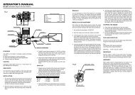


![Spartan Quark Gyro Installation Guide [Doc. v1.0] - Spartan RC](https://img.yumpu.com/53147979/1/190x196/spartan-quark-gyro-installation-guide-doc-v10-spartan-rc.jpg?quality=85)