![Spartan Quark Gyro Installation Guide [Doc. v1.0] - Spartan RC](https://img.yumpu.com/53147979/1/500x640/spartan-quark-gyro-installation-guide-doc-v10-spartan-rc.jpg)
Spartan Quark Gyro Installation Guide [Doc. v1.0] - Spartan RC
Spartan Quark Gyro Installation Guide [Doc. v1.0] - Spartan RC
Spartan Quark Gyro Installation Guide [Doc. v1.0] - Spartan RC
- No tags were found...

Create successful ePaper yourself
Turn your PDF publications into a flip-book with our unique Google optimized e-Paper software.
SPECIFICATION<br />
Radio compatibility: All PCM, PPM and 2.4GHz radios<br />
supporting the standard servo connector pinout (signal,<br />
power, ground).<br />
Servo compatibility: Digital servos as specified in this user<br />
guide.<br />
Servo pulse resolution: 250nSec<br />
Operating voltage: 3.8V – 8.4 Volts, current draw
WARNING!<br />
Model helicopters are not toys and have the potential to be<br />
very dangerous. Failure to follow the safety precautions and<br />
warnings in this user guide may result in severe injury to<br />
yourself and others. Beginners are advised to seek further<br />
advice from an experienced adult pilot.<br />
Read through the entire manual before operating this product.<br />
This product contains chemicals known to the State of<br />
California to cause cancer and birth defects or other<br />
reproductive harm.<br />
Safety Precautions<br />
BEFORE EACH FLIGHT:<br />
• Verify that the gyro operates correctly.<br />
• Verify that the gyro compensates in the correct direction.<br />
• Verify that the gyro is operating in the desired mode.<br />
• Verify that the gyro mounting pads are in good condition.<br />
• Verify that the gyro wires are not contacting the frame of<br />
the helicopter.<br />
• Verify that all tail linkages, ball links and tail hub bearings<br />
can move freely without excessive friction.<br />
2
OVERVIEW<br />
Measuring a mere 20.6mm square and 9.1mm tall (0.81 x<br />
0.81 x 0.36 inch) your new <strong>Spartan</strong> <strong>Quark</strong> TM gyro is the<br />
smallest and lightest heading hold gyro in its class. Its<br />
cutting-edge MEMS (Micro Electrical Mechanical System)<br />
sensor, powerful Digital Signal Controller and <strong>Spartan</strong>’s<br />
market leading adaptive tail control technology offer optimal<br />
gyro performance and exceptionally consistent yaw rates on<br />
any size helicopter from tiny electric to the largest nitro<br />
helicopters. The holding ability of the gyro is excellent and<br />
precise giving a very solid and dependable feel.<br />
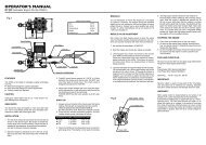
INTE<strong>RC</strong>ONNECTIONS<br />
(red plug)<br />
Connect to receiver’s<br />
gyro gain output. Also<br />
used for data link.<br />
(black plug)<br />
Connect to receiver’s<br />
rudder output.<br />
Connect to digital<br />
tail servo.<br />
3
STATUS LIGHT<br />
Operating Mode<br />
Error Codes<br />
Set<br />
up<br />
4<br />
Status Light<br />
Steady red<br />
Steady blue<br />
Blue 2 flashes<br />
Blue slow<br />
flashing<br />
Alternating<br />
blue/red<br />
Red slow<br />
flashing<br />
Red 1 flash<br />
Red 2 flashes<br />
Red 3 flashes<br />
Steady violet or<br />
flashing<br />
Description<br />
Rate mode.<br />
AVCS mode.<br />
AVCS mode - Rudder stick not<br />
centred.<br />
Start conditions not met. <strong>Gyro</strong> gain<br />
is set to less than 5%.<br />
<strong>Gyro</strong> calibrating.<br />
<strong>Gyro</strong> not receiving both rudder and<br />
gain signals. Possibly not produced<br />
by the receiver.<br />
<strong>Gyro</strong> not receiving rudder signal.<br />
Rudder plug is fitted incorrectly or<br />
broken yellow wire.<br />
<strong>Gyro</strong> not receiving gain signal.<br />
Gain plug is fitted incorrectly or<br />
broken orange wire.<br />
Power on calibration or self-test<br />
failed. Cycle power. If the problem<br />
persists contact technical support.<br />
See Servo Type Selection and <strong>Gyro</strong><br />
Configuration sections.
SETTING UP YOUR GYRO FOR THE FIRST TIME<br />
Follow the steps below in the specified order to successfully<br />
deploy your new <strong>Spartan</strong> gyro.<br />
Fix the gyro on your model following the instructions shown<br />
in the <strong>Gyro</strong> Mounting section later in this guide.<br />
Connect the gyro to the receiver as shown in the<br />
Interconnections section of this guide. Do not connect<br />
the servo to the gyro at this time.<br />
Ensure that the transmitter trims and sub-trims are set to<br />
zero and that collective pitch to tail pitch mixing is disabled.<br />
Select the correct servo type as described in the Servo<br />
Type Selection section of this guide.<br />
Connect the servo to the gyro.<br />
Follow the instruction in the Linkage Setup section of this<br />
guide to set the correct mechanical geometry of the tail.<br />
Adjust rudder direction reversing at your transmitter.<br />
Configure gyro reversing and servo endpoint as described<br />
in the <strong>Gyro</strong> Configuration chapter if this guide.<br />
Adjust gyro gain for both Rate and AVCS modes via your<br />
transmitter. See <strong>Gyro</strong> Gain and Mode section.<br />
Confirm tail rotor pitch changes in the correct direction to<br />
oppose any movement of the tail. Confirm the rudder stick<br />
produces the desired tail pitch movement and that there is<br />
no mechanical binding. See Tail Rotor Pitch section.<br />
5
GYRO MOUNTING<br />
The correct operation, performance and stability of your<br />
<strong>Spartan</strong> gyro can be greatly affected by the way it is fixed on<br />
the aircraft.<br />
WARNING!<br />
• It is essential that the gyro is mounted on a rigid flat<br />
surface accurately perpendicular to the main shaft.<br />
• Do not mount the gyro in locations where it may be<br />
subjected to high levels of oily smoke, fuel, or other liquids.<br />
• Do not allow the gyro case to touch other objects.<br />
• Do not allow the gyro cable to touch the sharp edge of the<br />
helicopter frames.<br />
• Avoid mounting the gyro in direct proximity to other<br />
electronic equipment and particularly servos.<br />
• Avoid fixing the cable to the helicopter for the first 5cm (2<br />
inches) from the gyro end to reduce transmission of vibrations<br />
through the cable.<br />
• Do not fit cable braid over the gyro wires.<br />
• Inspect the condition of the adhesive pads as part of your<br />
regular pre-flight checks.<br />
6
The supplied mounting kit contains a stainless steel plate and<br />
adhesive foam pads which have been selected by <strong>Spartan</strong> to<br />
give the correct mass and shore hardness for effective<br />
vibration damping. Always use the supplied mounting pads or<br />
the <strong>Spartan</strong> replacement mounting pads available from your<br />
<strong>Spartan</strong> gyro retailer.<br />
Small electric helicopters (250, 450 and 500 size) – Use<br />
a single 3mm foam pad without the steel plate.<br />
Larger electric and nitro helicopters – Use a piece of the<br />
1mm adhesive tape to mount the gyro on the steel plate and<br />
a 3mm foam pad to mount the plate to the helicopter.<br />
High vibration environments – Use a 3mm foam pad on<br />
each side of the supplied steel plate.<br />
SET button on rear<br />
side of gyro<br />
1mm tape or<br />
3mm foam pad<br />
Stainless steel plate<br />
3mm adhesive foam pad<br />
7
LINKAGE SETUP<br />
The optimal mechanical setup is essential for getting the best<br />
performance from your high end <strong>Spartan</strong> gyro. Ensure that<br />
any slop in the system is kept to a minimum and that the tail<br />
pitch linkages can move freely without excessive friction<br />
through any guides, ball links or other joints.<br />
With the gyro set to Rate mode and the rudder stick<br />
positioned at the centre the servo arm should be at a 90°<br />
angle with the pushrod as illustrated. To fly in Rate mode set<br />
the linkage lengths for approximately 8° tail pitch in the<br />
direction that compensates the main rotor torque.<br />
8<br />
90°<br />
Small Electric<br />
Helicopters<br />
(250, 450 and 500)<br />
Ball link 7.5mm<br />
from servo shaft<br />
Follow the advice in<br />
the helicopter’s<br />
assembly manual<br />
regarding the<br />
placement of the ball<br />
link onto the tail<br />
servo horn. When<br />
such advice is not<br />
provided or has<br />
resulted in poor tail<br />
performance we<br />
recommend placing
the ball link at<br />
7.5mm in the<br />
case of small<br />
electric<br />
helicopters and<br />
13.5 - 16.5mm<br />
for the larger<br />
electric and all<br />
nitro<br />
helicopters.<br />
Alternatively<br />
90°<br />
Larger Electric and<br />
All Nitro Helicopters<br />
13.5 - 16.5mm<br />
from servo shaft<br />
you may choose to place the ball link at a distance that allows<br />
the servo to have a combined travel of around 80° from the<br />
low endpoint to the high endpoint.<br />
SERVO TYPE SELECTION<br />
<strong>Spartan</strong> gyros are designed to work with all modern digital tail<br />
servos and offer a selection of servo pulse modulations in<br />
order to achieve such broad compatibility.<br />
To access the servo configuration mode hold the SET button<br />
pressed before powering on the gyro. Continue to hold the<br />
SET button pressed until the Status light starts flashings in<br />
9
violet colour. The number of flashes indicates the currently<br />
selected servo type.<br />
WARNING!<br />
The selected servo type must match the servo you are using.<br />
Incorrect setting may damage the servo and possibly<br />
resulting in a loss of tail control during flight.<br />
You must change the servo type before connecting the servo<br />
to the gyro. Disconnect the servo if already connected.<br />
Do not attempt to use analogue servos. Severe damage may<br />
be caused to your servo or loss of tail control during flight.<br />
Do not attempt to fly your model while the servo type<br />
selection mode is active, tail stabilisation will not function.<br />
To change the servo type move the rudder stick left or right<br />
until the desired option is reached. Press the SET button once<br />
to store your selection. The Status light turns on in steady<br />
violet colour to acknowledge that the servo type is changed.<br />
You may now power off the gyro.<br />
10
Light<br />
Servo modulation<br />
1520uSec at 333Hz<br />
Futaba S9253 / S9254 / S9257 / S9650 / S3153 /<br />
S3154, BLS254, JR 8900G / 3400G / 3500G, Align<br />
DS410 / DS420 / DS510 / DS520 / DS610 / DS620 /<br />
DS650, Sanwa ERG-WRX, Airtronics 94758 / 94761,<br />
Hitec 5925MG / 6965HB / 5083MG, Robbe FS61BB<br />
2 760uSec at 560Hz<br />
Futaba S9251 / S9256 / BLS251, MKS DS8910 /<br />
BLS980<br />
3 1520uSec at 250Hz<br />
JR 2700G / 8700G / 810G, Sky HDS-577 / HDS-877<br />
4 960uSec at 333Hz<br />
LogicTech 6100G / 3100G, Hitec 5083MG<br />
1 flash<br />
(default)<br />
Not listed servos - If your servo is not listed in the above<br />
table please visit the support knowledge on the <strong>Spartan</strong><br />
website and consult topic 12.<br />
GYRO CONFIGURATION<br />
To access the configuration mode power on the gyro and wait<br />
until it has finished calibrating. Press and hold the SET button<br />
for a few seconds. Once the configuration mode is active the<br />
tail servo chatters twice then rests in its centre position.<br />
11
WARNING!<br />
Do not attempt to fly your model while the gyro configuration<br />
mode is active, tail stabilisation will not function.<br />
Before configuring your gyro ensure that the rudder reversing<br />
has been correctly set at the transmitter. The gyro relies on<br />
this configuration to adjust its internal gyro direction<br />
reversing as required. Failure to follow this step correctly<br />
could result in violent pirouetting on take-off and loss of tail<br />
control. Before proceeding confirm the correct operation of<br />
the rudder stick by observing the tail rotor blades as<br />
explained in the Tail Rotor Pitch section of this guide.<br />
To prevent damage to the servo disconnect the tail control<br />
linkage from the servo before entering the gyro configuration<br />
mode. During adjustments simply hold the linkage over the<br />
linkage ball.<br />
Step 1: <strong>Gyro</strong> direction reversing<br />
The first parameter to be configured is gyro direction<br />
reversing. Simply push the rudder stick to the left and the<br />
gyro will automatically match your radio system. As the<br />
rudder stick is operated the tail blades move to allow visual<br />
confirmation of the correct rudder behaviour. The Status light<br />
switches on/off in violet to indicate if reversing is active.<br />
12
When satisfied, press the SET button briefly. The servo will<br />
chatter once to confirm completion of this step.<br />
Important: If the gyro is mounted in an inverted orientation<br />
you will need to push the rudder stick to the right instead.<br />
Step 2: Adjust low servo endpoint<br />
The servo is now resting at the low endpoint position and the<br />
Status light is flashing violet twice. Using the rudder stick<br />
adjust the servo position until you achieve maximum tail rotor<br />
pitch without binding on the mechanical limits. When<br />
satisfied, press the SET button briefly. The servo chatters<br />
once to confirm completion of this step.<br />
Important: Always set the gyro endpoints for the maximum<br />
available tail rotor pitch. This defines how much pitch the gyro<br />
can use and has no effect on how responsive the gyro feels in<br />
flight. If you find the yaw very responsive or very slow for<br />
your preference you may adjust this via the transmitter’s<br />
endpoints or Dual Rate setting for the rudder channel.<br />
Note: Whilst crossing the 100% endpoint value the servo<br />
pauses momentarily and the status light flashes blue.<br />
13
Step 3: Adjust high servo endpoint<br />
The servo is now resting at the high endpoint position and the<br />
Status light is flashing violet three times. Using the rudder<br />
stick adjust the servo position for maximum tail rotor pitch<br />
without binding. When satisfied, press the SET button briefly.<br />
The servo chatters twice to confirm completion of the<br />
configuration mode.<br />
Upon completion the gyro stores the new configuration to its<br />
internal memory and the Status light is steady violet. You<br />
may now power off the gyro.<br />
GYRO GAIN AND MODE<br />
<strong>Spartan</strong> gyros offer two operating modes, the classic Rate<br />
type and the AVCS (Angular Velocity Control System). To<br />
control the operating mode assign the gain channel to a two<br />
position switch of your transmitter. This switch now selects<br />
the operating mode whilst the gain channel endpoints control<br />
gyro gain for each mode. Your radio may also offer a<br />
dedicated gyro menu with more advanced configuration<br />
options for the gyro gain setting.<br />
The following table shows the relationship of the gyro<br />
operating gain in respect to the displayed value on the screen<br />
of some popular radio control transmitters.<br />
14
<strong>Gyro</strong> Operating Gain > 100%<br />
Rate<br />
80% 0% 77% 100%<br />
AVCS<br />
Gain Pulse Width 1020uS 1520uS 2020uS<br />
Futaba <strong>Gyro</strong> Menu 100% 0% 100%<br />
Futaba Endpoints 90% 0% 90%<br />
JR/Spektrum <strong>Gyro</strong> Menu - 0% 51% 100% -<br />
JR/Spektrum Endpoints 126% 1% 129%<br />
Important:<br />
• The optimal gain value is the highest value you can reach<br />
that does not cause tail wag at any time during flight.<br />
• Do not use any type of stick priority mixing or other gain<br />
reduction mixing.<br />
The optimal gain value is a function of several parameters<br />
including rotor speed, tail rotor diameter, tail blade efficiency,<br />
servo arm length, servo make/model and mechanical design<br />
of the aircraft. As such, it is not possible to make a general<br />
recommendation and therefore the gain will need to be<br />
adjusted experimentally. Start with a gain of 30%, this should<br />
provide enough stability to at least hover; however you<br />
should always proceed with care. If insufficient stabilisation or<br />
tail wag is seen the gain should be raised or lowered<br />
respectively. It is not uncommon to find that the optimal gain<br />
value for a helicopter could be as small as 35-45%. A small<br />
15
value does not mean that the gyro will be limited in<br />
performance. Any gain value performs well as long as it is the<br />
optimal gain value. However, a gain below 30% indicates that<br />
the mechanical gain of the tail is too high and therefore it is<br />
recommended to move the servo arm ball link further in.<br />
Similarly if 100% is reached and no tail wagging is seen the<br />
ball link needs to be moved further out.<br />
TAIL ROTOR PITCH<br />
Airframe<br />
manually<br />
rotated<br />
CW<br />
|<br />
OR<br />
|<br />
Airframe<br />
manually<br />
rotated<br />
CCW<br />
|<br />
OR<br />
|<br />
Left rudder<br />
input<br />
Right rudder<br />
input<br />
16<br />
Tail rotor<br />
thrust<br />
Tail blades as<br />
seen from above<br />
Tail rotor<br />
thrust<br />
Tail blades as<br />
seen from above
OPERATION<br />
It is advisable to power on the gyro in AVCS mode which<br />
enables it to recalibrate the rudder stick neutral. Stick neutral<br />
recalibration is not possible in Rate mode as any tail rotor<br />
mixing will interfere with the accuracy of this measurement.<br />
However should the gyro be accidentally powered on in Rate<br />
mode it will make use of the last known calibration value.<br />
WARNING!<br />
Immediately after powering on, the gyro performs automatic<br />
calibration of the rudder stick and gyro sensor resting<br />
positions. During this time the helicopter must remain<br />
undisturbed and the rudder stick must be left at the centre<br />
position. Calibration lasts approximately 4 seconds and upon<br />
completion the gyro will enter flight mode and the tail servo<br />
will move to its midpoint. During calibration the Status light<br />
colour alternates rapidly between red and blue.<br />
The calibration will not start if the gyro is not receiving the<br />
required rudder and gain signal from the receiver, or the start<br />
conditions are not met. In both cases the Status light will emit<br />
a flashing pattern to indicate the cause. These flashing<br />
patterns are listed in Status Light section of this guide.<br />
17
WARNING!<br />
If you plan on using the gyro in Rate mode you may need to<br />
program collective to tail rotor mixing on your transmitter.<br />
You must ensure that such mixing is active in Rate mode only.<br />
If the tail rotor mixing remains active in AVCS mode it can<br />
result in violent pirouetting and loss of tail control.<br />
If tail drift is seen in Rate mode it is advisable to trim the<br />
model mechanically by adjusting the linkage lengths. Small<br />
corrections can be done using the transmitter’s rudder trim,<br />
though this is not recommended. In the event that the<br />
transmitter’s trim is changed the gyro needs to recalibrate the<br />
rudder stick neutral. To do this, land and spool down the<br />
model, then rapidly toggle the gain switch three times<br />
(transitioning between Rate and AVCS modes) before<br />
returning it to the AVCS position. The rudder stick must be<br />
resting at the centre position while recalibration takes place.<br />
Important: If the radio’s rudder endpoints are set to a very<br />
high value, which results in a yaw demand above the sensing<br />
range of the gyro, the tail pitch will open fully producing ultrafast<br />
yaw rate of over 3 turns per second. While such fast yaw<br />
rates are spectacular you must ensure that your model is<br />
mechanically capable to withstand the increased loads.<br />
18
ADVANCED CONFIGURATION OPTIONS<br />
The gyro configuration can also be modified using the optional<br />
<strong>Spartan</strong> Fusion EDGE TM field programming unit, Flash-Link TM<br />
USB computer interface or Blue-Link TM radio module (see<br />
Spare Parts and Accessories section of this guide). Software is<br />
available on the <strong>Spartan</strong> website for Windows based<br />
computers and certain handheld devices. This configuration<br />
method provides access to a far greater number of operating<br />
parameters and thus more detailed customisation of your<br />
gyro’s flight performance and pilot’s feel.<br />
<strong>Spartan</strong> is committed to the continued improvement of their<br />
products and from time to time we produce new firmware<br />
versions offering optimisations and/or new functionality. The<br />
firmware of your gyro can be updated using the computer<br />
connectivity options mentioned above.<br />
COPYRIGHT AND LICENCE<br />
The documentation, electronic design and firmware are the<br />
Copyright of <strong>Spartan</strong> <strong>RC</strong>. The firmware is licensed for use only<br />
on products manufactured by <strong>Spartan</strong> <strong>RC</strong>. Reproduction and<br />
distribution of this document for non-commercial use is<br />
allowed. Reproduction must remain intact, as a complete<br />
whole, and including this notice.<br />
19
WARRANTY AND PRODUCT REGISTRATION<br />
This product is warranted to be free from defects in materials<br />
or workmanship for twelve months from the date of original<br />
purchase. Within this period, <strong>Spartan</strong> <strong>RC</strong> will, at its sole<br />
option, repair or replace any components which fail in normal<br />
use. Such repairs or replacement will be made at no charge to<br />
the customer for parts or labour, provided that the customer<br />
shall be responsible for any transportation costs. This<br />
warranty does not cover failures due to wear and tear, abuse,<br />
misuse, accident or unauthorized alterations or repairs. All<br />
warranty is return to base and the original dated sales receipt<br />
must be provided; we will not replace items in advance.<br />
<strong>Spartan</strong> <strong>RC</strong> retains the exclusive right to repair or replace the<br />
product or offer a full refund of the purchase price at its sole<br />
discretion. In no event shall <strong>Spartan</strong> <strong>RC</strong> be liable for any<br />
incidental, special, indirect or consequential damages<br />
resulting from the use, misuse or inability to use the product<br />
or from defects in the product.<br />
Important: Register your product via the <strong>Spartan</strong> website<br />
within 30 days of the original purchase to qualify for 3 years<br />
free service and discounted crash replacements. The original<br />
dated sales receipt is required for all claims. Terms and<br />
Conditions apply.<br />
20
SPARE PARTS AND ACCESSORIES<br />
Order Code Description<br />
S<strong>RC</strong>-QPADS Adhesive foam pad set.<br />
S<strong>RC</strong>-QVKIT Vibration attenuation kit. Includes pads and<br />
metal plate.<br />
S<strong>RC</strong>-FSN Fusion EDGE TM field programming unit and<br />
multifunction tester.<br />
S<strong>RC</strong>-FL Flash-Link TM (USB computer interface) *<br />
S<strong>RC</strong>-BL Blue-Link TM (Bluetooth radio module) *<br />
S<strong>RC</strong>-SLX * Also required: Simplex Data Adapter.<br />
S<strong>RC</strong>-QCMG Metal CNC gyro case. Dark Gold colour.<br />
S<strong>RC</strong>-QCLR Clear plastic gyro case.<br />
S<strong>RC</strong>-QPBK Black plastic gyro case.<br />
LIABILITY DISCLAIMER<br />
Because <strong>Spartan</strong> <strong>RC</strong> and their distributors have no control<br />
over the installation and use of this product, no liability may<br />
be assumed nor will any liability be accepted for any damages<br />
resulting from the use of this product. Under no<br />
circumstances will the buyer be entitled to consequential or<br />
incidental damages. By the act of installing this product, the<br />
buyer accepts all resulting liability.<br />
21