
Create successful ePaper yourself
Turn your PDF publications into a flip-book with our unique Google optimized e-Paper software.
Safety InformationPlease read this owner’s guidePlease take the time to follow the instructions in this owner’s guide carefully. It will help you set up and operateyour system properly and enjoy all of its advanced features. Please save this owner’s guide for future reference.WARNING: To reduce the risk of fire or electrical shock, do not expose the product to rain or moisture.WARNING: The apparatus shall not be exposed to dripping or splashing, and objects filled with liquids, such as vases,shall not be placed on the apparatus. As with any electronic products, use care not to spill liquids into any part of thesystem. Liquids can cause a failure and/or a fire hazard.The lightning flash with arrowhead symbol within an equilateral triangle alerts the user to the presence ofuninsulated, dangerous voltage within the system enclosure that may be of sufficient magnitude toconstitute a risk of electrical shock.The exclamation point within an equilateral triangle, as marked on the system, is intended to alert theuser to the presence of important operating and maintenance instructions in this owner’s guide.CAUTION: Make no modification to the system or accessories. Unauthorized alterations may compromise safety,regulatory compliance, and system performance.CAUTION: This product shall be connected to a mains socket outlet with a protective earthing connection.This product conforms to the EMC Directive 89/336/EEC and to the Low VoltageDirective 73/23/EEC. The complete Declaration of Conformity can be found onwww.Bose.com/static/compliance/index.html.Note: Where the mains plug or appliance coupler is used as the disconnect device, such disconnect device shallremain readily operable.Note: The product must be used indoors. It is neither designed nor tested for use outdoors, in recreation vehicles, oron boats.Note: Provide an earth connection before the main plug is connected to the mains.ii
Important Safety InformationCaution marks on the productThese CAUTION marks are located on the back of the product.The lightning flash with arrowhead symbol, within an equilateraltriangle, is intended to alert the user to the presence of uninsulateddangerous voltage within the system enclosure that maybe of sufficient magnitude to constitute a risk of electric shock.The exclamation point within an equilateral triangle, as markedon the system, is intended to alert the user to the presence ofimportant operating and maintenance instructions in thisowner’s guide.Important safety instructions1. Read these instructions.2. Keep these instructions3. Heed all warnings.4. Follow all instructions.5. Do not use this apparatus near water.6. Clean only with a dry cloth.7. Do not block any ventilation openings. Install in accordancewith the manufacturer’s instructions – To ensure reliable operationof the product and to protect it from overheating, put the productin a position and location that will not interfere with its properventilation.8. Do not install near any heat sources, such as radiators, heatregisters, stoves, or other apparatus (including amplifiers) thatproduce heat.9. Do not defeat the safety purpose of the polarized or groundingtypeplug. A polarized plug has two blades with one wider thanthe other. A grounding-type plug has two blades and a thirdgrounding prong. The wider blade or third prong are providedfor your safety. If the provided plug does not fit into your outlet,consult an electrician for replacement of the obsolete outlet.10. Protect the power cord from being walked on or pinched, particularlyat plugs, convenience receptacles, and the point wherethey exit from the apparatus.11. Only use attachments/accessories specified by themanufacturer.12. Use only with the cart, stand, tripod, bracket, ortable specified by the manufacturer or sold with theapparatus. When a cart is used, use caution whenmoving the cart/apparatus combination to avoidinjury from tip-over.13. Unplug this apparatus during lightning storms or when unusedfor long periods of time.14. Refer all servicing to qualified service personnel. Servicing isrequired when the apparatus has been damaged in any waysuch as power-supply cord or plug is damaged; liquid has beenspilled or objects have fallen into the apparatus; the apparatushas been exposed to rain or moisture, does not operate normally,or has been dropped.15. To prevent risk of fire or electric shock, avoid overloading walloutlets, extension cords, or integral convenience receptacles.16. Do not let objects or liquids enter the product – as they maytouch dangerous voltage points or short-out parts that could resultin a fire or electric shock.17. See product enclosure for safety related markings.18. No naked flame sources, such as lighted candles, should beplaced on the apparatus.WARNING: To reduce the risk of fire or electric shock, do notexpose the amplifier to rain or moisture.Information about products thatgenerate electrical noiseIf applicable, this equipment has been tested and found to complywith the limits for a Class A digital device, pursuant to Part 15of the FCC rules. These limits are designed to provide reasonableprotection against harmful interference in a residential installation.This equipment generates, uses, and can radiate radio frequencyenergy and, if not installed and used in accordance withthe instructions, may cause harmful interference to radio communications.However, this is no guarantee that interference will notoccur in a particular installation. If this equipment does causeharmful interference to radio or television reception, which can bedetermined by turning the equipment off and on, you are encouragedto try to correct the interference by one or more of the followingmeasures:• Reorient or relocate the receiving antenna.• Increase the separation between the equipment and receiver.• Connect the equipment to an outlet on a different circuit thanthe one to which the receiver is connected.• Consult the dealer or an experienced radio/TV technician forhelp.Note: Unauthorized modification of the receiver or radio remotecontrol could void the user’s authority to operate this equipment.This product complies with the Canadian ICES-003 Class Bspecifications.The information furnished in this user’s guide does not include allof the details of design, production, or variations of the equipment.Nor does it cover every possible situation which may ariseduring installation, operation, or maintenance. If you need assistancebeyond the scope of this user’s guide, please contact ourCustomer Service department. See “Customer support” onpage 60.iii
Contents1.0 <strong>FreeSpace</strong> ® <strong>4400</strong> Introduction . . . . . . . . . . . . . . . . . . . 21.1 The Bose ® <strong>FreeSpace</strong> ® <strong>4400</strong><strong>Business</strong> <strong>Music</strong> <strong>System</strong> . . . . . . . . . . . . . . . . . . 21.2 <strong>FreeSpace</strong> <strong>4400</strong> system accessories . . . . . . . . . . 21.3 <strong>FreeSpace</strong> <strong>4400</strong> Installersoftware . . . . . . . . . . . . . . . . . . . . . . . . . . . . . . . 32.0 Designing with the <strong>FreeSpace</strong> ® <strong>4400</strong> <strong>System</strong> . . . . . . . 42.1 Introduction . . . . . . . . . . . . . . . . . . . . . . . . . . . . . . 42.2 Basic design steps . . . . . . . . . . . . . . . . . . . . . . . . . 42.2.1 Step 1 – Determine source routing . . . . . . . . 42.2.2 Step 2 – Determine Auto Volumerequirements . . . . . . . . . . . . . . . . . . . . . . 42.2.3 Step 3 – Determine volume controlrequirements . . . . . . . . . . . . . . . . . . . . . . 72.2.4 Step 4 – Determine the loudspeakerrequirements . . . . . . . . . . . . . . . . . . . . . . 72.2.5 Step 5 – Determine the <strong>FreeSpace</strong> ® <strong>4400</strong>requirements . . . . . . . . . . . . . . . . . . . . . . 82.3 Auto Volume layout examples . . . . . . . . . . . . . . . . 93.0 <strong>FreeSpace</strong> ® <strong>4400</strong> Hardware Description . . . . . . . . . . . 123.1 Front panel . . . . . . . . . . . . . . . . . . . . . . . . . . . . . . . 123.1.1 Controls . . . . . . . . . . . . . . . . . . . . . . . . . . . . . 123.1.2 Indicators . . . . . . . . . . . . . . . . . . . . . . . . . . . 123.2 Rear panel . . . . . . . . . . . . . . . . . . . . . . . . . . . . . . . 133.2.1 <strong>System</strong> controls . . . . . . . . . . . . . . . . . . . . . . 133.2.2 Audio source inputs . . . . . . . . . . . . . . . . . . . 133.2.3 Amplifier outputs . . . . . . . . . . . . . . . . . . . . . . 133.2.4 AC power . . . . . . . . . . . . . . . . . . . . . . . . . . . 134.0 Hardware Installation . . . . . . . . . . . . . . . . . . . . . . . . . . 144.1 Introduction . . . . . . . . . . . . . . . . . . . . . . . . . . . . . . 144.2 Included accessories . . . . . . . . . . . . . . . . . . . . . . . 144.3 Placement guidelines . . . . . . . . . . . . . . . . . . . . . . . 144.4 Shelf mounting the <strong>FreeSpace</strong> <strong>4400</strong> system . . . . . 144.5 Rack mounting the <strong>FreeSpace</strong> <strong>4400</strong> system . . . . . 154.6 Installing accessories . . . . . . . . . . . . . . . . . . . . . . . 164.6.1 Sensing microphones . . . . . . . . . . . . . . . . . . 164.6.2 Auto volume microphone inputs . . . . . . . . . . 164.6.3 User interfaces . . . . . . . . . . . . . . . . . . . . . . . 164.6.4 User interface connections . . . . . . . . . . . . . . 184.7 <strong>System</strong> wiring . . . . . . . . . . . . . . . . . . . . . . . . . . . . . 194.7.1 Serial data communications . . . . . . . . . . . . . 194.7.2 Remote standby switch . . . . . . . . . . . . . . . . 194.7.3 LINE 1/LINE 2 source input . . . . . . . . . . . . . . 204.7.4 AUX MIC/LINE 3 source input . . . . . . . . . . . . 204.7.5 PAGE/MIC/LINE 4 source input . . . . . . . . . . 214.7.6 DIRECT IN/CONTROL source input . . . . . . . 214.7.7 Amplifier ZONE OUTPUT outputs . . . . . . . . . 224.7.8 Output voltage setting (70/100V) . . . . . . . . . 224.7.9 ZONE 4 LINE OUT output . . . . . . . . . . . . . . . 234.8 AC power connections . . . . . . . . . . . . . . . . . . . . . . 234.8.1 Fuse type . . . . . . . . . . . . . . . . . . . . . . . . . . . . 234.8.2 AC POWER connection . . . . . . . . . . . . . . . . 235.0 Using <strong>FreeSpace</strong> ® <strong>4400</strong> Installer Software . . . . . . . . 245.1 Installing the software . . . . . . . . . . . . . . . . . . . . . . 245.2 Connecting to the <strong>FreeSpace</strong> <strong>4400</strong> system . . . . . . 245.2.1 No hardware detected . . . . . . . . . . . . . . . . . 265.2.2 Incompatible microcontroller code . . . . . . . . 265.2.3 Sample design files . . . . . . . . . . . . . . . . . . . . 265.3 The <strong>FreeSpace</strong> <strong>4400</strong> Installer softwareuser interface . . . . . . . . . . . . . . . . . . . . . . . . . . . 275.4 Set Up Hardware mode . . . . . . . . . . . . . . . . . . . . . 295.5 Set Up Schedule mode . . . . . . . . . . . . . . . . . . . . . 305.5.1 Setting the clock . . . . . . . . . . . . . . . . . . . . . . 315.5.2 Adding events . . . . . . . . . . . . . . . . . . . . . . . . 315.5.3 Viewing and changing event settings . . . . . . 325.5.4 Removing events from the list . . . . . . . . . . . . 325.6 Service Hardware mode . . . . . . . . . . . . . . . . . . . . . 336.0 <strong>FreeSpace</strong> ® <strong>4400</strong> <strong>System</strong> Setup . . . . . . . . . . . . . . . . . . 346.1 Introduction . . . . . . . . . . . . . . . . . . . . . . . . . . . . . . 346.2 Connecting your PC to a <strong>FreeSpace</strong> <strong>4400</strong> system 346.3 <strong>System</strong> setup procedure . . . . . . . . . . . . . . . . . . . . 356.3.1 Output gain . . . . . . . . . . . . . . . . . . . . . . . . . . 356.3.2 Zone setup . . . . . . . . . . . . . . . . . . . . . . . . . . 366.3.3 Input gain . . . . . . . . . . . . . . . . . . . . . . . . . . . . 376.3.4 Source assign . . . . . . . . . . . . . . . . . . . . . . . . 396.3.5 Source EQ . . . . . . . . . . . . . . . . . . . . . . . . . . . 406.3.6 Page setup . . . . . . . . . . . . . . . . . . . . . . . . . . 406.3.7 Zone EQ . . . . . . . . . . . . . . . . . . . . . . . . . . . . 426.3.8 Dynamic EQ . . . . . . . . . . . . . . . . . . . . . . . . . . 436.3.9 Auto Volume . . . . . . . . . . . . . . . . . . . . . . . . . 437.0 User Interface Operation . . . . . . . . . . . . . . . . . . . . . . . . 497.1 Enabling keypad operation . . . . . . . . . . . . . . . . . . . 497.2 Turning the system on . . . . . . . . . . . . . . . . . . . . . . 497.3 AVM user interface operation . . . . . . . . . . . . . . . . . 497.4 Page user interface operation . . . . . . . . . . . . . . . . 518.0 <strong>FreeSpace</strong> ® <strong>4400</strong> <strong>System</strong> Troubleshooting . . . . . . . . . 528.1 Introduction . . . . . . . . . . . . . . . . . . . . . . . . . . . . . . 528.2 <strong>FreeSpace</strong> <strong>4400</strong> hardwareindicators . . . . . . . . . . . . . . . . . . . . . . . . . . . . . . 528.2.1 Normal operation . . . . . . . . . . . . . . . . . . . . . . 528.2.2 <strong>System</strong> fault . . . . . . . . . . . . . . . . . . . . . . . . . . 528.2.3 Amplifier fault . . . . . . . . . . . . . . . . . . . . . . . . . 538.2.4 Input clipping . . . . . . . . . . . . . . . . . . . . . . . . . 548.2.5 Direct input is active . . . . . . . . . . . . . . . . . . . 548.2.6 No STANDBY and SYSTEM indicators . . . . . 548.3 <strong>FreeSpace</strong> ® <strong>4400</strong> system Error Log . . . . . . . . . . . . 558.3.1 Contents of the Error Log . . . . . . . . . . . . . . . 558.3.2 Hardware configuration . . . . . . . . . . . . . . . . . 558.3.3 Power-on self-test results . . . . . . . . . . . . . . . 558.3.4 Amplifier alarms . . . . . . . . . . . . . . . . . . . . . . . 568.3.5 Solving faults reported in the Error Log . . . . 578.4 Common problems . . . . . . . . . . . . . . . . . . . . . . . . . 588.4.1 Communications port error . . . . . . . . . . . . . . 588.4.2 No audio in zone . . . . . . . . . . . . . . . . . . . . . . 588.4.3 User interface keypads do notoperate correctly . . . . . . . . . . . . . . . . . . . 598.4.4 Bad sound in a zone . . . . . . . . . . . . . . . . . . . 598.4.5 Auto Volume does not calibrate . . . . . . . . . . 608.5 Customer support . . . . . . . . . . . . . . . . . . . . . . . . . 608.5.1 Technical assistance . . . . . . . . . . . . . . . . . . . 608.5.2 Reporting software bugs and issues . . . . . . . 609.0 Restoring <strong>FreeSpace</strong> ® <strong>4400</strong> Microcontroller Code . . . . 6210.0 Technical Specifications . . . . . . . . . . . . . . . . . . . . . . . 6410.1 Power amplifier . . . . . . . . . . . . . . . . . . . . . . . . . . . 6410.2 Digital signal processing . . . . . . . . . . . . . . . . . . . 6410.3 Front panel indicators and control connections . . 6410.4 Rear panel inputs, outputs, and controls . . . . . . . 6410.5 <strong>FreeSpace</strong> <strong>4400</strong> system serial data commands . 64III
1.3 <strong>FreeSpace</strong> <strong>4400</strong> Installersoftware1.0 <strong>FreeSpace</strong> ® <strong>4400</strong> Introduction<strong>FreeSpace</strong> ® <strong>4400</strong> Installer software is included with every<strong>FreeSpace</strong> <strong>4400</strong> system. The <strong>FreeSpace</strong> <strong>4400</strong> Installer softwareallows you to configure hardware devices such as the <strong>FreeSpace</strong><strong>4400</strong> system. The <strong>FreeSpace</strong> <strong>4400</strong> Installer software is designedfor use on a PC that is connected to the <strong>FreeSpace</strong> <strong>4400</strong> systemthrough a serial data interface.The <strong>FreeSpace</strong> <strong>4400</strong> Installer software requires a computer systemwith the following minimum requirements:• 400 MHz Pentium ® -based PC• 256 MB of RAM• 60 MB of available hard-drive space• RS-232 serial port• 800 x 600 display• 4x CD-ROM drive• Microsoft Windows ® 98, Windows ® 98SE, Windows ® NT,Windows ® 2000, Windows ® XP3 of 66
2.0 Designing with the <strong>FreeSpace</strong> ® <strong>4400</strong> <strong>System</strong>2.1 IntroductionThis section describes the basic steps for designing a <strong>FreeSpace</strong><strong>4400</strong> system and includes an example. It is assumed that a completeloudspeaker design and layout has already been created.2.2 Basic design stepsThere are five basic steps in designing a <strong>FreeSpace</strong> <strong>4400</strong> system.2.2.1 Step 1 – Determine source routingDecide which sources will be played in each area. Create a“source map” such as the following one that shows whichsources will be played in each major area of the facility.Source 1 Source 2 Source 3 Source 4Area 1 ● ●Area 2 ● ● ●Area 3 ● ●Area 4Area 5●●2.2.2 Step 2 – Determine Auto VolumerequirementsIdentify which areas will use Auto Volume. Each Auto Volumezone must use one AVM (Auto Volume) user interface and oneBose ® sensing microphone to control the volume.When using Auto Volume, remember that you will be adjustingthe volume of an overall area. Imagine that you have a dining areaand a bar adjacent to one another. If the sensing microphone isplaced above the bar, the music may become too loud in the diningarea. Likewise, if you place the sensing microphone abovethe dining area, the music may never be heard in the bar.Guidelines for establishing Auto Volume zonesLoudspeakerheight is…Background noiseis uniform>25 ft (7.6 m) Not recommended12-25 ft(3.7-7.6 m)One Auto Volumezone for every3600 ft 2 (324 m 2 )
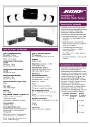
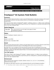
2.0 Designing with the <strong>FreeSpace</strong> ® <strong>4400</strong> <strong>System</strong>The following are examples of correct and incorrect sensingmicrophone placements:Correct placementSensingmicrophoneCeiling FlushIncorrect placementSensingmicrophoneCorrect placementSensingmicrophoneWall SurfaceIncorrect placementSensingmicrophoneMicInstaller’s Note: In applications where ceiling height is lessthan 12 ft (3.6 m), the microphone should be wall mounted.5 of 66
2.0 Designing with the <strong>FreeSpace</strong> ® <strong>4400</strong> <strong>System</strong>2.2.3 Step 3 – Determine volumecontrol requirementsDecide which areas will have volume controls. Create a controlmap, such as the following, showing the types of controls thatwill be used, and the areas in which they will be installed.Area 1Area 2Area 3Area 4AVM (AutoVolume)Interface1●AVM (AutoVolume)Interface2●AVM(Mute)Interface1AVM(Mute)Interface2When determining the placement or physical location of the controls,first think about how the control is used. If the control isvery rarely used or it requires a secure location, it should beplaced with the equipment. If the control is for an area thatrequires frequent adjustments, then it is best to place the controlin the area being controlled.●●2.2.4 Step 4 – Determine the loudspeakerrequirementsDetermine the loudspeaker coverage required for the design.Consider the following points as you do this:• Each Auto Volume function requires a separate zone. EachAuto Volume zone requires the dedicated use of one<strong>FreeSpace</strong> <strong>4400</strong> output channel.• Each type of specifically equalized Bose loudspeaker requiresthe dedicated use of one <strong>FreeSpace</strong> <strong>4400</strong> output channel. Ifyou are designing a system that uses specific Bose loudspeakerequalization, such as the 102 ® F loudspeaker, Model32, Model 32SE, or Model 8, you must dedicate one<strong>FreeSpace</strong> <strong>4400</strong> output channel for each loudspeaker type.Create a loudspeaker map, such as the following, and match theloudspeaker models to areas (Loudspeaker Qty x Tap = ZonePower required):Area 5 ● Model <strong>FreeSpace</strong>LoudspeakerArea32SE 3-I Qty Tap PowerAVM (Auto Volume/Mute) user interfaces are available for usewith the <strong>FreeSpace</strong> ® <strong>4400</strong> system. They offers control oversource selection and volume. The interface can be configured asArea 1 ● 2 50 100an AVM (Mute) interface or as an AVM (Auto Volume) interface. Ifyou have identified an area that uses auto volume, you must configureArea 2 ● 5 8 40the interface as an AVM (Auto Volume) interface to controlthis zone.Area 3 ● 1 50 50It is also possible to use a 70/100V in-line volume controlbetween the amplifier output and the loudspeaker. If you plan touse a 70/100V in-line volume control, be aware that they cannotbe used in zones where either Auto Volume or Dynamic EQ isused. Auto Volume and Dynamic EQ monitor the amplifier outputand make adjustments accordingly. Using an in-line volume controlwould cause these functions to operate improperly.Area 4Area 5●●364812487 of 66
2.0 Designing with the <strong>FreeSpace</strong> ® <strong>4400</strong> <strong>System</strong>2.2.5 Step 5 – Determine the<strong>FreeSpace</strong> ® <strong>4400</strong> requirementsOnce you have identified the areas that use Auto Volume andspecifically equalized Bose loudspeakers, you can combine differentareas based on the types of sources and controls they areusing.Now we can take a look at how the maps we created can help usdetermine the quantity of <strong>FreeSpace</strong> <strong>4400</strong>s we will need.Sources Controls Loudspeakers1 2 3 4 AV1 AV2 VC1 VC2 M32SE FS3 Total W<strong>4400</strong>Ch.Area 1 ● ● ● ● 100 1Area 2 ● ● ● ● ● 40 2Area 3 ● ● ● ● 50 3Area 4 ● ● ● 12 4Area 5 ● ● ● 48 4Total <strong>System</strong> Power = 250WBy combining the maps you can easily combine sources, loudspeaker types, and control types. The informationplaced in this table suggests that Area 1 and Area 3 need to be grouped separately because they are Auto Volumezones requiring separate <strong>FreeSpace</strong> <strong>4400</strong> system outputs. Area 2 uses one AVM (Mute) interface requiring one<strong>FreeSpace</strong> <strong>4400</strong> output channel. Areas 4 and 5 share a common volume control and can be combined on a third<strong>FreeSpace</strong> <strong>4400</strong> output channel. Since only four outputs are required and the total combined power requirement isless than 400W, only one <strong>FreeSpace</strong> <strong>4400</strong> unit would be needed for this system.8 of 66
2.0 Designing with the <strong>FreeSpace</strong> ® <strong>4400</strong> <strong>System</strong>2.3 Auto Volume layout examplesLarge, open retail space with single musicsource<strong>FreeSpace</strong> ® Acoustimass moduleModel 16 (pendant mounted)Sensing microphone9 of 66
2.0 Designing with the <strong>FreeSpace</strong> ® <strong>4400</strong> <strong>System</strong>Hair salon (Small space with specific noise)<strong>FreeSpace</strong> ® 3 systemSensing microphone10 of 66
2.0 Designing with the <strong>FreeSpace</strong> ® <strong>4400</strong> <strong>System</strong>Hotel lobby22 ft(6.7 m)40 ft(12.2 m)Model 16(flush mounted)Sensing microphone11 of 66
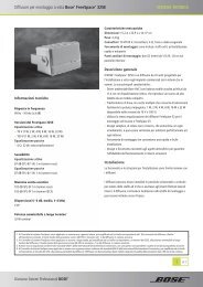
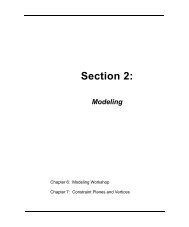
3.0 <strong>FreeSpace</strong> ® <strong>4400</strong> Hardware Description3.1 Front panel324 513.1.1 Controls1 STANDBY – The STANDBY button switches the unitbetween standby and active. The color of the LED above theswitch indicates the status:Amber = Unit is in standbyUnlit = Unit is active3.1.2 Indicators2 SYSTEM STATUS – The SYSTEM STATUS LED indicates thecondition of the unit:Green = Normal operationRed = Fault condition3 AMP OUTPUTS – These LEDs work in pairs (1 and 2, 3 and4) and indicate the operating status of the four amplifier outputchannels:Green = Normal operationRed = Fault conditionUnlit = No signal4 AUDIO SOURCES – These LEDs indicate the operatingstatus of the four input sources:Green = Good signalAmber = Low signalRed = Signal clippingUnlit = No signal5 DIRECT INPUT – The color of this LED indicates the conditionof the source connected to the DIRECT IN/CONTROL connectoron the rear panel.Amber = Active bypassUnlit = Normal operation12 of 66
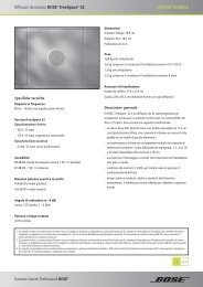
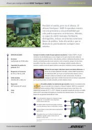
3.0 Freespace ® <strong>4400</strong> Hardware Description3.2 Rear panel126103478911513123.2.1 <strong>System</strong> controls3.2.3 Amplifier outputs1 SENSE MICROPHONES – Input connectors for sensingmicrophones used with the Auto Volume feature.2 RS-232 – Standard RS-232 communications port. Providesa communications interface for a PC running <strong>FreeSpace</strong> ® <strong>4400</strong>Installer software. The <strong>FreeSpace</strong> <strong>4400</strong> Installer software isused to configure the <strong>FreeSpace</strong> <strong>4400</strong> system.Note: The RS-232 port should only be used to connect a<strong>FreeSpace</strong> <strong>4400</strong> system to a PC.3 WALL PLATE CONNECTIONS – Input connectors for AVM1-Zone, AVM 2-Zone User Interface, or Page user interfaces.4 REMOTE ON/OFF – An input connector for a remoteSTANDBY switch.3.2.2 Audio source inputs5LINE 1/LINE 2 – Unbalanced audio inputsAUX MIC/LINE 3 – Balanced audio input with phantom powerPAGE/MIC/LINE 4 – Balanced audio input with phantom powerDIRECT IN/CONTROL – Balanced (DSP bypassed, full amplifiergain) audio input which can override the sources playing on allfour output channels6 ZONE OUTPUTS 1/2/3/4 – Loudspeaker connections forfour zonesInstaller’s Note: Please notice the polarity markings whenwiring loudspeaker cables to the ZONE OUTPUT connectors.CAUTION: DO NOT ground the minus (–) terminals.7 ZONE 4 LINE OUT – A line-level output that duplicates theprogram material from LINE 4. May be used to feed anotheramplifier installed for a large zone. The 12V control output is usedto connect to Bose ® amplifier sequence inputs.8 MUSIC ON HOLD/PBX OUT – An audio output used toprovide music input to a PBX system3.2.4 AC power9 OUTPUT VOLTAGE – Sets the ZONE OUTPUT lines to 70/100V.1011POWER ON/OFF – Switches AC power on or offFuse –T6.3(6,3)A L 250V (100/120V) orT3.15(3,15)A L 250V (220-240V).12AC MAINS LINE CORD JACK – AC line voltage input13 INPUT VOLTAGE – switches need to be configured forproper input voltage.13 of 66
4.0 Hardware Installation4.1 IntroductionThis section provides instructions for installing the <strong>FreeSpace</strong> ®<strong>4400</strong> system hardware on a tabletop or in a rack.4.2 Included accessoriesThe following accessories are shipped with the <strong>FreeSpace</strong> <strong>4400</strong>system.• 2-terminal input connectors (7) – For wiringAuto Volume mics to theSENSE MICROPHONES jacks• 3-terminal input connectors (2) – For wiringequipment to the AUX MIC/LINE 3 jacks• 4-terminal input connectors (4) – For wiringequipment to the ZONE 4 LINE OUT,PAGE/MIC/LINE 4, andDIRECT IN/CONTROL jacks• 2-terminal output connectors (5) – For wiringloudspeaker cables to the ZONE OUT-PUT jacks• Rubber feet (4) – For installing the<strong>FreeSpace</strong> <strong>4400</strong> system on a level surface4.3 Placement guidelines• Place the <strong>FreeSpace</strong> <strong>4400</strong> system where it is protected fromheat and allowed adequate ventilation.• Place the <strong>FreeSpace</strong> <strong>4400</strong> system away from direct heatsources, such as heating vents and radiators.• Make sure that air can circulate freely behind, beside, andabove the chassis for adequate ventilation. There are intakevents on the sides and an exhaust vent on the back of the unit.Do not cover or block the vents.Installer’s Note: Do not allow the chassis to exceed themaximum operating temperature of 50° C (122° F). Be awareof conditions in an enclosed rack that may increase the temperatureabove room-ambient conditions.4.4 Shelf mounting the <strong>FreeSpace</strong><strong>4400</strong> systemThe <strong>FreeSpace</strong> <strong>4400</strong> system is ideal for shelf mounting. Theincluded accessory kit contains four rubber feet for the bottom ofthe <strong>FreeSpace</strong> <strong>4400</strong> chassis. The rubber feet will protect the surfaceon which the <strong>FreeSpace</strong> <strong>4400</strong> system is installed and helpprevent movement of the <strong>FreeSpace</strong> <strong>4400</strong> system. Be sure to followthe “Placement Guidelines” previously described whenchoosing a location for the <strong>FreeSpace</strong> <strong>4400</strong> system.• Rack ears (2) ) – for rackmounting the the unit.Includes (8) M4 x 12mmscrews.• Replacement voltage label (2) – Used onthe OUTPUT VOLTAGE selection switch• <strong>FreeSpace</strong> <strong>4400</strong> Installer softwareCD – Contains application software forprogramming the <strong>FreeSpace</strong> <strong>4400</strong>system14 of 66
4.0 Hardware Installation4.5 Rack mounting the <strong>FreeSpace</strong><strong>4400</strong> systemThe <strong>FreeSpace</strong> <strong>4400</strong> system requires three 1.75" (44 mm) rackspace units with a 16" (406 mm) inside depth (including the rearsupports). When mounting, use four screws with washers to preventmarring the front panel. Neoprene rubber washers are agood choice because they grip the screw head and prevent thescrews from backing out from vibration or during transportation.Installer’s Note: If the <strong>FreeSpace</strong> <strong>4400</strong> system is to betransported while mounted in a rack, be advised that the rearof the <strong>FreeSpace</strong> <strong>4400</strong> system must be mechanically supported.Install a shelf under the unit or use brackets in such away as to support the rear of the unit. Failure to use propermounting hardware may result in damage to the <strong>FreeSpace</strong><strong>4400</strong> system during transport.Attaching rack ears to the <strong>FreeSpace</strong> <strong>4400</strong> chassisicAttaching the <strong>FreeSpace</strong> <strong>4400</strong> chassis to therack (mounting screws not provided)15 of 66
4.0 Hardware Installation4.6 Installing accessoriesInstaller’s Note: Disconnect the <strong>FreeSpace</strong> <strong>4400</strong> systemfrom the AC (mains) power before making any input/outputconnections.4.6.2 Auto volume microphone inputsConnect each sensing microphone to the SENSE MICRO-PHONES jacks on the <strong>FreeSpace</strong> <strong>4400</strong> rear panel.4.6.1 Sensing microphonesRequired accessory:<strong>FreeSpace</strong> ® <strong>4400</strong> <strong>System</strong> Auto Volume Mic Kit [PC042354 (U.S.),PC042355 (Euro)]Wall plate-microphoneassemblyPaint plug(2) Wire nutsMicrophone installation:The wall plate-microphone assembly can be installed using asingle-gang junction box, or the microphone can be removedfrom the wall plate and mounted directly on a flat surface.Junction box installation(2) #6-32 (3 mm) screwsSurface-mounted mic4.6.3 User interfacesRequired accessory: <strong>FreeSpace</strong> ® <strong>4400</strong> <strong>System</strong> AVM 1-ZoneUser Interface [PC042351] or<strong>FreeSpace</strong> ® <strong>4400</strong> <strong>System</strong> AVM 2-ZoneUser Interface [PC042352] or<strong>FreeSpace</strong> ® <strong>4400</strong> <strong>System</strong> Page UserInterface [PC042353]AWall plateBKeypadMUTE /AUTO VOLRecommended wire length:Up to 2000 ft (610 m) max., 24 AWG (0.2 mm 2 ) shielded twistedpair (shield tied to minus at <strong>FreeSpace</strong> <strong>4400</strong>, floated at sensemic).Painting:Before painting the wallplate, install the suppliedtemporary plugover the microphoneopening. Remove theplug when finished.Required additional equipment (not supplied):CRJ45connector*DCat 5 cable*(with 4 twisted pairs)EDouble-gangjunction boxMounting locations:For mounting instructions, see “Mounting guidelines for sensingmicrophones” on page 4.*<strong>FreeSpace</strong> ® <strong>4400</strong> <strong>System</strong> AVM 2-Zone User Interface requiresthe use of two (2) RJ45 connectors and two (2) Cat 5 cables.16 of 66
4.0 Hardware InstallationAssembly:EUser interface schematic -Page user interface:1 2 3 4 5 6 7 8+5VDABMUTE /AUTO VOLDLED+5VDD1R1562.33µF+5VDC7LEDD6R6562S1 Zone 1S6Zone 2User interface schematic -AVM (Auto Volume/Mute)user interface*:LED+5VDD1R1562S1 Source 1+5VD.33µF+5VDC71 2 3 4 5 6 7 8LEDS6+5VD+5VDD6R6562Volume UpLEDLEDS2+5VD+5VDD2R2562D3R3562Zone 3LEDLEDS5+5VD+5VDD5R5562D4R4562Zone 4LEDD2LEDD5S3All ZonesS4PageR2562R5562S2 Source 2S5Volume DownRecommended cable lengths:LED+5VDD3R3562S3 Source 3LEDS4+5VDD4R4562MuteorAuto VolumeOn/offOne wall plateusing CAT 5Two wall platesusing CAT 5<strong>4400</strong><strong>4400</strong>2000 ft (610 m) max.1300 ft (396 m) max.Installer’s Note: Only two (2) user interfaces can be connectedin series.*<strong>FreeSpace</strong> ® <strong>4400</strong> <strong>System</strong> AVM 2-Zone User Interface has twoseparate 8-terminal connectors. Each connector uses the samewiring schematic represented above.17 of 66
4.0 Hardware InstallationUser interface wiring:Installer’s Note: Use only standard ethernet (Cat 5) cable toconnect the user interface to the <strong>FreeSpace</strong> <strong>4400</strong> system.DO NOT use crossover (XOV) cables.4.6.4 User interface connectionsConnect the user interface from each zone to the appropriateWALL PLATE CONNECTION jack.Installer’s Note: Only use standard ethernet (Cat 5) cableto connect the user interface to the <strong>FreeSpace</strong> <strong>4400</strong> system.DO NOT use crossover (XOV) cables.WALL PLATECONNECTOR BLOCKPOS 1POS 2POS 3POS 4POS 5POS 6POS 7POS 8<strong>4400</strong> RJ45PIN 1-8PIN 1PIN 2PIN 3PIN 4PIN 5PIN 6PIN 7PIN 8PIN 1PIN 8For operating information, see “User Interface Operation” onpage 49.18 of 66
4.0 Hardware Installation4.7 <strong>System</strong> wiringInstaller’s Note: Disconnect the <strong>FreeSpace</strong> <strong>4400</strong> systemfrom the AC (mains) power before making any input/outputconnections.4.7.1 Serial data communicationsConnect your PC to the <strong>FreeSpace</strong> <strong>4400</strong> system using a straightwiredserial data cable (DB9 male to DB9 female).RS232 port pinout4.7.2 Remote standby switchIf you are installing a remote standby switch, connect it to theREMOTE ON/OFF input.Remote StandbySwitchNormally OpenSwitch (latching)<strong>4400</strong>REMOTE ON/OFF19 of 66
4.0 Hardware Installation4.7.3 LINE 1/LINE 2 source inputAudio sources can be connected to the LINE 1 and LINE 2 inputsusing one of the following cable types.Source Connector <strong>4400</strong> LINE 1/LINE 24.7.4 AUX MIC/LINE 3 source inputA microphone or an audio source can be connected to the MIC/LINE 3 input using one of the following cable types.Source Connector <strong>4400</strong> AUX MIC/LINE 3RCATSSTSTRCATSST1XLR1 2332ST13XLR1 232PhonePlug(Balanced)T R S TRSSTSRTPhonePlug(Unbalanced)SSTSTPhonePlugT R S T(Balanced)SPhonePlugT S(Unbalanced)T20 of 66
4.0 Hardware Installation4.7.5 PAGE/MIC/LINE 4 source inputA microphone or an audio source can be connected to the PAGE/MIC/LINE 4 input using one of the following cable types.Source Connector <strong>4400</strong> PAGE/MIC/LINE 4RCATSST4.7.6 DIRECT IN/CONTROL source inputA microphone or an audio source can be connected to theDIRECT IN input using one of the following cable types. The control(PTT) input requires a normally open switch.Source ConnectorRCATSST<strong>4400</strong> DIRECT IN/CONTROLPTT1PTT31XLR1322XLR13232PTTSPTTRSPhonePlugT R S T(Balanced)PTTPhonePlugT R S T(Balanced)RPTTSTPhonePlug(Unbalanced)STPTTTPhonePlug(Unbalanced)SSTNormallyOpen Switch(latching)NormallyOpen Switch(latching)PTTPTTPTT21 of 66
®LISTED 917DAUDIOEQUIP MENTThis desubjecharmfureceiveComp4.0 Hardware Installation4.7.7 Amplifier ZONE OUTPUT outputsLoudspeaker systems in up to four zones can be connected tothe ZONE OUTPUT amplifier outputs.4.7.8 Output voltage setting (70/100V)Check the OUTPUT VOLTAGE switch setting and change ifneeded.Installer’s Note: Please notice the polarity markings onthe ZONE OUTPUT 1-4 connectors. Wire each connectionas shown, using the 2-terminal output connector fromthe accessory kit.OUTPUTSZONE 1 ZONE 2Installer’s Note: DO NOTground the minus (–) side ofthe line.1. Install a two-terminaloutput connector(supplied) on theloudspeaker cablefrom each zone.ZONE 3ZONE 4Installer’s Note: Disconnect power from the <strong>FreeSpace</strong><strong>4400</strong> system before changing the OUTPUT VOLTAGE setting.To change the setting to 70V or 100V, remove the label,change the switch setting and replace the label. Additionallabels are supplied in the accessory kit.2. Plug the loudspeaker cable connectors into the appropriateZONE OUTPUT jack.Installer’s Note: Be sure to position the cable connector inthe correct orientation for the ZONE OUTPUT jacks: Screwheads face upward for ZONE OUTPUT 1 and 2 jacks, screwheads face downward for ZONE OUTPUT 3 and 4 jacks.+–22 of 66
4.0 Hardware Installation4.7.9 ZONE 4 LINE OUT outputThe ZONE 4 LINE OUT jack provides a line-level output thatduplicates the program material on LINE 4. This may be used tofeed another Bose ® amplifier installed for a large zone. The 12Vcontrol output is used to connect to Bose amplifier sequenceinputs.Source ConnectorRCATSST<strong>4400</strong> ZONE 4 LINE OUT4.8 AC power connectionsThe rear connection panel of the chassis provides an input voltageswitch for 100V, 120V, 220V, 230V, or 240V use. Check theswitch settings to be sure it is appropriate for the local powerstandard.100V100V120V220V230V240VINPUT VOLTAGE100V220V120V230V240VXLR13213212V120V100V120V220V230V240VINPUT VOLTAGE100V220V120V230V240VPhoneT R S TPlug(Balanced)TPhonePlug(Unbalanced)SSRST12V12V220V230V100V120V220V230V240V100V120V220V230V240VINPUT VOLTAGE100V220V120V230V240VINPUT VOLTAGE100V220V120V230V240VControl Signal12V240V100V120V220V230V240VINPUT VOLTAGE100V220V120V230V240VBose Amplifier12VWARNING: Be sure to disconnect the unit from AC power beforechanging the input voltage settings on the rear connection panel.4.8.1 Fuse typeBe sure the proper supplied fuse is inserted in the fuse holder.Replace the fuse as needed with the proper type. 100V and 120Vunits require a T6.3(6,3)A L 250V fuse. 220V, 230V, and 240V unitsrequire a T3.15(3,15)A L 250V fuse.4.8.2 AC POWER connectionInsert the proper power cord for the voltage used in your region.23 of 66
5.0 Using <strong>FreeSpace</strong> ® <strong>4400</strong> Installer Software5.1 Installing the softwareInsert the <strong>FreeSpace</strong> ® <strong>4400</strong> Installer software CD into the CDtray of your laptop PC.If the install program does not start automatically, open “My computer”from the desktop, double-click on the CD-ROM drive icon,and double-click on the “Setup.exe” icon.Follow the instructions on the screen to complete the installation.Programmer’s Note: For the <strong>FreeSpace</strong> <strong>4400</strong> Installersoftware to operate properly, your PC must be connected tothe <strong>FreeSpace</strong> <strong>4400</strong> system. See the following section,“Connecting to the <strong>FreeSpace</strong> <strong>4400</strong> system”.2. Set the <strong>FreeSpace</strong> <strong>4400</strong> rear panel POWER switch toON.Verify that the STANDBY indicator is lit on the <strong>FreeSpace</strong> <strong>4400</strong>front panel. Then press the STANDBY push button to switch the<strong>FreeSpace</strong> <strong>4400</strong> hardware to the operating mode.POWER switch5.2 Connecting to the <strong>FreeSpace</strong> <strong>4400</strong>systemTo create a design file in <strong>FreeSpace</strong> <strong>4400</strong> Installer software,your PC must have an active connection with the <strong>FreeSpace</strong><strong>4400</strong> system hardware. This means that your PC must first bephysically connected to the hardware device with a serial cableand then that connection must be activated using the software.1. Connect your PC to the <strong>FreeSpace</strong> <strong>4400</strong> system.Using a serial cable (not supplied), connect the RS-232 serial portof your laptop PC to the RS-232 serial port on the rear panel ofthe <strong>FreeSpace</strong> <strong>4400</strong> system.Programmer’s Note: If your computer does not havean RS-232 port you will need to use an RS-232 to USBadapter.STANDBY indicatorSTANDBY push buttonRS-232 serial data cable(not provided)Laptop PCRS232<strong>4400</strong> systemProgrammer’s Note: The RS-232 port should only beused to connect a <strong>FreeSpace</strong> <strong>4400</strong> system to a PC.24 of 66
5.0 Using <strong>FreeSpace</strong> ® <strong>4400</strong> Installer Software3. Launch the <strong>FreeSpace</strong> <strong>4400</strong> Installer software.The <strong>FreeSpace</strong> <strong>4400</strong> Installer software splash screen will appearon your screen.Programmer’s Note: If you encounter the “ChooseCOM port” dialog box, immediately follow the displayedrecommendations for correcting the problem. DO NOTclick the Cancel button until after trying each of thegiven recommendations.Programmer’s Note: Before dismissing the “ChooseCOM port” dialog, select the COM 2 port and click TryAgain. Not doing this will cause the COM 1 port to belocked.After the splash screen, a status dialog will appear and report thestatus of each installation stage.After your PC successfully connects to the <strong>FreeSpace</strong> <strong>4400</strong> hardware,the Choose COM port dialog should automatically close. Ifnot, close the window manually.5. If you have connected to a new <strong>FreeSpace</strong> <strong>4400</strong> system,use the <strong>FreeSpace</strong> <strong>4400</strong> front panel window toset up the hardware.Refer to the “<strong>FreeSpace</strong>® <strong>4400</strong> <strong>System</strong> Setup” on page 34.Programmer’s Note: Clicking the Close button on thehardware connection status dialog will cause a communicationsfailure, locking the serial port. If the port locks,you must restart your computer.At this point in the installation, the software looks for aconnected <strong>FreeSpace</strong> <strong>4400</strong> system, and if found, thenchecks to see what version firmware is running in the<strong>FreeSpace</strong> <strong>4400</strong> system.If you get a “No hardware detected” dialog, see “Nohardware detected” on page 26.If you get an Incompatible Microcontroller code dialog,see “Incompatible microcontroller code” on page 26.4. If prompted, select the correct COM port for the<strong>FreeSpace</strong> <strong>4400</strong> system.By default, the <strong>FreeSpace</strong> <strong>4400</strong> Installer software tries to locate ahardware device on the COM 1 serial port. If the <strong>FreeSpace</strong> <strong>4400</strong>system is not detected on COM 1, the software displays a“Choose COM port” dialog box asking you to select the correctserial port.25 of 66
5.2.1 No hardware detected5.0 Using <strong>FreeSpace</strong> ® <strong>4400</strong> Installer SoftwareIf after launching the <strong>FreeSpace</strong> <strong>4400</strong> Installer software a hardwaredevice is not found, the status window reports a failure todetect connected hardware:In this case, clicking the Close button results in a blank hardwaresetup window.Programmer’s Note: If you are not connected to the<strong>FreeSpace</strong> <strong>4400</strong> system, you can see an example of the<strong>FreeSpace</strong> <strong>4400</strong> front panel by opening the sampledesign file provided on the <strong>FreeSpace</strong> <strong>4400</strong> Installer CD.See “Sample design files” on page 26.Programmer’s Note: To configure a <strong>FreeSpace</strong> <strong>4400</strong>system, the <strong>FreeSpace</strong> <strong>4400</strong> system must be poweredup. DO NOT switch the <strong>FreeSpace</strong> <strong>4400</strong> system toSTANDBY mode while the <strong>FreeSpace</strong> <strong>4400</strong> Installersoftware is running.Programmer’s Note: The <strong>FreeSpace</strong> <strong>4400</strong> Installersoftware does not notify you if there is a loss of communicationbetween the <strong>FreeSpace</strong> <strong>4400</strong> system and yourPC.5.2.2 Incompatible microcontroller codeIf the <strong>FreeSpace</strong> ® <strong>4400</strong> Installer software finds that your systemis running an older version of firmware (microcontroller code), thefollowing window appears, giving you the opportunity to upgradethe code.• Click Upgrade to upload the latest version of microcontrollercode to the device. When the "Upload Complete" windowappears, click Close. Then, finish the installation and configureyour hardware device.Programmer’s Note: Upgrading new software doesnot change any of your current configuration settings.When the upgrade is finished, your current configurationwill be restored.• Click Cancel to exit the software and leave the deviceuntouched.Programmer’s Note: The <strong>FreeSpace</strong> <strong>4400</strong> <strong>Business</strong><strong>Music</strong> <strong>System</strong> is only compatible with the <strong>FreeSpace</strong> <strong>4400</strong>Installer software. The <strong>FreeSpace</strong> <strong>4400</strong> system is incompatiblewith the <strong>FreeSpace</strong> E4 system's <strong>FreeSpace</strong> Installersoftware. Additionally, the <strong>FreeSpace</strong> E4 system is incompatiblewith the <strong>FreeSpace</strong> <strong>4400</strong> Installer software.5.2.3 Sample design filesTwo sample design files are included with your <strong>FreeSpace</strong> ® <strong>4400</strong>Installer software:• sample70V.fsi – for 70V <strong>FreeSpace</strong> <strong>4400</strong> systems• sample100V.fsi – for 100V <strong>FreeSpace</strong> <strong>4400</strong> systemsThey can be used to display a <strong>FreeSpace</strong> <strong>4400</strong> front panel whenyour PC is not connected to a system hardware device.To open the sample design file:1. Click the Open file tool in the <strong>FreeSpace</strong> <strong>4400</strong> Installersoftware window.2. Select the name of the sample design file in your<strong>FreeSpace</strong> <strong>4400</strong> Installer software directory:C:\Program Files\<strong>FreeSpace</strong> <strong>4400</strong> Installer 1.0.0.3. Click the Open button in the dialog box.4. Click on the “Bose <strong>FreeSpace</strong> <strong>4400</strong>” system name in the<strong>System</strong> Overview pane. The <strong>FreeSpace</strong> <strong>4400</strong> front panel willappear in the application window.Programmer’s Note: If you are not connected to the<strong>FreeSpace</strong> <strong>4400</strong> system when you open a design file, allcontrols within the software are grayed out and notaccessible.26 of 66
5.0 Using <strong>FreeSpace</strong> ® <strong>4400</strong> Installer Software5.3 The <strong>FreeSpace</strong> <strong>4400</strong>Installer software userinterfaceThe following describes the software user interface.Tool box Mode buttons Window sizing toolsWorkareaControlpane<strong>System</strong> overview pane27 of 66
5.0 Using <strong>FreeSpace</strong> ® <strong>4400</strong> Installer SoftwareTool boxOpen File – Displays the file open dialog.<strong>System</strong> overview pane – After connecting your PC to a system,this pane will list the hardware device. After you select the deviceto establish a connection, the name of the hardware device ishighlighted.Save File – Saves the design file and the current settingsof the connected hardware device to your PC’shard drive.Flash Hardware Configuration – Sends the designfile and current settings from your PC to the memory ofthe connected hardware device. This determines thedefault startup state of the device.Detect Hardware – Uploads the design file and configurationsettings from the system hardware to yourPC.Help – Launches the online help system.Name of system to whichyour PC is connectedCurrently-connected deviceMode buttonsSet Up <strong>System</strong> – Selects theSet Up <strong>System</strong> mode enablingyou to set up the system hardwareor create a schedule toautomate system operation.Hardware – Selects the Set UpHardware mode.Schedule – Selects the Set UpSchedule mode.Service Hardware – Selectsthe Service Hardware mode.Work area – The functions available for each mode are displayedin the work area.Control pane – The control pane is used to display the controlsfor the function selected in the work area.Window sizing toolsMinimize Window – Collapses the application windowinto the Windows Task bar.Maximize Window – Function not available.Close Application – Closes the application program.28 of 66
5.0 Using <strong>FreeSpace</strong> ® <strong>4400</strong> Installer Software5.4 Set Up Hardware modeUsing the Set Up Hardware mode, you can create new systemconfigurations. The following example displays the software frontpanel for the <strong>FreeSpace</strong> ® <strong>4400</strong> system.The hardware setup window consists of three panes:<strong>System</strong> overview pane – This pane displays the selected hardwaredevice that you are currently configuring. For more informationon the system overview pane, see “The <strong>FreeSpace</strong> <strong>4400</strong>Installer software user interface” on page 27.Hardware pane – The hardware pane displays a software frontpanel of the hardware device that you selected in the systemoverview pane. Reading from left to right, this diagram shows youthe functions and signal paths from input sources to outputzones. All functions internal to the connected hardware deviceappear on a gray background.Functions are selected by clicking on a button. When you select afunction, all controls for that function appear in the control pane.Control pane – When you select a function in the hardware pane,the controls that affect operation, configuration, or setup of theselected function or device appear in the control pane. On somecontrol panes, you can view additional functions by clicking onMore.Selected functionHardwarepaneConnectedhardware<strong>System</strong> overview paneControl pane forselected function29 of 66
5.0 Using <strong>FreeSpace</strong> ® <strong>4400</strong> Installer Software5.5 Set Up Schedule modeThe Set Up Schedule mode allows you to automate a system bycreating up to 64 events. To select the Set Up Schedule mode,click the Schedule button under Set Up <strong>System</strong>. The featuresand controls of the Set Up Schedule window are as follows:Event list selection tabs – These tabs determine which list ofevents is displayed. Click the top tab to display the system eventlist. Click any one of the ZONE tabs to display the event list for aselected zone.Event list – This list contains all scheduled events for theselected system or zone. Each event entry includes the time ofthe event, a description of the event, and the days of the week onwhich the event will occur.Add event buttons – The Add Event buttons include On/Off,Mute, Volume, Source, and Auto Volume. The On/Off button isa system event only. Mute, Volume, Source, and Auto Volumeare zone events. When you click one of these buttons, the eventis added to the list and the controls for the selected event are displayedin the Event control panel. As events occur, the number ofremaining events are displayed in parentheses above the On/Offbutton.Control pane – When you select an event in the event list, thispane displays the settings for that event. Any changes made tothese settings are reflected in the event listing.Remove Event button – This button will remove a selected eventfrom the event list.Hardware clock display – The clock display shows the currentdate and time of the hardware clock. The Set Clock button isused to set or change the clock.<strong>System</strong> overview pane – This pane displays the selected hardwaredevice that you are automating. For more information on thesystem overview pane, see “The <strong>FreeSpace</strong> <strong>4400</strong> Installer softwareuser interface” on page 27.Event listEvent listselectiontabsAdd event buttonsRemoveeventbuttonHardwareclockdisplay<strong>System</strong> overview paneEvent counterControl pane30 of 66
5.0 Using <strong>FreeSpace</strong> ® <strong>4400</strong> Installer Software5.5.1 Setting the clockThe date and time of the hardware clock is initially set in EasternStandard Time. After your PC is connected to the hardware,check the clock and set it as necessary for the time zone andregion of your installation.To adjust the clock settings manually, click the Set Clock buttonin the clock panel. The Clock Settings window opens, allowingyou to make adjustments to the date and time. Click Apply or OKto set the clock in the hardware, or click Cancel to close the windowand leave the clock settings unchanged.Adds a system Auto On/Off eventThis event applies only to the whole system. You can select individualon or off times for the day(s) you choose. Or, you canselect on and off times in a single statement.Programmer’s Note: One Auto On/Off event specifiesboth an “On” time and an “Off” time and is counted as twoevents.5.5.2 Adding eventsWhen you click the On/Off, Volume, Source, or Auto Volumeevent button, an event of that type is added to the event list. Atthis point you can change the event settings. When the event listexceeds the length of the pane, the software will add a scroll baron the right side.A maximum of 64 events may be added to a system. This meansthat the total number of events from all event lists must notexceed 64. An On-Off event consumes two events, while sourcechange, volume change, and Auto Volume events consume oneapiece. A counter is provided in the Schedule mode window tokeep track of the number of remaining events.Remaining eventscounterAdds a zone Mute eventThis event allows you to mute/unmute the zone output at aspecified time on selected days of the week.Adds a zone Volume Change eventThis event allows you to change the volume level at a specifiedtime on selected days of the week.Programmer’s Note: The maximum/minimum volumestops cannot be adjusted in this pane. To adjust these limitstops, select the Output Gain function in the Set Up Hardwaremode.Zone events programmed to occur at the same time as a “<strong>System</strong>ON” event will not occur. To ensure that zone events will happen,they must be programmed to occur 15 minutes after the“<strong>System</strong> ON” event. For example, if a “<strong>System</strong> ON” event is programmedto occur at 8:00 AM, the first zone event should be programmedto occur at 8:15 AM.Installer’s Note: Flashing the <strong>FreeSpace</strong> <strong>4400</strong> Installer softwareconfiguration file to the <strong>FreeSpace</strong> <strong>4400</strong> system sets thedefault state of the system when it is turned on. Wheneverpossible the default state of the system should be set to meetthe requirements most likely to occur after a scheduled “<strong>System</strong>ON” event.31 of 66
5.0 Using <strong>FreeSpace</strong> ® <strong>4400</strong> Installer SoftwareAdds a zone Source Change eventThis event allows you to change the source at a specified time onselected days of the week.5.5.3 Viewing and changing eventsettingsTo view any event and change the settings, first click the systemor one of the zone tabs. Then select an event in the list to displaythe event settings in the control pane. Now, you can edit the settingsjust as when an event is added.5.5.4 Removing events from the listTo remove an event from the list, select the event by clicking on itand then click the(Remove Event) button.Programmer’s Note: After changing any event settingsor removing an event from the list, you must flash thehardware in order for the change to take effect.Adds a zone Auto Volume eventThis event allows you to turn Auto Volume on or off at a specifiedtime on selected days of the week.Programmer’s Note: Do not schedule an Auto Volumeevent on a zone that is not set up for Auto Volume.Programmer’s Note: Events are only saved to the<strong>FreeSpace</strong> <strong>4400</strong> system when you click theHardware Configuration) button.(Flash32 of 66
5.0 Using <strong>FreeSpace</strong> ® <strong>4400</strong> Installer Software5.6 Service Hardware modeThe Service Hardware mode provides a list of any system errorsthat have occurred.To view the Error Log, click the Service Hardware button. If youare already connected to hardware, the Error Log is retrievedfrom the hardware and displayed in the window. If not yet connected,select the hardware in the <strong>System</strong> Overview pane andService Hardware buttonafter establishing the connection, click(Detect Hardware)and then click .When the <strong>FreeSpace</strong> <strong>4400</strong> system is powered on, it performs aself-test. Any errors detected during a power-on cycle areappended to the Error Log. Likewise, any errors detected duringnormal operation are appended to the Error Log. The Error Logprovides diagnostic information for repair technicians to helpthem repair the system.For more information on reported errors, see “<strong>FreeSpace</strong> ® <strong>4400</strong>system Error Log” on page 55.The buttons below the Error Log display allow you to manage theError Log information:Uploads the current Error Log listingfrom the hardware. If you recentlycleared the log, the Error Log will containinformation reported only since thetime you cleared it.Exports the Error Log to your harddrive as a text file.Clears the Error Log from the windowand the <strong>FreeSpace</strong> <strong>4400</strong> system.Hardware versionnumbersType of alarmError LogName of testTest results33 of 66
6.0 <strong>FreeSpace</strong> ® <strong>4400</strong> <strong>System</strong> Setup6.1 IntroductionThis section provides instructions on setting up an installed<strong>FreeSpace</strong> <strong>4400</strong> system. To set up a <strong>FreeSpace</strong> <strong>4400</strong> system youneed a PC running the <strong>FreeSpace</strong> ® <strong>4400</strong> Installer software.6.2 Connecting your PC to a<strong>FreeSpace</strong> <strong>4400</strong> systemBefore you can set up the <strong>FreeSpace</strong> <strong>4400</strong> system, your PC mustfirst be physically connected to the <strong>FreeSpace</strong> <strong>4400</strong> system witha serial cable and then that connection must be activated usingthe <strong>FreeSpace</strong> <strong>4400</strong> Installer software.1. Connect the RS-232 serial port of your PC to the RS-232serial port on the rear panel of the <strong>FreeSpace</strong> <strong>4400</strong> systemusing a straight serial data cable.Programmer’s Note: If your computer does not havean RS-232 port you will need to use an RS-232 to USBadapter.RearFrontPOWER switchSYSTEM STATUS indicatorGreen = OperatingRed = FaultLaptop PCSTANDBY indicatorAmber = StandbyUnlit = ActiveRS-232 straightserial data cable(not provided)RS232STANDBYpush button<strong>4400</strong> system2. Set the <strong>FreeSpace</strong> <strong>4400</strong> rear panel POWER switch to ON.When the <strong>FreeSpace</strong> <strong>4400</strong> system is powered up and ready,the SYSTEM STATUS indicator is dark (unlit) and theSTANDBY indicator is amber.3. Press the STANDBY push button to switch the <strong>FreeSpace</strong><strong>4400</strong> system to the operating mode. The STANDBY indicatorwill turn off and the SYSTEM STATUS indicator will be green.(If a system fault condition exists, the indicator will be red.)Programmer’s Note: If the <strong>FreeSpace</strong> <strong>4400</strong> systemexperiences a brownout or power loss, the <strong>FreeSpace</strong><strong>4400</strong> system will return to power in the STANDBYmode. To return to operation, press the STANDBY button,or press any key on any user Interface.4. Launch the <strong>FreeSpace</strong> <strong>4400</strong> Installer software. See“Launch the <strong>FreeSpace</strong> <strong>4400</strong> Installer software.” onpage 25 for the software launching sequence.34 of 66
6.0 <strong>FreeSpace</strong> ® <strong>4400</strong> <strong>System</strong> Setup6.3 <strong>System</strong> setup procedureThe first time you turn on a <strong>FreeSpace</strong> <strong>4400</strong> system it loads itsfactory (default) configuration settings. These settings werestored in the <strong>FreeSpace</strong> <strong>4400</strong> when it was manufactured. Onceyour PC is fully connected to the <strong>FreeSpace</strong> <strong>4400</strong> system, youcan use the <strong>FreeSpace</strong> <strong>4400</strong> Installer software to makechanges to the factory configuration settings.The configuration contains the “start-up” settings for the<strong>FreeSpace</strong> <strong>4400</strong> system. Once your work is completed andflashed to the <strong>FreeSpace</strong> <strong>4400</strong> hardware, the new settingsbecome the startup configuration.1. Select Output Gain for each zone and mute the output. Thisprevents any damage to loudspeakers during this procedure.This also allows you to work without disturbing anyother people in your work area. See “Output gain” on thispage.2. Set up the ZONE for each output channel. Choose aSpeaker EQ (default is No EQ) for the speakers you areusing. You can use the Subzones table to document yoursubzones. See “Zone setup” on page 36.3. Set up the Input Gain controls for each source. Choose settingsfor input type, gain, and source leveling. If the inputtype is set for microphone use, you can turn phantom power(+12V) on or off. See “Input gain” on page 37.4. Set up the Output Gain controls for each zone. Set the minimum/maximumgain (volume) limits and the initial gain level.See “Output gain” on this page.5. Select Source Assign for each zone and assign sources foreach. See “Source assign” on page 39.6. Set up the source EQ for AUX MIC/LINE 3 andPAGE/MIC/LINE 4 inputs. See “Source EQ” on page 40.7. Select Page Set Up. See “Page setup” on page 40.8. Select EQ for each zone. See “Zone EQ” on page 42.9. Select the Dynamic EQ state for each zone. See “DynamicEQ” on page 43.10. Set up Auto Volume. See “Auto Volume” on page 43.11. Create a <strong>System</strong> Schedule. See the “Set Up Schedulemode” on page 30.12. Click the flash configuration button in the upper toolbox. Youwill be asked to confirm that you want to save the configurationto the <strong>FreeSpace</strong> <strong>4400</strong> hardware. Once you confirm, theconfiguration and scheduling settings are sent to the<strong>FreeSpace</strong> <strong>4400</strong> system.A copy of the <strong>FreeSpace</strong> <strong>4400</strong> Installer software design fileis also sent to the hardware.6.3.1 Output gainThe controls in the Output Gain control panel allow you to controlthe amplifier output of the <strong>FreeSpace</strong> <strong>4400</strong> system.Page gainsettingPage gainbuttonGain Slider(Volume)MuteselectionFactory default settingsMax. gainstopGain Max. Gain Min. Gain Page Gain Mute–20 dB 0 dB –60 dB –20 dB OffOutput gain circuit block diagramGainadjustmentSignallevelmeterMin. gainstopClippingdetectorClippingindicatorSignal levelmeterOutput gain setup sequence1. Set the maximum output gain.This sets the maximum allowed volume within a zone. Play asource that will be used in that zone and raise the volumeslider to the zero level. If it is too loud, lower the maximumgain stop.Programmer’s Note: If the source still plays too loud atthe –30 dB setting, you should lower the tap setting onyour loudspeakers for optimal system performance.35 of 66
6.0 <strong>FreeSpace</strong> ® <strong>4400</strong> <strong>System</strong> Setup2. Set the minimum output gain.This sets the desired minimum volume within a zone. Play asource that will be used in the zone and adjust the volumeslider to the desired minimum level. Raise the minimum gainstop up to the volume slider level.3. Set the initial output gain.When the <strong>FreeSpace</strong> <strong>4400</strong> system is switched from standbyto operating mode, it loads its configuration (initial settings).Wherever the volume slider is set when you save the configurationbecomes the initial gain setting.Page Gain SetupThe Page Gain function allows you to independently define apage level for each of the four output zones of the <strong>FreeSpace</strong> ®<strong>4400</strong> system.1. Select the Out Gain function for the zone with paging.2. Using the output gain slider, set the gain to the paging levelyou want for the output zone.3. Click the Set button. The new Page Gain level is displayedabove the Set button.Programmer’s Note: When working with the Page Gainfunction, please note the following behaviors:• Moving the maximum gain stop to a point below thecurrent Page Gain setting will set the Page Gain to thelevel of the new maximum output gain.• Moving the minimum gain stop to a point above the currentPage Gain setting will set the Page Gain to the levelof the new minimum output gain.• If Auto Volume was calibrated for a zone with paging,you will be able to adjust the Output Gain and set thePage Gain when Auto Volume is off.Output gain controlsPage Gain – Displays the Page Gain setting for the output zone.Page Gain Set Button – Sets the Page Gain to the level definedby the gain slider position.Gain slider – This slide control adjusts the output gain. As youclick and drag the slider, you will hear the level change. Releasethe mouse when you hear the level you want. The output gain isadjusted in an installed system by the Volume up/down buttonson the AVM (Mute) or AVM (Auto Volume) user interface.Programmer’s Note: In zones using Auto Volume, thevolume may only be adjusted using the Auto Volumeinterface.Maximum and minimum gain stops – The maximum and minimumgain stops determine the maximum and minimum volumelevels. Click and drag each stop to the values you want. If thestop meets the volume slider, the volume slider will move with thestop until the new setting is reached.When a AVM user interface is used in a zone, the volume controlcannot set the gain outside these limits.Programmer’s Note: In an Auto Volume zone, themaximum and minimum level stops are disabled once anAuto Volume calibration is run.Mute selection – When checked, the Mute selection quiets theoutput audio.Signal level meter – The signal level meter displays the outputlevel of the <strong>FreeSpace</strong> <strong>4400</strong> system.Clipping indicator – The clipping indicator tells you when clippingis occurring in the amplifier. When indicated, clipping iscaused by a low/reduced AC line voltage.6.3.2 Zone setupThe Zone Setup control panel allows you to select the EQ for theloudspeakers used in a zone and to document (optional) thenumber of loudspeakers in a subzone and their tap settings.Loudspeakermodel drop listSubzone tableAddsubzoneSpeaker EQ – The Speaker EQ drop-down list contains a list ofloudspeakers by model name. The selected loudspeaker equalizationsettings are sent to the <strong>FreeSpace</strong> <strong>4400</strong> system.Mount codeDeletesubzoneEach item in the list indicates a type of mounting: (F) for flush, (S)for surface, and (P) for pendant. Some items are listed more thanonce because they may be mounted in more than one way. Forexample, the Model 16 has two entries: one with an (F) for flush,and one with a (P) for pendant.The list also includes commonly used groupings, such as combinationsof <strong>FreeSpace</strong> ® 3 bass and mid/high devices. Use thesesettings when you are using the <strong>FreeSpace</strong> 3 bass on the sameloudspeaker line with other loudspeakers.36 of 66
6.0 <strong>FreeSpace</strong> ® <strong>4400</strong> <strong>System</strong> SetupProgrammer’s Note: If you are using the <strong>FreeSpace</strong><strong>4400</strong> system to drive loudspeakers that are not Bose ®products, choose the No EQ setting or one of the fourhigh-pass filter settings at the end of the list.The No EQ setting helps protect the <strong>FreeSpace</strong> <strong>4400</strong> against loudspeakertransformer saturation when non-Bose loudspeakers areconnected to the <strong>FreeSpace</strong> <strong>4400</strong> hardware. This setting acts as aband pass filter and allows energy between 80 Hz and 16 kHz to besent to the amplifier section of the <strong>FreeSpace</strong> <strong>4400</strong> electronics.6.3.3 Input gainThe Input Gain controls allow you to adjust functions related tothe input source signal.Source typeGainsliderInput signallevel meter®If you change the loudspeaker EQ type, any subzones will be automaticallychanged to the new Speaker EQ setting, and be given thedefault loudspeaker tap. Depending on the quantity and tap of loudspeakers,you could receive an error message notifying you that thesystem exceeds the 400 W limitation of the <strong>FreeSpace</strong> <strong>4400</strong> system.If this problem occurs, delete the subzones from the subzonelist. This will allow you to change the loudspeaker EQ type.Subzones table – The Subzones table allows you to documentthe loudspeakers used in a zone.A zone is a group of loudspeakers that are driven by the sameamplifier output channel. A subzone is a group of loudspeakerswithin a zone that use a common tap or are of a common type.For example, you may have installed ten Model 16 loudspeakersin a dining room and set it up as a zone to be driven by channel 1.In this zone you may have established two subzones, one withfive Model 16 loudspeakers tapped at 8W and the other with fivetapped at 16W.To add a subzoneClick the Add button. When the Add Subzone window appears,enter a name for the new subzone, select the loudspeaker modelinstalled, enter the quantity, and select a tap setting. The ModelName list will include only loudspeakers that are compatible withthe Speaker EQ you selected.Click OK to add the selections to the subzone table.Mic phantompower On/OffFactory default settingsInput Type Initial Gain Gain Range Opti-sourceMic 40 dB 80 dB OffLine 0 dB 70 dB OffMic Page 40 dB 80 dB OnLine Page 0 dB 60 dB OnProgrammer’s Note: Input gain controls are disabled ifthe input channel is routed to a zone in which Auto Volumeis enabled (on). You will only be able to change/adjust the input gain by resetting the Auto Volume for theaffected zone.Input gain circuit block diagramGainadjustmentSignallevelmeterSignalpresentindicator3-bandequalizer*Opti-sourceinput levelingOn/OffOpti-sourcelevelingEQSRCLEVELSignal detectorTo delete a subzoneIn the subzones table, select the subzone to be removed andclick the Delete button.* Only available for AUX MIC/LINE 3 and PAGE/MIC/LINE 4 inputs. See“Source EQ” on page 40.37 of 66
6.0 <strong>FreeSpace</strong> ® <strong>4400</strong> <strong>System</strong> SetupInput gain setup sequence1. Set Opti-source ® Control to Off. This allows you make theinitial gain setting.2. Select the source Type and determine if Mic Power +12V isneeded. Set Mic Power to On if required. Leave it in the Offsetting if you are using line inputs.3. Start your input source and monitor its signal on the gainsignal level meter. If the level is green, go to step 4. If thelevel is yellow, increase the input gain until the level is green.Likewise, if the level is red, reduce the input gain until thelevel is green.Programmer’s Note: You may have to repeat step 3 afew times if the input source is a CD player. The outputlevel of a CD player varies based on the program material.4. Set Opti-source to On. If you are using a source thatproduces a varying output level due to program material,such as a CD player, Opti-source leveling will compensatefor these variances. If your system will be switching amongmultiple sources, Opti-source leveling will compensate forvariances among the different sources.5. Repeat steps 1 to 4 for the remaining system inputs.When you turn Opti-source on, you should only hear a smallchange in volume. If you hear a large increase, raise the inputgain. Likewise, if you hear a large decrease, lower the input gain.Input gain controlsType – This setting determines the initial gain and amount of gainavailable for the input signal. The following table lists the choicesfor each input line.Input Line Input Type(s) Selection Initial GainLINE 1 Line 0LINE 2 Line 0AUX MIC/LINE 3PAGE/MIC/LINE 4Line (default)MicLineMicLine PageMic Page (default)040040040Mic power +12V – This setting enables/disables +12V phantompower only for inputs 3 and 4, which are capable of acceptingmicrophone signals. This power source is used for condensertype microphones.Gain slider – Click and drag the gain slider up/down to set theinput gain. Changes in the slider's position are continuously sentto the <strong>FreeSpace</strong> <strong>4400</strong> system so you will hear the change in gainas it is applied and see the change in the signal level on the meter.The gain range is dependent on the Type setting: 80 dB for Mic; 70dB for Line.Programmer’s Note: When setting up the system,adjust the input gain slider until the meter is green.Occasional flashes of red are acceptable.Input gain meter – The input gain meter indicates the averageinput signal level of the hardware. The meter is divided into threecolor segments:Amber = Low signal levelGreen = Good signal levelRed = High signal levelSignal present indicator – The signal present indicator tells youif a signal is being received by the hardware:Inactive = No signalGreen = Good signalRed = Signal clippingOpti-source ® – This is the on/off control for this function. Whenon, Opti-source leveling automatically manages the input gainlevel so that the full output of the amplifier can be achieved. Itdoes this by adjusting the input signal level to obtain the desiredamplifier input signal level (+11 dBV). When setting the initialinput gain level, check to make sure that Opti-source control isOff. If you do not see this setting in the control pane, click onMore to display the Opti-source On/Off boxes.Programmer’s Note: The Opti-source ® control statecannot be changed when the Opti-voice ® paging systemis on.The following chart shows how Opti-source ® system levelingoperates. For sources whose average input signal level is lessthan –20 dBV, Opti-source leveling will add 20 dB of gain. Forsources whose average signal level is between –20 and 0 dBV,Opti-source leveling will add the necessary gain so that the averageoutput of the Opti-source function is +11 dBV. Sourceswhose average level is greater than 0 dBV will have gain reductionapplied so that they maintain an average of +11 dBV at theOpti-source leveling output.Gain (dB)Compression (dB)25179-1-7-15-30 -25 -20 -18 -15 -13 -10 -8 -5 -3 0 3 5 8 10 13 15 18Input Signal Level (dBV)Input signals from –20 to 0 dBV fall within the ideal operatingrange for the Opti-source leveling function. This is reflected in thecolor scale used for the input gain signal level meter. If your inputsignal level is within the green area of –20 to 0 dBV, Opti-sourceleveling will effectively manage the input source level.38 of 66
6.0 <strong>FreeSpace</strong> ® <strong>4400</strong> <strong>System</strong> Setup6.3.4 Source assignIn the Source Assign control, you can choose which systemsources will be available in each zone. The Source Assign controlpanel lists all system sources on the left and zone sources on theright. Sources are assigned by moving them from the <strong>System</strong>Sources list to the ZONE Sources list.When the source appears in the ZONE Sources list, it isassigned to the current zone. Once a source is assigned to azone, that source is no longer available in the <strong>System</strong>Sources list and appears grayed out.Factory default settingsLINE 1 input source is assigned and routed to all four zones.Programmer’s Notes:• Because the <strong>FreeSpace</strong> <strong>4400</strong> system is a router, atleast one source must always be assigned to a zone.• If you try to remove all sources from a zone, the lastactive source will always remain assigned to the zone.• This function is disabled for zones in which Auto Volumeis enabled (On). If you turn Auto Volume off and changesource assignments, you will need to recalibrate AutoVolume.• Any source assigned to ZONE 4 will also be sent to theZONE 4/LINE OUT output.To assign a source to a zone1. Select a source in the <strong>System</strong> Sources list.To unassign a source1. Select the source in the ZONE Sources list.2. Click the left arrow (") button to move the highlighted selectionto the <strong>System</strong> Sources list.To route a source to a zoneDouble-click on the source in the ZONE Sources list. When thesource is routed, a sounding-loudspeaker icon appears next tothe source.2. Click the right arrow (!) button to move the highlightedselection to the ZONE Sources list.Programmer’s Note: The <strong>FreeSpace</strong> ® <strong>4400</strong> Installersoftware automatically disables keys of unassignedsources when a Flash Hardware Configurationcommand is performed.39 of 66
6.0 <strong>FreeSpace</strong> ® <strong>4400</strong> <strong>System</strong> SetupTo set up paging in a zoneIn order to use paging in a zone, first you must assign the PAGEsource to the zone. Then select the appropriate settings in thePage Setup (page 40) control pane.6.3.6 Page setupThe Page Setup control panel is used to set up the PAGE/MIC/LINE 4 input for paging. The page setup is available when “Mic/Page” or “Line/Page” is selected for “Type” in the Input Gain controlpanel.PagingtypeDetectiontypeActive pageindicatorDuckingparameters6.3.5 Source EQAn input source EQ control panel is available for inputs 3 and 4.This three-band equalizer is used primarily to compensate formicrophone response or for handling noise.PageControlOpti-voice ®On/OffPagethresholdsliderPage holdtimeFixed-zone paging default settingsPaging Type Detection Opti-voice ®Fixed-zone PTT OnClick and drag each slider to the level you want. The scale on theleft side of the panel is expressed in dB.Factory default settingsLow Mid Hi0 dB 0 dB 0 dBSource EQ operationThe center frequency and shape of each EQ band is fixed andcan be adjusted by ±6 dB.• The low-frequency EQ (LF-EQ) is a low-pass shelf EQ with acorner frequency of 125 Hz and a roll-off of 6 dB per octave.• The mid-frequency EQ (MF-EQ) has a center frequency of1.6 kHz and a Q of 1.• The high-frequency EQ (HF-EQ) is a high-pass shelf EQ with acorner frequency of 8 kHz and a roll-off of 6 dB per octavebelow this point.LF-EQMF-EQ∑Page setup with Opti-voice system on(default)Since the Opti-voice paging system implements predeterminedsettings for ducking depth and release time and source EQ, thisis the most efficient setup method. After the Opti-voice pagingsystem is turned on, the rest of the setup depends on the chosendetection method.1. Set Opti-voice control to On in the Page Setup controlpanel.2. Select a detection method. If you select PTT, there is no furthersetup required. If you select Auto, continue.3. Ask another person to talk into the paging microphone at thelowest volume that will normally be used.4. Lower the Page Threshold slider to the level where the pageactive light is constantly on.5. Check your page threshold setting to make sure that noenvironmental noise, such as a music source or backgroundnoise, triggers the page.If you hear the music source continually ramping up anddown, the environmental noise is triggering a page. If thisoccurs, try one of the following:• Increase the page threshold level.• Lower the taps on the loudspeakers near the page mic.• Change the page mic location.HF-EQ40 of 66
6.0 <strong>FreeSpace</strong> ® <strong>4400</strong> <strong>System</strong> SetupPage setup with Opti-voice ® control off1. Set Opti-voice to Off in the Page Setup control panel. Thisenables the Ducking Depth and Release Time controls.2. Set the Ducking Depth to the amount in dB that the musicwill be reduced to once a page is triggered.3. Set the Release Time to the length of time (secs.) it will takefor the music to return to its original level. The Release Timecan determine the overall quality of a page.• If you pause frequently while paging or release the pushto-talk(PTT) button during a page, use a long ReleaseTime.• If the Release Time is too short, the music will quickly returnand the level will be reduced once the page continues.Page setup controlsPaging Type – Identifies whether you are using fixed-zone ormulti-zone paging.• Fixed-zone – Enables paging in all zones that have the PAGEsource assigned to them.• Multi-zone – Enables paging in all zones that have the PAGEsource assigned to them and allows the user to select eachzone independently using a Page user interface. See “Sourceassign” on page 39, “Setting up Multi-zone paging” onpage 41, and “Page user interface operation” on page 51.Page control – Selects which page keypad is used for paging.Active only when Paging Type is set to Multi-zone.Detection type – Determines the page trigger method:• Auto – Automatically senses input signal level. Requires thatthe Page Threshold level be set.• PTT – Detects contact closure from push-to-talk (PTT) microphones.This disables the Page Threshold slider control.Opti-voice selection – The Bose ® proprietary Opti-voice pagingsystem provides the appropriate sound level regardless of variationsin speech projection. When on, this feature implements predeterminedsettings for Ducking Depth and Release Time, andsource EQ.Programmer’s Note: When the Opti-voice paging systemis on, the Ducking, Source Leveling, and Input EQcontrols are unavailable. Only when the Opti-voice pagingsystem is off can these values be changed individually.Page Threshold slider – The Page Threshold slider settingdetermines the signal level required to trigger a page when AutoDetection is used.Page Active indicator – The Page Active indicator will be greenwhen a page is being sent.Ducking parameters – There are three settings for ducking:• Depth – Determines how much to reduce the level of programmaterial when a page starts.• Release Time – Determines the amount of time to keep programmaterial reduced after a page ends.• Hold Time – Determines the amount of time that the pageremains active after the page signal has stopped. Page lengthand Hold Time determine the point at which the Release Timestarts. See “Paging operation” on page 42.Setting up Multi-zone paging1. Assign the PAGE source to all zones that will be paged. See“To set up paging in a zone” on page 40.2. Select Multi-zone in the Paging Type drop list.3. Select the wall plate connection for the page control keypadin the Page Control drop list.4. Set the Page Gain for each page zone. See “Page GainSetup” on page 36.5. Click the Flash Hardware Configuration button.41 of 66
6.0 <strong>FreeSpace</strong> ® <strong>4400</strong> <strong>System</strong> SetupPaging operationWhen a page signal is triggered, the music signal is rampeddown according to the ducking time. The ducking time is presetat 20 ms for Auto detection and 0 ms for PTT triggering. Themusic level is reduced by the ducking depth which can beadjusted using the ducking depth control. Ducking depth isadjustable from 0 to –40 dB. Once a page is completed and theHold Time has elapsed, the music volume is ramped up accordingto the ducking release time, which is adjustable from 0 to 5seconds in 0.5-second increments.6.3.7 Zone EQThe Zone EQ control panel provides a three-band equalizer foradjusting the sound quality of the zone.Hold Time0 to 5 secs<strong>Music</strong>signalPagesignalDucking depth0 to –40dBDucking Time:Fixed at 20 ms for Auto Detection,0 ms for PTT Detection.Release Time0 to 5 secsClick and drag each slider to the level you want. The scale on theleft side of the panel is expressed in dB.Factory default settingsLow Mid Hi0 dB 0 dB 0 dBZONE EQ operationThe center frequency and shape of each EQ band is fixed andcan be adjusted by ±6 dB.LF-EQMF-EQ∑Programmer’s Note: The attack time for a page isapproximately 1 millisecond for a PTT input and 20 millisecondsfor a voice-activated input.HF-EQ• The low-frequency EQ (LF-EQ) is a low-pass shelf EQ with acorner frequency of 125 Hz and a roll-off of 6 dB per octave.• The mid-frequency EQ (MF-EQ) has a center frequency of1.6 kHz and a Q of 1.• The high-frequency EQ (HF-EQ) is a high-pass shelf EQ with acorner frequency of 8 kHz and a roll-off of 6 dB per octavebelow this point.42 of 66
6.0 <strong>FreeSpace</strong> ® <strong>4400</strong> <strong>System</strong> Setup6.3.8 Dynamic EQThe Dynamic EQ control panel provides an on/off control toenable/disable Dynamic Equalization in the current zone.• DO NOT USE AUTOTRANSFORMERS: DO NOT use anautotransformer on the loudspeaker line to adjust the loudspeakervolume. Dynamic EQ will not operate properly with thisadded component.<strong>4400</strong> <strong>System</strong>ZONE OUTPUT 1VolumeAdjustment ZONE 1LoudspeakerDynamic EQ should only be used in either of the followingconditions:• The system contains extended bass or a <strong>FreeSpace</strong> ® 3 loudspeakersystem.WALL PLATECONNECTION 1AVMuser interface• A user interface is being used to control the volume and noautotransformers are being used on the loudspeaker line.When autotransformers are used, the system cannot accuratelymonitor the output level of the system, and as a result,cannot provide the appropriate response for the current listeninglevel.Factory default settingsDynamic EQ is set to Off.6.3.9 Auto VolumeThe Auto Volume function controls the volume level in a zone inrelation to its environmental noise. Using the Auto Volume controlpane, you can configure and calibrate this function for each zone.Auto VolumeOn/Off statesAuto VolumeTracking settingsDynamic EQ compensates for a perceived loss of bass responseat low listening levels. Based on the current output level of the<strong>FreeSpace</strong> <strong>4400</strong> system, additional bass and high frequency willbe added.For Dynamic EQ to operate correctly, make sure the hardwareis connected properly:• An AVM user interface must be connected to the WALL PLATEinput connector.• The loudspeaker(s) must be directly wired to the ZONEOUTPUT connector.<strong>4400</strong> <strong>System</strong>ZONE OUTPUT 1WALL PLATECONNECTION 1ZONE 1LoudspeakerAVMuser interfaceFactory default settingsAuto VolumeOffAuto Volumecalibration buttonAuto Volume calibrationreset buttonAuto Volume TrackingEqual to background noise43 of 66
6.0 <strong>FreeSpace</strong> ® <strong>4400</strong> <strong>System</strong> SetupIMPORTANT: Before you calibrateAuto Volume• Make sure that the system hardware installation is completeand that all components (sense microphones, loudspeakers,and AVM (Auto Volume) user interfaces) are properly connected.Remember that loudspeakers must be directly wired tothe ZONE OUTPUT connectors on the <strong>FreeSpace</strong> <strong>4400</strong> rearpanel.SenseMic<strong>4400</strong> <strong>System</strong>ZONE OUTPUT 1WALL PLATECONNECTION 1ZONE 1LoudspeakerAVM (AutoVolume)Auto Volume setup procedureProgrammer’s Note: While the Auto Volume calibrationis running,• DO NOT use the paging microphone.• Wait for the Auto Volume calibration to finish beforeadjusting other system functions.• DO NOT disconnect the RS-232 cable from the<strong>FreeSpace</strong> <strong>4400</strong> system.1. Click button for the zone you want to calibrate.2. Click More to display the Auto Volume Tracking settings.3. Select Auto Volume Tracking settings for the type of systemused in this zone. See “Auto Volume Tracking settings” onpage 48.4. Click Set Up to start the Auto Volume Setup process. Theinitial Auto Volume Setup dialog appears in the window.• Make sure that you have selected the correct loudspeakermodel in the ZONE setup pane.• Make sure that the output gain is set so that the source can beheard without dropping out.• Check that sources have been assigned to zones.Programmer’s Note: If a source is routed to multiplezones, you need to perform Auto Volume calibration onthat source only once. After calibration, the source is“locked” (no adjustments to the source will be allowed)until all zones using that source have been reset.• Check the EQ pane and make any final adjustments.• DO NOT USE AUTOTRANSFORMERS: Loudspeakers mustbe directly wired to the ZONE OUTPUT connector of the<strong>FreeSpace</strong> <strong>4400</strong> hardware. DO NOT use an autotransformer onthe loudspeaker line to adjust the loudspeaker volume. If youlower the volume using an autotransformer, the <strong>FreeSpace</strong><strong>4400</strong> system will raise the volume. Likewise, if you raise thevolume using an autotransformer, the <strong>FreeSpace</strong> <strong>4400</strong> systemwill lower the volume.SenseMic<strong>4400</strong> <strong>System</strong>ZONE OUTPUT 1VolumeAdjustmentZONE 1LoudspeakerWALL PLATECONNECTION 1AVM(Auto Volume)44 of 66
6.0 <strong>FreeSpace</strong> ® <strong>4400</strong> <strong>System</strong> Setup5. Click Continue. Your Auto Volume Tracking settings are confirmed.If the tracking settings are not correct, click the Cancelbutton, change the settings, and start the setup processagain.7. Click Continue to begin the source calibration setup steps.Wait for the setup steps to be completed.6. Click Continue. All sources assigned to the zone are listed inthe window. You are asked to confirm that a source is connectedand operating. If the source list is wrong, click theCancel button, use the Source Assign control panel to correctthe problem and start the process again.Programmer’s Note: If you attempt to calibrate asource that is already calibrated, the dialog box will tellyou that source calibration is being skipped.When the setup steps are done, you are asked to make volumeadjustments. The maximum output gain should alwaysbe greater than -20 dB for proper Auto Volume operation. Ifthe maximum output is less than -20, the source calibrationprocedure might fail. If your system is too loud in this range,change the loudspeaker taps to a lower setting.45 of 66
6.0 <strong>FreeSpace</strong> ® <strong>4400</strong> <strong>System</strong> Setup8. Click Continue to begin the source calibration process.9. Click Continue to begin the Zone Microphone Calibration.The source calibration process takes about three minutesper source. For each source, the input gain is measured andoptimized, and the source level is activated. When this isdone, the software displays the following confirmation.This calibration is performed using a test signal at the maximumzone volume and takes about 5 minutes.46 of 66
6.0 <strong>FreeSpace</strong> ® <strong>4400</strong> <strong>System</strong> SetupProgrammer’s Note: If this process fails, a dialogsimilar to the following will appear. Check the sensingmicrophone installation and make sure all sources areoperating.10. At the end of a successful Auto Volume calibration, the softwaredisplays a list of controls that are disabled when AutoVolume is on. Click Finish to exit Auto Volume Setup. TheAuto Volume function is now On.Following a successful microphone calibration, the softwareautomatically flashes the hardware to save the configuration.Resetting a calibrated Auto Volume zoneTo cancel the calibration in an Auto Volume zone, click the Resetbutton. The Reset button is available only after a zone is successfullycalibrated.When you reset a calibrated Auto Volume zone, the keypad controlprogramming is restored to that of an AVM (Mute) user interfacethe next time you perform a hardware flash.Programmer’s Note: Be sure you want to reset thezone before you click the Reset button. If you reset thezone, you will need to run the Auto Volume setup processagain before you can use Auto Volume.Click to reset Auto Volume calibration47 of 66
6.0 <strong>FreeSpace</strong> ® <strong>4400</strong> <strong>System</strong> SetupWhen to repeat the Auto Volume calibrationYou will need to repeat the Auto Volume process if:• You reset a calibrated zone.• You physically replaced source hardware.• You moved a sensing microphone.• You changed a loudspeaker tap.• The source hardware has an output control and you changedits setting after you calibrated Auto Volume.• You have flashed an existing file into a new hardware device ina new installation. The calibration specific to the new installationneeds to be performed.• You upgraded the <strong>FreeSpace</strong> <strong>4400</strong> microcontroller code.Auto Volume controlsAuto Volume On/Off states – These selections appear grayed ifthe Auto Volume function is not calibrated. After a successful calibration,these controls are accessible and you can turn Auto Volumeon and off.Auto Volume Tracking settings – These settings determine theratio between the background noise and the program material.Once calibrated, the Auto Volume function maintains this ratio.These settings can be changed with some restrictions after calibration.See “Changing Auto Volume Tracking after calibrating azone” on page 48.For this type of systemBackground system (music levelis less than room noise level)Foreground system (music levelequals room noise level)Performance system (music levelis greater than room noise level)Set Up (Auto Volume calibration) button – Clicking this buttonstarts the calibration process. Once calibration is complete, thefollowing functions are disabled for the applicable zone:• Input Gain controls for all sources routed to the zone• Source Type for all sources routed to the zone• Source Assign• Auto Volume Tracking• Output Gain controlsSet “Programis …” toless thanequal tomore thanSet “noiseby …” to1, 3, or 6 dBAuto Volume reset button – Clears the Auto Volume calibrationwithin the selected zone and enables the functions that were previouslydisabled. This button is enabled only when the zone is ina calibrated state. See “Resetting a calibrated Auto Volume zone”on page 47.Auto Volume operationThe Auto Volume function monitors the zone source input relativeto the zone sensing microphone input. Based on these twoinputs, the Auto Volume function determines if the output gain forthe zone must be raised or lowered to maintain the predeterminedprogram-to-noise ratio.NA1 or 3 dBZONEsourceinputZONEsensemic• When the Auto Volume function is on, pressing Volume orVolume on the AVM (Auto Volume) user interface will turnAuto Volume off. To turn Auto Volume on again, press the AutoVolume key.• When you turn the Auto Volume off with a user interface, thevolume is reset to the lowest level set by the Min. gain stop.“Set the minimum output gain.” on page 36 for details on settingthe minimum output gain.• When Auto Volume is on in two adjacent rooms and they areacoustically coupled, the same source must be played in eachroom. If this is not the case, each zone with Auto Volume willsense the other source as noise and try to overcome thatnoise. The result would be a very loud system.Changing Auto Volume Tracking aftercalibrating a zoneAfter a zone is calibrated for Auto Volume, the Auto VolumeTracking settings can be changed according to the followingtable.If Auto VolumeTracking isGainBandpassfilterBandpassfilterIt can be changed tomore than 3 more than 1more than 1 more than 3AutoVolumeAlgorithmequal to less than 1, less than 3, or less than 6less than 1 equal to, less than 3 or less than 6less than 3 equal to, less than 1 or less than 6less than 6 equal to, less than 1 or less than 3ZONEoutputgain48 of 66
7.0 User Interface Operation7.1 Enabling keypad operationUser interface keys for assigned sources are enabled only afterflashing the hardware. Keys for any unassigned sources are automaticallydisabled after flashing the hardware.7.2 Turning the system onWhen the <strong>FreeSpace</strong> <strong>4400</strong> system is in STANDBY, you can turnthe system on by pressing any key on any keypad except keysfor unassigned sources on the AVM user interfaces, and thePAGE key on the Page user interface.7.3 AVM user interface operationThe <strong>FreeSpace</strong> ® AVM 1-Zone User Interface and <strong>FreeSpace</strong> ®AVM 2-Zone User Interface provide source selection, volume up/down, and Mute or Auto Volume on/off controls.<strong>FreeSpace</strong> ® AVM 1-Zone User Interfaceoff controls for use with two zones.Select LINE 1input sourceSelect LINE 2input sourceSelect MIC/LINE 3 inputsource<strong>FreeSpace</strong> ® AVM 2-Zone User InterfaceSOURCE VOLUME SOURCE VOLUMEMUTE /AUTO VOLZone AcontrolsMUTE /AUTO VOLZone BcontrolsVolume up(2 dB steps)Volume down(2 dB steps)MuteorAuto volumeon/offSelect LINE 1input sourceSelect LINE 2input sourceSelect MIC/LINE 3 inputsourceMUTE /AUTO VOLVolume up(2 dB steps)Volume down(2 dB steps)MuteorAuto volumeon/off• Press 1, 2, or 3 to select the audio source connected to theLINE 1, LINE 2, or LINE 3 input, respectively. A green LEDindicates the active source.• Press (Volume up) or (Volume down) to increase ordecrease the volume in 2 dB steps. Press and hold for continuousincrease/decrease. The red LED lights when either buttonis pressed.• The maximum/minimum volume setting is determined by themin./max. level stop settings in the Output Gain control pane.When configured for Standard operation:The <strong>FreeSpace</strong> ® AVM 2-Zone User Interface provides two sets ofsource selection, volume up/down, and Mute or Auto Volume on/• Press (MUTE/AUTO VOL) to silence the listening area.When muted, a yellow LED flashes. Press again to restore thevolume.When configured for Auto Volume operation:• Press (MUTE/AUTO VOL) to turn the Auto Volume functionon or off. The yellow LED lights when Auto Volume is on.• When the Auto Volume function is on, pressing (Volume up)49 of 66
7.0 User Interface OperationAVM 1-Zone User Interface ExampleAVM 2-Zone User Interface ExampleSOURCE VOLUME SOURCE VOLUMESOURCE VOLUME SOURCE VOLUMEMUTE /AUTO VOLMUTE /AUTO VOLMUTE /AUTO VOLMUTE /AUTO VOLMUTE /AUTO VOLMUTE /AUTO VOLMUTE /AUTO VOLMUTE /AUTO VOLWALL PLATE WALL PLATE WALL PLATE WALL PLATEWALL PLATE WALL PLATE WALL PLATE WALL PLATEZONE OUTPUT ZONE OUTPUT 2 ZONE OUTPUT 3 ZONE OUTPUT 4ZONE OUT- ZONE OUTPUT 2 ZONE OUTPUT 3 ZONE OUTPUT 4ZONE 1LoudspeakersZONE 2LoudspeakersZONE 3LoudspeakersZONE 4LoudspeakersZONE 1LoudspeakersZONE 2LoudspeakersZONE 3LoudspeakersZONE 4Loudspeakers50 of 66
7.0 User Interface Operation7.4 Page user interface operationThe Page user interface provides keys to select single pagingzones, all paging zones and initiate a page.Paging zones are not the same as output zones. After assigningthe PAGE source to the output zones and choosing the appropriatesettings in the Page Setup control pane, flashing the hardwaremaps the paging zone buttons accordingly.When mapped, the paging zone 1 button will select the lowestnumbered output ZONE to which the PAGE source is assigned.The paging zone 2 button will select the next lowest numberedoutput ZONE to which the PAGE source is assigned, and so forth.Page User Interface Example:• The PAGE source is assigned to ZONE OUTPUT 1 and ZONEOUTPUT 4.• In the Page Setup control pane for ZONE 1 and ZONE 4:Paging Type = Multi-zonePAGE Control = Wall plate 3• After flashing the hardware, the paging zone 1 button selectsZONE OUTPUT 1 for paging, and the paging zone 2 buttonselects ZONE OUTPUT 4 for paging.Mapped to selectZONE 1Page User InterfaceMapped to selectZONE 4AVMUser Inter-AVMUser Inter-PageUser Inter-AVMUser InterfaceSelect pagingzone #1Select pagingzone #2Select pagingzone #3Select pagingzone #4MUTE /AUTO VOLMUTE /AUTO VOLMUTE /AUTO VOLSelect allpaging zonesInitiate a pageWALL PLATE WALL PLATE WALL PLATE WALL PLATE• Press 1, 2, 3 or 4 to select a paging zone. A green LED flashesto indicate that the zone is selected for paging. After ending apage the LED turns off.• Press ALL to select all paging zones.• Press PAGE to initiate a page in systems that do not use a PTT(push-to-talk) microphone.ZONE OUTPUT ZONE OUTPUT 2 ZONE OUTPUT ZONE OUTPUT 4ZONE 1LoudspeakersZONE 2LoudspeakersZONE 3LoudspeakersZONE 4LoudspeakersPaging zone 1 Paging zone 251 of 66
8.0 <strong>FreeSpace</strong> ® <strong>4400</strong> <strong>System</strong> Troubleshooting8.1 IntroductionThis section provides troubleshooting guidelines to use for solvingany problems you may encounter while installing and servicing<strong>FreeSpace</strong> <strong>4400</strong> systems.8.2 <strong>FreeSpace</strong> <strong>4400</strong> hardwareindicators8.2.1 Normal operationThese are the indications of normal operation.To determine the severity of the error, cycle the <strong>FreeSpace</strong> <strong>4400</strong>system power off and back on again. If the SYSTEM STATUSindicator is now off, the <strong>FreeSpace</strong> <strong>4400</strong> system has logged anerror, but is still operational.When you check the error log using the <strong>FreeSpace</strong> ® <strong>4400</strong>Installer software you can identify the cause of the error, anddetermine an appropriate solution.SYSTEM STATUSIndicator is redSTANDBYUnlitSYSTEM STATUSGreenAMP OUTPUTSUnlit or GreenAUDIO SOURCESUnlit, Amber, or GreenDIRECT INPUTUnlitOUTPUTS1 2 3 41 2 3 4INPUTSSYSTEMSTATUSDIRECTINPUTSTANDBYHave you cycledthe <strong>FreeSpace</strong> <strong>4400</strong> inand out ofSTANDBY?YesNoSwitch the <strong>FreeSpace</strong> <strong>4400</strong> systemto STANDBY and then back to activeagain. If the SYSTEM STATUSis green, the system may havelogged an error. Check the<strong>FreeSpace</strong> <strong>4400</strong> Installer softwareError Log.8.2.2 <strong>System</strong> faultA red SYSTEM STATUS LED indicates that the <strong>FreeSpace</strong> <strong>4400</strong>received an error from one of its many internal components. A redSYSTEM STATUS LED after AC power is switched on may becaused by:• A Power-On Self-Test failureHave youcycled the <strong>FreeSpace</strong><strong>4400</strong> poweron and off?YesNo1. Switch the <strong>FreeSpace</strong> <strong>4400</strong> systemto STANDBY.2. Set the POWER switch to OFF.3. Wait for STANDBY indicator toturn off.4. Set the POWER switch to ON.5. Press the STANDBY switch.• A DSP error• The DSP is offlineOUTPUTS1 2 3 41 2 3 4INPUTSSYSTEMSTATUSDIRECTINPUT<strong>System</strong> logged an error – Checkthe <strong>FreeSpace</strong> <strong>4400</strong> Installersoftware Error Log.STANDBYHave youdisconnected allinput/outputcables?YesNo1. Switch the <strong>FreeSpace</strong> <strong>4400</strong> systemto STANDBY.2. Set the POWER switch to OFF.3. Disconnect all input/output signalcables.4. Set the POWER switch to ON.5. Press the STANDBY switch.6. Reconnect one cable at a timeand check the Error Log.Contact your localBose representative orvisit pro.Bose.com52 of 66
8.0 <strong>FreeSpace</strong> ® <strong>4400</strong> <strong>System</strong> Troubleshooting8.2.3 Amplifier faultThe AMP OUTPUT LEDs work in pairs (1 and 2, 3 and 4) and indicatethe operating status of the four amplifier output channels.AMP OUTPUTindicators are redOUTPUTS1 2 3 41 2 3 4INPUTSSYSTEMSTATUSDIRECTINPUTCheck for• Shorted wiring• Overdriven amplifier(reduce output gain)STANDBY• Transformer saturation• Entry in <strong>FreeSpace</strong><strong>4400</strong> Installer softwareerror logWhen an amplifier fault occurs, the amplifier mutes its outputsand indicates an error. After a short period of time the amplifierwill try to operate again. If the fault condition persists, the amplifierwill attempt to restart six times, after which it will remainmuted.Amplifier faults are typically caused by a shorted loudspeakerline, an overdriven amplifier, or a saturated output transformer.Has the <strong>FreeSpace</strong><strong>4400</strong> system shutdown duringoperation?NoIs SYSTEMSTATUS indicatorgreen?YesNo• Check the number of loudspeakersconnected to the <strong>FreeSpace</strong><strong>4400</strong> system. Verify that the totalsum of loudspeaker taps connectedto the <strong>FreeSpace</strong> <strong>4400</strong>system does not exceed 400W.• Verify that there are no shorts onthe loudspeaker output lines.• Switch POWER to OFF.• Disconnect the load and switchPOWER to ON.• Verify that there are no shorts onthe loudspeaker output lines.• To check for a shorted loudspeaker line, remove the loudspeakerconnection from the amplifier channel. If this resolvesthe problem, locate and correct the shorted loudspeaker line.Yes• To make sure that you are not overdriving the <strong>FreeSpace</strong> <strong>4400</strong>output, change to a different source. If the problem no longerexists, use the <strong>FreeSpace</strong> <strong>4400</strong> Installer software to reducethe input level of the original source that was overdriving theoutput.• To make sure an output transformer is not being saturated,check to see if the correct loudspeaker EQ setting is selected.Does the<strong>FreeSpace</strong> <strong>4400</strong>Installer softwareError Log listany amplifierfaults?NoYesSee amplifier fault troubleshootingsection for course of action.If none of these actions solve the problem, read the instructionsin the following flow chart or check the error log using the<strong>FreeSpace</strong> <strong>4400</strong> Installer software.Contact your localBose representative orvisit pro.Bose.com53 of 66
8.0 <strong>FreeSpace</strong> ® <strong>4400</strong> <strong>System</strong> Troubleshooting8.2.4 Input clippingIf clipping is occurring at the input of an amplifier channel, thesource LED will blink red.OUTPUTS1 2 3 4SYSTEMSTATUS8.2.6 No STANDBY and SYSTEM indicatorsSTANDY & SYSTEM LEDsare off - AC power is onSTANDBY1 2 3 4INPUTSDIRECTINPUTIs <strong>FreeSpace</strong> <strong>4400</strong>unit plugged into anAC source?NoPlug the <strong>FreeSpace</strong> <strong>4400</strong> systeminto an AC receptacle.If this fault occurs:• Reduce the output gain of the source, orYes• Using the <strong>FreeSpace</strong> <strong>4400</strong> Installer software, reduce theinput gain for the channel that is clipping.8.2.5 Direct input is activeIf the DIRECT INPUT LED is red:Is the<strong>FreeSpace</strong> <strong>4400</strong>POWER switchset to ON?NoSet <strong>FreeSpace</strong> <strong>4400</strong> POWERswitch to ON.• Check that the DIRECT INPUT/CONTROL contact closure is inthe closed position.Yes• Check the device to which this input is connected.OUTPUTS1 2 3 4SYSTEMSTATUSSTANDBYIs STANDBYindicator on?YesPress the STANDBY switch on the<strong>FreeSpace</strong> <strong>4400</strong> front panel.1 2 3 4INPUTSDIRECTINPUTNoIs SYSTEM STATUSindicator red?NoYes• Connect your PC to the<strong>FreeSpace</strong> <strong>4400</strong> system andread the Error Log.• Check the results of the Power Onself test (POST).• Use the POST troubleshootingchart for course of action.Is the unit properlyconfigured for the linevoltage?YesNo• Set <strong>FreeSpace</strong> <strong>4400</strong> POWERswitch to OFF.• Verify that <strong>FreeSpace</strong> <strong>4400</strong> systemis configured for the correctAC line voltage.• Verify that the fuse is good.• Verify that the AC receptacle islive.• Set POWER switch to ON.Contact your localBose representative orvisit pro.Bose.com54 of 66
8.0 <strong>FreeSpace</strong> ® <strong>4400</strong> <strong>System</strong> Troubleshooting8.3 <strong>FreeSpace</strong> ® <strong>4400</strong> system Error LogThe <strong>FreeSpace</strong> <strong>4400</strong> system Error Log is displayed when the<strong>FreeSpace</strong> <strong>4400</strong> Installer software is in the Service Hardwaremode.8.3.1 Contents of the Error LogThe Error Log displays <strong>FreeSpace</strong> <strong>4400</strong> system hardware versionnumbers and records all alarms and their causes as shown in thefollowing example.HardwareversionnumbersType of alarmName of testTest resultsBose ® <strong>FreeSpace</strong> <strong>4400</strong> Error Log-------------------------------------------------Microcontroller: v3.0.0.18DSP: v2.0.1.0Peripheral: v1.0.0.10Lower Amplifier: v1.1.8.5Upper Amplifier: v1.1.8.5-------------------------------------------------power-on self-test alarm (ok)2002/12/31 23:59host controller test:[OK]host controller flash test:[OK]peripheral controller test:DSP test: 1upper amplifier test:[OK]8.3.2 Hardware configurationThe <strong>FreeSpace</strong> <strong>4400</strong> system hardware version numbers appearat the top of the Error Log listing. These are the version numbersof the software installed in the <strong>FreeSpace</strong> <strong>4400</strong> hardware at thetime of manufacture. These version numbers do not pertain to the<strong>FreeSpace</strong> <strong>4400</strong> Installer software installed on your PC.• Host controller – The host controller monitors and controls theoperation of the <strong>FreeSpace</strong> <strong>4400</strong> hardware. A host controllerfailure will cause the message, “Power-on self-test incomplete”to appear in the host controller test section. The failure type fora host controller is an SRAM address failure. If this occurs,contact your local Bose representative or visit pro.Bose.com.• Flash memory test – The flash memory contains the configuration,design file, and system event schedule. A flash failurewill cause the message, “Power-on sel-test incomplete” toappear in the host controller flash test section. If this occurs,contact your local Bose representative or visit pro.Bose.com.• Peripheral controller – The peripheral controller monitors contactclosures, front panel connections and user interface connectionsfor incoming event messages. Any failures in theseareas will cause the message, “Power-on self-test incomplete”to appear in the peripheral controller flash test section. If a 12C,or code failure occurs, contact your local Bose representative orvisit pro.Bose.com. If a user interface failure occurs, check theuser interface wiring for shorts.• DSP test – The DSP performs all signal processing and routingfunctions. If a DSP error occurs, contact your local Bose representativeor visit pro.Bose.com.• Upper and lower amplifier test – The upper and lower amplifiertest determines if the amplifiers are operating properly. Anamplifier failure will cause the message, “Power-on self-testincomplete” to appear in the upper or lower amplifier section ofthe POST test results. If a 12C, or code failure occurs, contactyour local Bose representative or visit pro.Bose.com. Additionaldetails on the exact cause of an amplifier failure can be foundin the amplifier section of the Error Log.8.3.3 Power-on self-test resultsThe power-on-self test (POST) results are only displayed when anerror has occurred. The POST test checks the basic operation ofthe <strong>FreeSpace</strong> <strong>4400</strong> hardware to determine if it is capable ofproperly performing audio processing and amplification. Duringthe POST test, five major components of the hardware aretested.55 of 66
8.0 <strong>FreeSpace</strong> ® <strong>4400</strong> <strong>System</strong> Troubleshooting8.3.4 Amplifier alarmsEach amplifier section monitors its own operation and performance.If a fault condition occurs, it is reported in the AmplifierAlarm section of the Error Log. Upper amplifier alarms affectchannels 1 and 2, and Lower amplifier alarms affect channels 3and 4.The amplifier section of the alarm log indicates the following:• Alarm type – The generated alarm type is the first item.• Amplifier status – When an alarm is generated, the amplifierreports its current operating status for diagnostic purposes.The following items are reported in the status:Date & Time: Date and time when alarm condition occurred.Rail Voltage: The amplifier positive and negative rail voltages.Normally, the amplifier rail voltage should be between 100Vand 190V. Voltages outside this range will cause the amplifierto shut down. In the 70V mode, a normal rail voltage is approximately125V. In the 100V mode, a normal rail voltage isapproximately 165V.Temperature: The internal operating temperature of the amplifier.Normally, this will be between 0° and 160° Fahrenheit(-18° - 71° Celsius).Output Voltage: The actual output voltage of the amplifier atthe time of the alarm.Output Current: The actual output current of the amplifier at thetime of the alarm.Input Status: The status of the input signal to the amplifier.Possible status messages are DC sense fault, amplifier modulefault, AC power fault, sleep mode, high-frequency sense fault,and retry fault.Output Status: The status of the amplifier output at the time ofthe alarm. Possible status messages are “amplifier modulemuted,” and “speaker relay off.”Fan Speed: The fan speed at the time of the alarm.Operating Mode: The current setting of the output voltageselect switch, 70V or 100V.Amplifier alarms – using output voltage andcurrentReviewing the output voltage and current can help to diagnose aproblem. Compare the output voltage and current for each of thetwo amplifier outputs to determine the nature of the problem.High Current(>2A)High Current(20V)Low Voltage(
8.0 <strong>FreeSpace</strong> ® <strong>4400</strong> <strong>System</strong> TroubleshootingA number of fault conditions can be displayed in the Input Statussection:DC Sense Fault: A power supply fuse, output FET, amplifier module,or some combination of the above has blown. The unitshould be replaced.Amplifier Module Fault: When the Amplifier Module fault occursby itself it can be caused by any of the following:• Shorted loudspeaker line – Check the loudspeaker line forshorts.• <strong>System</strong> power exceeds 400W – Check that system powerdoes not exceed 400W.• Loudspeaker transformer saturation – Check that proper loudspeakerEQ is being used or use a high-pass filter for loudspeakerEQ.• Line voltage too high (surge) – Check Error Log for a rail voltagethat exceeds 150V, in 70V mode, or 190V, in 100V mode.• Line voltage too low (brownout) – Check Error Log for a railvoltage which is lower than normal by at least 20%.• 70/100V mode switched with unit operating – Check that outputvoltage and AC input voltage selector are correct.• Blown power supply fuse (as opposed to AC line fuse) –Replace the <strong>FreeSpace</strong> <strong>4400</strong> system.AC Power Fault: Might be an AC line dropout or severe brownout,or simply AC power turned off without first placing the <strong>FreeSpace</strong><strong>4400</strong> in standby mode. You can check that the power has beenremoved from the <strong>FreeSpace</strong> <strong>4400</strong>, or that you experienced apower dropout.Sleep Mode: The host microcontroller has told the amplifier andpower supply to turn off. This only occurs in conjunction withanother alarm (usually AC power fault), because it in itself is notan alarm condition. When an AC power dropout occurs, theamplifier immediately shuts the amplifier and loudspeaker relayoff, then the other processing is shut down. This all happens fastenough to prevent data loss or corruption, and to prevent loudpops in the loudspeakers. When this occurs you should checkthe alarm history to determine what other faults occurred at thistime.High-Frequency Sense Fault: This protection mode is designedto prevent damage to the amplifier or loudspeakers from excessivehigh-frequency audio or ultrasonic energy. The amplifier isnot capable of sustained operation at full power in the 10kHZ to20kHz (+) range.Generally, this fault results in a one-time 3-second dropout. If,when the amplifier tries to restart after 3 seconds, the excess HFis still present, the amp (and loudspeaker relay) will remain off foranother 3 seconds and the loop repeats. Six of these in a row willcause the amp to shut down, and will trigger a Retry Fault.When this fault occurs you can check your program material forexcessive high-frequency content, or for a potential ground loopwhich has created an oscillation internal to the <strong>FreeSpace</strong> <strong>4400</strong>system. You can also reduce the output gain for this amplifierzone in an attempt to reduce the high-frequency energy going tothe amplifier.Retry Fault: The amplifier has tried to start up or recover from afault condition at least six times. When this occurs, you will needto place the <strong>FreeSpace</strong> <strong>4400</strong> system in standby and then pressthe STANDBY button again to clear the fault, at which time the<strong>FreeSpace</strong> <strong>4400</strong> system will again try to start up.When this occurs you should check the alarm history section ofthe Amplifier Alarm to determine the exact fault type that triggeredthe Retry Fault.Input and output alarm historyThis part of the Error Log displays the sequence of fault conditionswhere “0” is the initial fault reported followed by “1-6”.These occur over a very short period of time.8.3.5 Solving faults reported in theError LogWhen errors are reported in the Error Log, you can try to solve theproblem by performing one of the following actions:• On the <strong>FreeSpace</strong> <strong>4400</strong> rear panel, turn the POWER switch toOFF. Wait a few seconds and turn the POWER switch to ON.Then press STANDBY on the front panel.• On the <strong>FreeSpace</strong> <strong>4400</strong> rear panel, turn the POWER switch toOFF. Disconnect all input/output signal cables. Wait a few secondsand turn the POWER switch to ON. Then press STANDBYon the front panel. Reconnect one cable at a time and checkthe Error Log.57 of 66
8.0 <strong>FreeSpace</strong> ® <strong>4400</strong> <strong>System</strong> Troubleshooting8.4 Common problems8.4.1 Communications port errorWhen you receive the communications port error dialog, the<strong>FreeSpace</strong> ® <strong>4400</strong> Installer software was not able to locate a<strong>FreeSpace</strong> <strong>4400</strong> system on the COM 1 port.8.4.2 No audio in zoneIf the system is powered on and operational, but there is nosound, check the following:• Do the front panel LEDs indicate normal operation?• Is the source operating?• Is routing correct?• Is output gain correct?• Is the output gain muted?• Is cabling correct?No audio in zone.This normally occurs due to one of three reasons:• The PC and <strong>FreeSpace</strong> <strong>4400</strong> are not connected via a “straightwired”serial cable.• Another software application has control of the serial port.Applications such as the Palm OS, or other audio applicationscontrol the serial port while they are open. Close these applicationsand click the Try Again button.• The <strong>FreeSpace</strong> <strong>4400</strong> is connected to another communicationsport. If this is the case you should select the appropriate COMport and click the Try Again button.Programmer’s Note: Before dismissing the “ChooseCOM port” dialog, select the COM 2 port and click TryAgain. Not doing this will cause the COM 1 port to belocked. If the port locks, you must restart your computer.Are the AUDIOSOURCES indicatorsgreen?YesIs AMP OUTPUTindicator red?NoNoYes• Make sure that the audio sourcesare connected to the <strong>FreeSpace</strong><strong>4400</strong> LINE inputs and that there isan input signal from the source.• Using the <strong>FreeSpace</strong> <strong>4400</strong>Installer software, check thatthe input gain is raised.• Make sure the source is on.The amplifier is in “protect” mode.Disconnect the load and see if theoutput indicator changes to green.If so:• Check for a short in the outputline,• Make sure no small strands ofwire are touching other wires,• Make sure loudspeakers are functioningcorrectly, or• Using a voltmeter, check for avoltage drop in the power linewhen amplifier is being driven excessivelyhard.Are theAMP OUTPUTSindicators green?NoSee amplifier fault troubleshootingsection for course of action.YesContact your localBose representative orvisit pro.Bose.com58 of 66
8.0 <strong>FreeSpace</strong> ® <strong>4400</strong> <strong>System</strong> Troubleshooting8.4.3 User interface keypads do notoperate correctly• Check wiring of RJ-45 connectors.• Check for breaks/shorts in cable.• Using the <strong>FreeSpace</strong> <strong>4400</strong> Installer software, check the ErrorLog for a peripheral controller error.User interface keypadsexhibit strange behaviorIs keypadconnected to thecorrect ZONE on the<strong>FreeSpace</strong> <strong>4400</strong>unit?YesNoConnect the keypad to thecorrect zone on the <strong>FreeSpace</strong><strong>4400</strong> system.8.4.4 Bad sound in a zoneBad soundIs the soundunnatural?NoIs the AMP OUTPUTindicator flashing?YesYesVerify that the correct Speaker EQis selected in the <strong>FreeSpace</strong> <strong>4400</strong>Installer software for that zone.Verify that the loudspeakers arewired in phase. Check the rear panelmarkings.Reduce the input gain using<strong>FreeSpace</strong> <strong>4400</strong> Installer softwareuntil the indicator is solidgreen.NoIs the keypadconnector wiringcorrect?NoCorrect the keypad connectorwiring.YesAre input andoutput indicators greenand sound isdistorted?YesVerify that the input source signalis clean. If source is from a mixer,decrease the mixer gain.Are allsources to becontrolled assigned tothe ZONE? (Std. andAV keypad)NoCheck source assignments using<strong>FreeSpace</strong> <strong>4400</strong> Installersoftware.NoYesIs thepage sourceassigned to the ZONE?(Page user interfaceonly)NoCheck source assignments using<strong>FreeSpace</strong> <strong>4400</strong> Installersoftware.Is the input signalclean at the <strong>FreeSpace</strong><strong>4400</strong> input?NoYesVerify that the loudspeakers arenot being overdriven or are damaged.Verify that the total load impedancepresented to the <strong>FreeSpace</strong><strong>4400</strong> output is within specifiedlimits for the selected mode ofoperation.YesDoes the<strong>FreeSpace</strong> <strong>4400</strong>Installer Error Log listany peripheralcontrollerfaults?YesSee troubleshooting for theperipheral controller.Verify sourcehardware settingsNoContact your localBose representative orvisit pro.Bose.com59 of 66
8.0 <strong>FreeSpace</strong> ® <strong>4400</strong> <strong>System</strong> Troubleshooting8.4.5 Auto Volume does not calibrateAuto Volume calibration may fail if the process cannot obtain anadequate source level. This may be due to:• Loudspeakers are tapped too high• Maximum output gain is less than -20 dB• Source is not operating• Source level is too lowCalibration could also fail if the calculated loop gain is not withinrequired limits. This may be due to:• Broken microphone cable• Loudspeakers are not connected• Sensing microphone is not connected, or is connected to thewrong zone8.5 Customer support8.5.1 Technical assistanceIf you need further technical assistance, contact your local Boserepresentative, or visit pro.Bose.com.8.5.2 Reporting software bugs and issuesPlease email any problems, issues, or software bugs to your localBose representative. Please include the following information:• Software version• <strong>FreeSpace</strong> <strong>4400</strong> Error Log file• Computer make, model, and configuration (hard drive storagecapacity, processor speed, and amount of installed RAM)• Description of the problem – Can it be reproduced? If so, whatsteps can be taken within the application to make the problemmanifest itself?If possible, attach the <strong>FreeSpace</strong> <strong>4400</strong> Installer software diagnosticfiles. The <strong>FreeSpace</strong> <strong>4400</strong> Installer software creates threeimportant diagnostic files (output, error, and log) each time thesoftware runs. These files are distinct from the <strong>FreeSpace</strong> <strong>4400</strong>Error Log file which refers to the hardware errors and can beaccessed using the Service tab within the <strong>FreeSpace</strong> <strong>4400</strong>Installer software.The name of each <strong>FreeSpace</strong> <strong>4400</strong> Installer diagnostic fileincludes the date and time that <strong>FreeSpace</strong> <strong>4400</strong> Installer softwarewas run. For example:<strong>FreeSpace</strong>InstallerOutput-Oct 8, 2002 12_53_05 PM.txt<strong>FreeSpace</strong>InstallerErrors-Oct 8, 2002 12_53_05 PM.txt<strong>FreeSpace</strong>InstallerLog-Oct 8, 2002 12_53_05 PM.txtThese files are automatically written in the “temporary file” directoryof your computer’s operating system. Use the standard Windows“Search” of “Find” feature to look for files named<strong>FreeSpace</strong>InstallerOutput,<strong>FreeSpace</strong>InstallerErrors, and<strong>FreeSpace</strong>InstallerLogon all local hard drives. This feature can be found in the Startmenu of Windows 98, NT, 2000, or XP. Once the search is complete,sort the listing by date to show the diagnostic files mostrecently created by the <strong>FreeSpace</strong> <strong>4400</strong> Installer software.60 of 66
8.0 <strong>FreeSpace</strong> ® <strong>4400</strong> <strong>System</strong> TroubleshootingTo find the temporary file directory…For Windows 2000, or Windows XP:1. Right-click My Computer on the Windows desktop.2. Select the Properties menu item.3. Click the Advanced tab.4. Click the Environment Variables... button.5. Scroll down to the value of variable TEMP under “User variables”.If, and only if, it is not found there, look under <strong>System</strong>variables instead.For Windows NT:1. Right-click My Computer on the Windows desktop.2. Select the Properties menu item.3. Click the Environment Variables tab.4. Scroll down to the value of variable TEMP under User variables.If, and only if, it is not found there, look under <strong>System</strong>variables instead.For Windows 981. Click on the Start menu.2. Select Run...3. Type command and hit Enter.4. Type echo %TEMP% and hit Enter.5. Write down the displayed value of variable TEMP.6. Type exit and hit Enter.Typical values for TEMP are C:\WINNT\TEMP,C:\windows\TEMP, C:\TMP, etc.Programmer’s Note: You may not see these files if thecontents of the “tmp” file are not visible. Use the Showall files option in the Windows Tools/Folder Optionsmenu.61 of 66
9.0 Restoring <strong>FreeSpace</strong> ® <strong>4400</strong> Microcontroller CodeIMPORTANT!DO NOT use this procedure to upgrade the firmware in your<strong>FreeSpace</strong> ® <strong>4400</strong> system to any version other than the versionrunning at the time that the design file was created.6. Press and hold the Ctrl and Alt keys on your PC keyboardand click the (Flash Configuration) button. The UploadMicrocontroller Code dialog appears:The microcontroller code residing in the <strong>FreeSpace</strong> <strong>4400</strong> systemhardware can be restored using the <strong>FreeSpace</strong> <strong>4400</strong> Installersoftware.1. Using the <strong>FreeSpace</strong> <strong>4400</strong> front panel STANDBY button,place the unit in standby mode (the STANDBY indicatorshould be amber).2. Press the STANDBY button again to place the unit in operatingmode (the SYSTEM STATUS indicator should be green).3. If not already done, connect your PC to the <strong>FreeSpace</strong> <strong>4400</strong>system using a serial data cable.4. Launch the version of <strong>FreeSpace</strong> <strong>4400</strong> Installer software thatwas last used to configure the system. As the software activatesthe connection with the <strong>FreeSpace</strong> <strong>4400</strong> system, astatus dialog window appears. Once the connection ismade, the <strong>FreeSpace</strong> <strong>4400</strong> front panel (block diagram)appears on your screen.7. Locate the appropriate microcontroller code file in theinstallation directory on your computer. Typically, this fileis located in,C:\Program Files\<strong>FreeSpace</strong> <strong>4400</strong> Installer 1.0\Firmwareselect,BoseE4Uctlr-#.#.#.#(#.#.#.# represents the code version number.)8. When you are asked to confirm that you are about to uploadnew firmware, click Yes.5. Click the (Save File) button and save the design file toyour PC. This ensures that all of your settings and events willbe available later.62 of 66
9.0 Restoring <strong>FreeSpace</strong> ® <strong>4400</strong> Microcontroller CodeThe firmware upgrade runs automatically and will notify youwhen it is complete.Once the upgrade is completed, select the Service Hardwaremode and verify that the microcontroller version number iscorrect. For example:-------------------------------------------------Microcontroller: v3.0.0.18DSP: v2.0.1.0Peripheral: v1.0.0.10Lower Amplifier: v1.1.8.5Upper Amplifier: v1.1.8.5-------------------------------------------------If you do not see the correct microcontroller versionnumber, or if any of the other firmware version numbersare less than the values shown in this example, pleasecontact your local Bose represenetative or visitpro.Bose.com.9. Open the design file you saved in Step 6. Click the(Flash Hardware Configuration) button to restore yourhardware configuration.10. Perform an Auto Volume calibration for those zones in whichAuto Volume is used. Click the (Flash Configuration)button to send your final settings to the <strong>FreeSpace</strong> <strong>4400</strong>hardware.11. Click the (Save File) button and save the design file toyour PC.63 of 66
10.0 Technical Specifications10.1 Power amplifierPower outputTotal shared power available for all channels: 400WMaximum power per channel: 400WOutput configurations70.7V or 100V nominalFrequency response (@ 1 Watt)20Hz to 20 kHz ±3 dBCrosstalk>70 dB @ 1 kHz(Tested with AES 17 low-pass filter.)THD97 dB (below rated power, A-weighted)10.2 Digital signal processingSample rate44.1 kHzA to D conversion24-bit, 128x oversamplingD to A conversion24-bit, 128x oversampling10.3 Front panel indicators andcontrol connectionsAmp output signal indicatorsGreen = Normal operation; Red = Fault condition;Unlit = No signalSource input signal indicatorsGreen = Good signal; Amber = Low signal;Red = Signal clipping; Unlit = No signalOther indicators<strong>System</strong> Status: Green = Normal operation; Red = FaultconditionDirect Input: Amber = Active bypass; Unlit = NormaloperationStandby: Amber = Unit is in standby; Unlit = Unit isactive10.4 Rear panel inputs, outputs, andcontrolsLine level inputsType: Unbalanced dual RCA connectors internallysummed to monoSensitivity: –30 dBV to +17 dBVImpedance: 25K ohmsInput Clip Level: +17 dBVMic level inputsType: Balanced Euroblock connectorsSensitivity: –60 dBV to +17 dBVImpedance: 1.36K ohmsInput Clip Level: +17 dBV64 of 66Direct inputType: Balanced Euroblock connectorsSensitivity: 0 dBVImpedance: 10K ohmsInput Clip Level: +6 dBVSensing microphone inputsSensing Mic 1 - 4: Euroblock connectorControl connectorsWall Plate Zone 1 - 4: RJ45 connectorRemote On/Off Input: 2-terminal Euroblock connectorPC Input: RS-232 connectorCreston ® compatibilityRS-232 controlPower amplifier outputs (70V or 100V only)Amp Out Zone 1 - 4: Inverted 2-pin Euroblock connectorAudio outputs<strong>Music</strong> on Hold/PBX Output: Euroblock connectorAux Out/Control: Euroblock connectorOutput configuration70V or 100V: SwitchAC power consumption60W or less at idle200W with musical program600W at maximum continuous rated power (1 kHz, sinewave input) 70V or 100V modeAC power requirements (±10%)120 VAC/50-60 Hz; 220 VAC/50-60 Hz;240 VAC/50-60 Hz; 100 VAC/50-60 HzPeak Inrush current80A @ 120V/60Hz; 60A @ 230V/50HzFusing/protection100/120V: T6.30A, L250V; 220-240V: T3.15A, L250VSize (H x W x D)Product: 5.1” x 16.5” x 16” (130mm x 420mm x 406mm)Shipping: 11.8” x 23.2” x 22.8”(300 mm x 590mm x 580mmWeightProduct: 31 lb (14.1 kg)Shipping: 41 lb (18.6 kg)Enclosure constructionSteel chassis designed for rack or shelf mounting10.5 <strong>FreeSpace</strong> <strong>4400</strong> system serialdata commandsThe table on the following page provides serial data commandsfor controlling the <strong>FreeSpace</strong> <strong>4400</strong> system throught the serialdata port.The serial port of your computer must be configured as follows:Port speed . . . 57600Parity. . . . . . . . NoneData bits . . . . . 8Stop bits . . . . . 1Flow . . . . . . . . NoneNote: All specifications subject to change without notice.
10.0 Technical SpecificationsSerial command tableCommand <strong>System</strong> Zone 1 Zone 2 Zone 3 Zone 4Off 0x84x000x030x000x000x020x000x010x000x8a0x840x000x030x010x000x020x000x010x000x8bOn 0x840x000x030x000x000x020x010x010x000x8b0x840x000x030x010x000x020x010x010x000x8cVolume up 0x840x000x030x000x020x910x020x030x010x20Volume down 0x840x000x030x000x020x910x020x040x010x21Select source 1 0x840x000x030x000x000x510x000x010x000xd9Select source 2 0x840x000x030x000x000x510x010x010x000xdaSelect source 3 0x840x000x030x000x000x510x020x010x000xdbSelect source 4 0x840x000x030x000x000x510x030x010x000xdcMute Alternating 0x840x000x030x000x040x910x010x050x010x23Mute on 0x840x000x030x000x040x910x010x010x010x1fMute off 0x840x000x030x000x040x910x000x010x010x1eAuto Volume on 0x800x000x010x000x000x340x010xb6Auto Volume off 0x800x000x010x000x000x340x000xb5Select ZonePagePage Trigger 0x840x000x030x000x000x0D0x010x050x010x9B0x840x000x030x000x010x1D0x010x010x000xA70x840x000x030x010x020x910x020x030x010x210x840x000x030x010x020x910x020x040x010x220x840x000x030x010x000x510x000x010x000xda0x840x000x030x010x000x510x010x010x000xdb0x840x000x030x010x000x510x020x010x000xdc0x840x000x030x010x000x510x030x010x000xdd0x840x000x030x010x040x910x010x050x010x240x840x000x030x010x040x910x010x010x010x200x840x000x030x010x040x910x000x010x010x1f0x800x000x010x010x000x340x010xb70x800x000x010x010x000x340x000xb60x840x000x030x010x010x1D0x010x010x000xA80x840x000x030x020x020x910x020x030x010x220x840x000x030x020x020x910x020x040x010x230x840x000x030x020x000x510x000x010x000xdb0x840x000x030x020x000x510x010x010x000xdc0x840x000x030x020x000x510x020x010x000xdd0x840x000x030x020x000x510x030x010x000xde0x840x000x030x020x040x910x010x050x010x250x840x000x030x020x040x910x010x010x010x210x840x000x030x020x040x910x000x010x010x200x800x000x010x020x000x340x010xb80x800x000x010x020x000x340x000xb70x840x000x030x020x010x1D0x010x010x000xA90x840x000x030x030x020x910x020x030x010x230x840x000x030x030x020x910x020x040x010x240x840x000x030x030x000x510x000x010x000xdc0x840x000x030x030x000x510x010x010x000xdd0x840x000x030x030x000x510x020x010x000xde0x840x000x030x030x000x510x030x010x000xdf0x840x000x030x030x040x910x010x050x010x260x840x000x030x030x040x910x010x010x010x220x840x000x030x030x040x910x000x010x010x210x800x000x010x030x000x340x010xb90x800x000x010x030x000x340x000xb80x840x000x030x030x010x1D0x010x010x000xAA65 of 66
Bose ® Product Sales ConditionsWhat is covered:Limited Warranty PolicyandConditions of SaleBose CorporationThe MountainFramingham, MA 01701All parts defective in material and workmanship. The LimitedWarranty for the Bose ® <strong>FreeSpace</strong> ® <strong>4400</strong> <strong>Business</strong> <strong>Music</strong> <strong>System</strong>covers the functionality of the product for its normal, intendeduse as specified in the Owner’s Guide and does not cover a malfunctionthat has resulted from improper or unreasonable use ormaintenance, accident, excess moisture, vermin or other animaldamage, improper packing, lightning, power surges or unauthorizedtampering, alteration or modification while not under thecontrol of Bose or products purchased for an unauthorizedreseller. Bose ® systems are not designed to be used in everyenvironment, so please review your Owner’s Guide.WHERE PERMITTED, THE PROVISIONS OF THIS LIMITED WAR-RANTY ARE IN LIEU OF ANY OTHER WRITTEN WARRANTY,WHETHER EXPRESS OR IMPLIED, WRITTEN OR ORAL,INCLUDING ANY WARRANTY OF MERCHANTABILITY OR FIT-NESS FOR A PARTICULAR PURPOSE.For how long:In countries where the duration of a warranty is not determinedby statute, the Bose Limited Warranty lasts two years from thepurchase date. For countries where minimum Warranty terms aredetermined by statute, the Limited Warranty term is the longer ofthe statutory period or two years. In the United States, if you qualifyas a “consumer” under the Magnuson-Moss Warranty Act,then you may be entitled to any implied warranties allowed bylaw as set forth below for the period of the express Limited Warranty.Some places do not allow time limitations on an impliedLimited Warranty, so the above limitation may not apply to you.What we will do:We will repair or replace in our sole discretion defective partswithin a reasonable period of time and free of charge (excludesshipping, costs, duties and taxes).How you can obtain Limited Warranty service:You can ship the system to either a Bose Service Agency or toBose directly with a proof of purchase from an authorized dealer.Please:A. Properly and carefully pack the product for shipping. If youneed a carton for shipping, contact Bose for a new carton.B. Label and ship the product to the appropriate Bose location.C. Contact Bose to get a return reference number. Place thisnumber prominently on the outside of the carton.Proof of purchase is not required where it is excluded by statute.THIS LIMITED WARRATNY IS FULLY TRANSFERABLE PRO-VIDED THAT THE CURRENT OWNER FURNISHES THE ORIGI-NAL PROOF OF PURCHASE FROM AN AUTHORIZED BOSEDEALER. WHERE PERMITTED, THE MAXIMUM LIABILITY OFBOSE SHALL NOT EXCEED THE ACTUAL PURCHASE PRICEPAID BY YOU FOR THE PRODUCT.FOR YOUR BENEFIT, WE RECOMMEND THAT YOU RECORDYOUR SERIAL NUMBERS(S), FOUND ON THE PRODUCT(S),AND OTHER PURCHASE INFORMATION, AND KEEP IT WITHYOUR PERSONAL RECORDS ALONG WITH PROOF OF PUR-CHASE. THIS INFORMATION WILL ALLOW US TO BETTERSERVE YOUR NEEDS.THIS LIMITED WARANTY GIVES YOU SPECIFIC RIGHTS SUB-JECT TO SPECIFIC CONDITIONS. YOU MAY ALSO HAVEOTHER LEGAL RIGHTS WHICH APPLY TO THE PRODUCT YOUHAVE ACQUIRED WHICH VARY FROM PLACE TO PLACE. THISLIMITED WARRANTY WILL ONLY APPLY TO THE EXTENT THATTHE APPLICABLE LAW ALLOWS.The laws of your state or country may provide you with legalclaims against the seller or manufacturer of this product. TheLimited Warranty does not affect those rights.Remedies:The provisions of this Limited Warranty are in lieu of any otherwarranties or conditions, except those provided by law.This Limited Warranty does not affect any legal rights provided toyou by law and does not preclude any legal remedy you mayhave under law.This Limited Warranty is void if the label bearing the serial numberhas been removed or defaced or if the purchase is made froman unauthorized reseller.66 of 66
66©2007 Bose Corporation, The Mountain,Framingham, MA 01701-9168 USAAM301433 Rev.00