GV-Video Server
GV-Video Server
GV-Video Server

You also want an ePaper? Increase the reach of your titles
YUMPU automatically turns print PDFs into web optimized ePapers that Google loves.
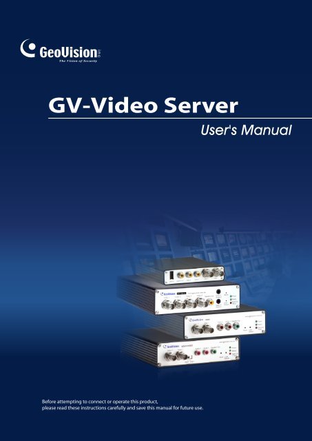
<strong>GV</strong>-<strong>Video</strong> <strong>Server</strong>User's ManualBefore attempting to connect or operate this product,please read these instructions carefully and save this manual for future use.
© 2009 GeoVision, Inc. All rights reserved.Under the copyright laws, this manual may not be copied, in whole or in part,without the written consent of GeoVision.Every effort has been made to ensure that the information in this manual isaccurate. GeoVision is not responsible for printing or clerical errors.GeoVision, Inc.9F, No. 246, Sec. 1, Neihu Rd.,Neihu District, Taipei, TaiwanTel: +886-2-8797-8377Fax: +886-2-8797-8335http://www.geovision.com.twTrademarks used in this manual: GeoVision, the GeoVision logo and <strong>GV</strong>series products are trademarks of GeoVision, Inc. Windows and Windows XPare registered trademarks of Microsoft Corporation.October 2009
PrefaceWelcome to the <strong>GV</strong>-<strong>Video</strong> <strong>Server</strong> User’s Manual.The <strong>GV</strong>-<strong>Video</strong> <strong>Server</strong> has a series of models designed to meet different needs. Eachmodel has its own firmware that can only be used on the specific model. This Manual isdesigned for the following models and firmware version:ModelFirmware Version<strong>GV</strong>-VS02 1.46<strong>GV</strong>-VS02A 1.01<strong>GV</strong>-VS04A 1.0<strong>GV</strong>-VS12 1.02For the users of <strong>GV</strong>-VS02, please note certain functions are only available for the units ofhardware version 2.0 or firmware version 1.46.This Manual provides an overview of the <strong>GV</strong>-<strong>Video</strong> <strong>Server</strong> and its accessories. Theinstructions will guide you through the installation and use of the <strong>GV</strong>-<strong>Video</strong> <strong>Server</strong> as well.i
ContentsChapter 1 Introduction ..........................................................11.1 Packing List..............................................................................................................11.1.1 <strong>GV</strong>-VS02.....................................................................................................11.1.2 <strong>GV</strong>-VS02A ..................................................................................................11.1.3 <strong>GV</strong>-VS12.....................................................................................................21.1.4 <strong>GV</strong>-VS04A ..................................................................................................21.2 System Requirement................................................................................................31.3 PoE Support.............................................................................................................31.4 GPS Support ............................................................................................................31.5 Options.....................................................................................................................41.6 Physical Description.................................................................................................51.6.1 Front View...................................................................................................51.6.2 Rear View ...................................................................................................9Chapter 2 Getting Started ...................................................132.1 Installing on a Network...........................................................................................132.2 Assigning an IP Address ........................................................................................132.3 Configuration Basics ..............................................................................................15Chapter 3 Accessing the <strong>GV</strong>-<strong>Video</strong> <strong>Server</strong> .......................163.1 Accessing Your Surveillance Images.....................................................................163.2 Functions Featured on the Main Page ...................................................................173.2.1 The Live View Window..............................................................................173.2.2 The Control Panel of the Live View Window.............................................193.2.3 Snapshot of a Live <strong>Video</strong> ..........................................................................203.2.4 <strong>Video</strong> Recording .......................................................................................203.2.5 Picture-in-Picture and Picture-and-Picture View.......................................203.2.6 Alarm Notification......................................................................................233.2.7 <strong>Video</strong> and Audio Configuration .................................................................243.2.8 Remote Configuration...............................................................................243.2.9 Camera Name Display..............................................................................253.2.10 Image Enhancement.................................................................................253.2.11 PTZ Control...............................................................................................263.2.12 Visual PTZ ................................................................................................27ii
3.2.13 I/O Control.................................................................................................283.2.14 Visual Automation .....................................................................................293.2.15 Network Status..........................................................................................29Chapter 4 Administrator Mode ...........................................304.1 <strong>Video</strong> & Motion.......................................................................................................324.1.1 Multicast....................................................................................................324.1.2 <strong>Video</strong> Settings...........................................................................................344.1.3 Motion Detection.......................................................................................384.1.4 Privacy Mask.............................................................................................394.1.5 Text Overlay..............................................................................................404.1.6 Tampering Alarm ......................................................................................414.1.7 Visual Automation .....................................................................................434.1.8 <strong>Video</strong> Channel Source Settings ................................................................444.2 Digital I/O & PTZ ....................................................................................................454.2.1 PTZ Settings .............................................................................................454.2.2 Input/Output Settings ................................................................................464.2.3 GPS/Wiegand ...........................................................................................484.2.4 Buzzer.......................................................................................................504.3 Events & Alerts.......................................................................................................514.3.1 E-mail........................................................................................................514.3.2 FTP ...........................................................................................................534.3.3 Center V2..................................................................................................554.3.4 VSM ..........................................................................................................574.3.5 <strong>GV</strong>-GIS .....................................................................................................594.3.6 Backup Center ..........................................................................................614.3.7 <strong>Video</strong> Gateway..........................................................................................634.3.8 ViewLog <strong>Server</strong>.........................................................................................644.3.9 3GPP ........................................................................................................644.4 Monitoring ..............................................................................................................654.5 Recording Schedule...............................................................................................664.5.1 Recording Schedule Settings....................................................................664.5.2 I/O Monitoring Settings .............................................................................674.6 Remote ViewLog....................................................................................................674.7 Network ..................................................................................................................684.7.1 LAN...........................................................................................................684.7.2 Wireless-Client Mode................................................................................704.7.3 Advanced TCP/IP .....................................................................................72iii
4.7.4 UMTS........................................................................................................744.7.5 Multicast....................................................................................................754.7.6 IP Filter......................................................................................................774.8 Management ..........................................................................................................784.8.1 Date and Time Settings ............................................................................784.8.2 GPS Maps Settings...................................................................................804.8.3 Storage Settings .......................................................................................814.8.4 User Account ............................................................................................834.8.5 Log Information.........................................................................................844.8.6 System Log ...............................................................................................844.8.7 Tools .........................................................................................................86Chapter 5 Recording and Playback ...................................875.1 Recording...............................................................................................................875.2 Playback.................................................................................................................875.2.1 Playback Using USB Mass Storage Device..............................................885.2.2 Playback Using Remote ViewLog.............................................................895.2.3 Playback of GPS Tracks ...........................................................................905.2.4 Playback of Daylight Saving Time Events ................................................92Chapter 6 Advanced Applications .....................................936.1 Upgrading System Firmware..................................................................................936.1.1 Using the Web Interface ...........................................................................946.1.2 Using the IP Device Utility.........................................................................956.2 Backing Up and Restoring Settings........................................................................966.2.1 Backing Up the Settings............................................................................966.2.2 Restoring the Settings...............................................................................976.3 GPS Tracking.........................................................................................................986.4 Restoring to Factory Default Settings...................................................................1006.5 Verifying Watermark.............................................................................................1016.5.1 Accessing AVI Files ................................................................................1016.5.2 Running Watermark Proof ......................................................................1016.5.3 The Watermark Proof Window................................................................102Chapter 7 DVR Configurations .........................................1037.1 Setting Up IP Cameras ........................................................................................104iv
7.2 Receiving Cardholder Data from <strong>Video</strong> <strong>Server</strong> ....................................................1087.3 Remote Monitoring with Multi View ......................................................................1097.4 Remote Monitoring with E-Map............................................................................111Chapter 8 CMS Configurations.........................................1138.1 Center V2 .............................................................................................................1138.2 VSM .....................................................................................................................1158.3 Dispatch <strong>Server</strong>....................................................................................................116Chapter 9 Auxiliary Device Connectors ..........................1179.1 <strong>GV</strong>-VS02, <strong>GV</strong>-VS02A and <strong>GV</strong>-VS04A.................................................................1179.1.1 Pin Assignment.......................................................................................1179.1.2 Relay Output...........................................................................................1189.2 <strong>GV</strong>-VS12 ..............................................................................................................1199.2.1 Pin Assignment.......................................................................................1199.2.2 RS-232 Terminal Block...........................................................................120Chapter 10 Mobile Phone Connection .............................12110.1 PDA ....................................................................................................................12210.1.1 Installing <strong>GV</strong>iew V2 ................................................................................12210.1.2 Activating the <strong>GV</strong>iew Function ...............................................................12310.1.3 Connecting to <strong>GV</strong>-<strong>Video</strong> <strong>Server</strong>.............................................................12310.1.4 Playing Back the Recordings from <strong>GV</strong>-<strong>Video</strong> <strong>Server</strong>.............................12410.1.5 Other Functions......................................................................................12610.2 Windows Smartphone ........................................................................................13110.2.1 Installing MSView V2 / V3 ......................................................................13110.2.2 Activating the MSView V2 / V3 Function................................................13110.2.3 Connecting to <strong>GV</strong>-<strong>Video</strong> <strong>Server</strong>.............................................................13210.2.4 Playing Back the Recordings from <strong>GV</strong>-<strong>Video</strong> <strong>Server</strong>.............................13410.2.5 Other Functions......................................................................................13410.3 Symbian Smartphone .........................................................................................13510.3.1 Installing SSView V3 ..............................................................................13510.3.2 Activating the SSView V3 Function........................................................13510.3.3 Connecting to <strong>GV</strong>-<strong>Video</strong> <strong>Server</strong>.............................................................13610.3.4 Quick Connection...................................................................................13610.3.5 Playing Back the Recordings from <strong>GV</strong>-<strong>Video</strong> <strong>Server</strong>.............................137v
10.3.6 Other Functions......................................................................................13710.4 3G Mobile Phone................................................................................................13810.4.1 Activating the 3G Mobile Phone Function ..............................................13810.4.2 Connecting to the <strong>GV</strong>-<strong>Video</strong> <strong>Server</strong>.......................................................13910.4.3 Playing Back the Recordings from <strong>GV</strong>-<strong>Video</strong> <strong>Server</strong>.............................140Specifications .......................................................................142<strong>Video</strong>.............................................................................................................................142Audio.............................................................................................................................142Management .................................................................................................................142Network.........................................................................................................................143Power over Ethernet .....................................................................................................143Connector......................................................................................................................143Appendix 145A. Supported Wireless LAN USB Adaptor................................................................145B. Supported Mobile Broadband Device...................................................................145C. Settings for Internet Explore 8..............................................................................146vi
1.1.3 <strong>GV</strong>-VS12Figure 1-31. AC Power Cord x 12. Power Adaptor x 13. I/O Cable with RJ-45 Connector x 14. Wall Hook x 15. Conical Anchor x 26. Screw x 47. Sticker (for positioning conical anchors) x 18. <strong>GV</strong>-<strong>Video</strong> <strong>Server</strong> Software DVD x 19. <strong>GV</strong>-<strong>Video</strong> <strong>Server</strong> User’s Manual x 11.1.4 <strong>GV</strong>-VS04AFigure 1-41. AC Power Cord x 12. DC Male-to-Male Connector x 13. Power Adaptor x 14. Wall Hook x 15. Conical Anchor x 46. Screw x 47. 3.5 mm Stereo to RCA Cable x 28. <strong>GV</strong>-<strong>Video</strong> <strong>Server</strong> Software DVD x 19. <strong>GV</strong>-<strong>Video</strong> <strong>Server</strong> User’s Manual x 110. DC 1 Male to 4 Female Cable (for camerapower supply from the <strong>GV</strong>-<strong>Video</strong> <strong>Server</strong>)-----Optional2
1Introduction1.2 System RequirementMicrosoft Internet Explorer 6.x or laterNote: For the users of Internet Explorer 8, it is required to configure the SecuritySettings. Without the settings, you cannot access the <strong>GV</strong>-<strong>Video</strong> <strong>Server</strong>. See Appendix C.1.3 PoE SupportThe models supporting PoE (Power over Ethernet) include:• <strong>GV</strong>-VS02 (Hardware Version 2.0), <strong>GV</strong>-VS02A, <strong>GV</strong>-VS12 and <strong>GV</strong>-VS04A.When the PoE (Power over Ethernet) function is used, please note:• The I/O terminal functions cannot work. Don’t connect any devices to the I/O terminalblock on the rear panel of the unit.• External power supply is required for USB storage device when used for recording.See “Power over Ethernet” in Specifications later in this manual before purchasing a PoEadaptor.1.4 GPS SupportAttached with the GPS receiver, the <strong>GV</strong>-<strong>Video</strong> <strong>Server</strong> allows you to perform vehicletracking on Google Maps. The models supporting GPS function include:• <strong>GV</strong>-VS02 (Hardware Version 2.0), <strong>GV</strong>-VS02A, <strong>GV</strong>-VS12 and <strong>GV</strong>-VS04AThe <strong>GV</strong>-GPS Receiver comes in two types of interfaces, UART and RS-232. Differentmodels of the <strong>GV</strong>-<strong>Video</strong> <strong>Server</strong> support different interfaces.• UART: <strong>GV</strong>-VS02 (Hardware Version 2.0), <strong>GV</strong>-VS02A and <strong>GV</strong>-VS04A• RS-232: <strong>GV</strong>-VS123
1.5 OptionsOptional devices can expand your <strong>GV</strong>-<strong>Video</strong> <strong>Server</strong>’s capabilities and versatility. Contactyour dealer for more information.<strong>GV</strong>-GPS Receiver<strong>GV</strong>-Reader<strong>GV</strong>-Relay V2<strong>GV</strong>-Storage System<strong>GV</strong>-GPS Receiver is a Global Position System receiver,allowing you to perform vehicle tracking and locationverification functions. It is available in two types ofinterfaces: UART and RS-232.<strong>GV</strong>-Reader includes transmit-receive antenna andelectronics. With both Wiegand and RS-485 outputs, it iscompatible with any standard access control panel.Working with this module, <strong>GV</strong>-<strong>Video</strong> <strong>Server</strong> can drive theloads of relay outputs over 5 volts.The iSCSI storage system allows you to record files overthe Internet.4
1Introduction1.6 Physical DescriptionThis section identifies the various components of the <strong>GV</strong>-<strong>Video</strong> <strong>Server</strong>.1.6.1 Front View1.6.1.1 <strong>GV</strong>-VS02Figure 1-5No. NameFunction1 <strong>Video</strong> Input 2 plugs for video inputs.2 <strong>Video</strong> Stream Switch3 Audio Input 2 plugs for audio inputs.The switch is designed for 2 cameras mode in live view.When the switch is set inVS01, dual streams of <strong>Video</strong> 1 are displayed.VS02, <strong>Video</strong> 1 and <strong>Video</strong> 2 are displayed simultaneously.Ensure to reboot the <strong>GV</strong>-<strong>Video</strong> <strong>Server</strong> after changing the setup.4 Speaker Output A plug for the speaker device.5 Reset Button6 Default ButtonIt reboots the <strong>GV</strong>-<strong>Video</strong> <strong>Server</strong>, and keeps all currentconfigurations.It resets all configurations to their factory settings. See 6.4Restoring to Factory Default Settings.7 Disk Full/Fault LED This LED is on, indicating the hard drive is full or faulty.8 Ready LEDThis LED is on, indicating the <strong>GV</strong>-<strong>Video</strong> <strong>Server</strong> is ready forconnection.9 Power LED This LED is on, indicating the power is supplied.5
1.6.1.2 <strong>GV</strong>-VS02A8761 2 3 4 5Figure 1-6No. NameFunction1 <strong>Video</strong> Input 2 plugs for video inputs.2 Audio Input 2 plugs for audio inputs.3 Speaker Output A plug for the speaker device.4 Reset Button5 Default ButtonIt reboots the <strong>GV</strong>-<strong>Video</strong> <strong>Server</strong>, and keeps all currentconfigurations.It resets all configurations to their factory settings. See 6.4Restoring to Factory Default Settings.6 Disk Full/Fault LED This LED is on, indicating the hard drive is full or faulty.7 Ready LEDThis LED is on, indicating the <strong>GV</strong>-<strong>Video</strong> <strong>Server</strong> is ready forconnection.8 Power LED This LED is on, indicating the power is supplied.6
1Introduction1.6.1.3 <strong>GV</strong>-VS12Figure 1-7No. NameFunction1 USB Port 1 USB port for installing the portable storage device.2 Speaker Output A plug for the speaker device.3 Audio Input 2 plugs for audio inputs.4 <strong>Video</strong> Input 2 plugs for video inputs.7
1.6.1.4 <strong>GV</strong>-VS04AFigure 1-8No. NameFunction1 <strong>Video</strong> Input 4 plugs for video inputs.2 Speaker Output A plug for the speaker device.3 Audio Input Each plug is for 2 audio inputs.4 Reset5 Default Button6Disk Full/FaultLED7 Ready LEDIt reboots the <strong>GV</strong>-<strong>Video</strong> <strong>Server</strong>, and keeps all currentconfigurations.It resets all configurations to their factory settings. See 6.4Restoring to Factory Default Settings.This LED is on, indicating the hard drive is full or faulty.This LED is on, indicating the <strong>GV</strong>-<strong>Video</strong> <strong>Server</strong> is ready forconnection.8 Power LED This LED is on, indicating the power is supplied.8
1Introduction1.6.2 Rear View1.6.2.1 <strong>GV</strong>-VS02Figure 1-9No. NameFunction1 USB Port 2 USB ports for installing portable storage devices.2 Ethernet PortA plug for inserting an Ethernet cable to build the networkconnection.3 Terminal BlockThe connectors for digital input, relay output, PTZ camera, Wieganddevice and GPS module control. See Chapter 9 Auxiliary DeviceConnectors.Note the GPS function is only available on <strong>GV</strong>-VS02 (HardwareVersion 2.0).4 Power In A plug for power input.5 Power OutA plug for power output. This power out can be used to power oncameras with a DC male to female power splitter cable (which is anoptional cable).9
1.6.2.2 <strong>GV</strong>-VS02AFigure 1-10No. NameFunction1 USB Port 2 USB ports for installing portable storage devices.2 Terminal BlockThe connectors for digital input, relay output, PTZ camera,Wiegand device and GPS module control. See Chapter 9 AuxiliaryDevice Connectors.3 Ethernet PortA plug for inserting an Ethernet cable to build the networkconnection.4 Power In A plug for power input.5 Power OutA plug for power output. This power out can be used to power oncameras by using a DC male to female power splitter cable (whichis not supplied).10
1Introduction1.6.2.3 <strong>GV</strong>-VS12Figure 1-11No. NameFunction1 Power In A plug for power input.2 Ethernet PortA plug for inserting an Ethernet cable to build the networkconnection.3 USB Port 1 USB port for installing the portable storage device.4 I/O / PTZ Port5RS-232Terminal Block6 Default Button7 Ready LEDA port for digital input, relay output and PTZ camera control. Insertthe I/O Cable with RJ-45 Connector to this port. See Chapter 9Auxiliary Device Connectors.The connectors for GPS module control. See Chapter 9 AuxiliaryDevice Connectors.It resets all configurations to their factory settings. See 6.4Restoring to Factory Default Settings.This LED is on, indicating the <strong>GV</strong>-<strong>Video</strong> <strong>Server</strong> is ready forconnection.8 Power LED This LED is on, indicating the power is supplied.11
1.6.2.4 <strong>GV</strong>-VS04AFigure 1-12No. NameFunction1 USB Port 2 USB ports for installing portable storage devices.2 Terminal BlockThe connectors for digital input, relay output, PTZ camera,Wiegand device and GPS module control. See Chapter 9 AuxiliaryDevice Connectors.3 Ethernet PortA plug for inserting an Ethernet cable to build the networkconnection.4 Power In A plug for power input.5 Power OutA plug for power output. This power out can be used to power oncameras by using a DC male to female power splitter cable (whichis an optional accessory).12
2Getting StartedChapter 2 Getting StartedThis section provides basic information to get the <strong>GV</strong>-<strong>Video</strong> <strong>Server</strong> working on the network.2.1 Installing on a NetworkThese instructions describe the basic connections to install the <strong>GV</strong>-<strong>Video</strong> <strong>Server</strong> on thenetwork. Here we use <strong>GV</strong>-VS02 as the example to demonstrate the steps.1 23 4Figure 2-11. Connect your camera’s video output to the BNC video input.2. Connect your audio source to the RCA audio input.3. Connect the hub or switch on the LAN to the unit’s 10/100 Mbps port.4. Connect the power supply to the power input.5. Wait until both Power and Ready LEDs are on and then you can set the IP address forthe unit.2.2 Assigning an IP AddressDesigned for use on the network, the <strong>GV</strong>-<strong>Video</strong> <strong>Server</strong> must be assigned an IP address tomake it accessible.Note: The <strong>GV</strong>-<strong>Video</strong> <strong>Server</strong> has a default address of 192.168.0.10. The computer used toset the IP address must be under the same network or IP sequence assigned to the unit.13
1. Open your web browser, and type the default IP address http://192.168.0.102. In both Login and Password fields, type the default value admin. Click Apply.3. In the left menu, select Network and then LAN to begin the network settings.Figure 2-24. Select Static IP address. Type IP Address, Subnet Mask, Router/Gateway, PrimaryDNS and Secondary DNS in the Configure connection parameters section.5. Click Apply. The <strong>GV</strong>-<strong>Video</strong> <strong>Server</strong> is accessible by entering the assigned IP addresson the web browser.IMPORTANT:• Dynamic IP Address and PPPoE should only be enabled if you know which IPaddress the <strong>GV</strong>-<strong>Video</strong> <strong>Server</strong> will get from the DHCP server or ISP. Otherwise,you must use the Dynamic DNS service to obtain a domain name linked to the<strong>GV</strong>-<strong>Video</strong> <strong>Server</strong>’s changing IP address first.For details on Dynamic DNS <strong>Server</strong> settings, see 4.7.3 Advanced TCP/IP.• If Dynamic IP Address and PPPoE is enabled and you cannot access the unit,you may have to reset it to the factory default settings and then perform thenetwork settings again.To restore the factory settings, see the Default button in 1.5.1 Front View.14
2Getting Started2.3 Configuration BasicsOnce the <strong>GV</strong>-<strong>Video</strong> <strong>Server</strong> is properly installed, the following important features can beconfigured using the browser-based configuration page and are discussed in the followingsections in this manual:• Date and time adjustment: see 4.8.1 Date and Time Settings.• Login and privileged passwords: see 4.8.4 User Account.• Network gateway: see 4.7 Network.• Camera image adjustment: see 3.2.2 The Control Panel of the Live View Window.• <strong>Video</strong> format, resolution and frame rate: see 4.1.2 <strong>Video</strong> Settings.15
Chapter 3 Accessing the <strong>GV</strong>-<strong>Video</strong> <strong>Server</strong>Two types of users are allowed to log in the <strong>GV</strong>-<strong>Video</strong> <strong>Server</strong>: Administrator and Guest.The Administrator has unrestricted access to all system configurations, while the Guesthas the access to live images and network status only.3.1 Accessing Your Surveillance ImagesOnce installed, your <strong>GV</strong>-<strong>Video</strong> <strong>Server</strong> is accessible on a network. Follow these steps toaccess your surveillance images:1. Start the Internet Explorer browser.2. Enter the IP address or domain name of the <strong>GV</strong>-<strong>Video</strong> <strong>Server</strong> in theLocation/Address field of your browser.Figure 3-13. Enter the login name and password.• The default login name and password for Administrator are admin.• The default login name and password for Guest are guest.4. A video image, similar to the example in Figure 3-2, is now displayed in your browser.Note: To enable the updating of images in Microsoft Internet Explorer, you must set yourbrowser to allow ActiveX Controls and perform a once-only installation of GeoVision’sActiveX component onto your computer.16
3Accessing the <strong>GV</strong>-<strong>Video</strong> <strong>Server</strong>3.2 Functions Featured on the Main PageThis section introduces the features of the Live View window and Network Status on themain page. The two features are accessible by both Administrator and Guest.Main Page of Guest Mode▼ <strong>Video</strong> and Motion▼ Live View► Camera 1► Camera 2► 2 Cameras▼ Network► StatusFigure 3-23.2.1 The Live View WindowIn the left menu, click Live View, and then select Camera 1, Camera 2 or 2 Cameras tosee the live video.Note: To have the dual streaming of Camera 1, the <strong>Video</strong> Stream Switch on the unitshould be set to VS01. Note this function is only available on <strong>GV</strong>-VS02.17
1110981 2 3 4 5 6 7Figure 3-3No. NameFunction1 Play Plays live video.2 Stop Stop playing video.3 Microphone Talks to the surveillance area from the local computer.4 Speaker Listens to the audio around the camera.5 Snapshot Takes a snapshot of live video. --- See 3.2.3 Snapshot of a Live <strong>Video</strong>.6 File Save Records live video to the local computer. --- See 3.2.4 <strong>Video</strong> Recording.Switches to full screen view. Right-click the image to have these7 Full Screen options: Snapshot, PIP, PAP, Zoom In and Zoom Out.--- See 3.2.5 Picture-in-Picture and Picture-and-Picture View.Starts the I/O Control Panel or the Visual Automation.8 I/O Control--- See 3.2.13 I/O Control.Starts the PTZ Control Panel and the Visual PTZ.9 PTZ Control--- See 3.2.11 PTZ Control and 3.2.12 Visual PTZ.10 Change Camera Sets the desired camera for display.Brings up these functions: Alarm Notify, <strong>Video</strong> and AudioConfiguration, Remote Config, Show Camera Name and Image11 Show System Menu Enhance. --- See 3.2.6 Alarm Notification, 3.2.7 <strong>Video</strong> and AudioConfiguration, 3.2.8 Remote Configuration, 3.2.9 Camera Name Displayand 3.2.10 Image Enhancement respectively.18
3Accessing the <strong>GV</strong>-<strong>Video</strong> <strong>Server</strong>3.2.2 The Control Panel of the Live View WindowTo open the control panel of the Live View window, click the arrow button on top of theviewer. You can access the following functions by using the right and left arrow buttons onthe control panel.Click the arrow button to display the control panel.Click the right and leftarrow buttons to changethe page of the controlpanel.Figure 3-4[Information] Displays the version of the <strong>Video</strong> <strong>Server</strong>, local time of the local computer,host time of the <strong>Video</strong> <strong>Server</strong>, and the number of users logging in to the <strong>Video</strong> <strong>Server</strong>.[<strong>Video</strong>] Displays the current video codec, resolution and data rate.[Audio] Displays the audio data rates when the microphone and speaker devices areenabled.[I/O Control] Provides a real-time graphic display of the input and output status. You canforce the output to be triggered by double-clicking its icon.[Alarm Notify] Displays the captured images by sensor triggers and/or motion detection.For this function to work, you must configure the Alarm Notify settings first. See 3.2.6Alarm Notification.[Camera Adjustment] Allows you to adjust the image quality.[GPS] For details see 6.3 GPS Tracking.[Download] Allows you to install the programs from the hard drive.19
3.2.3 Snapshot of a Live <strong>Video</strong>To take a snapshot of live video, follow these steps:1. Click the Snapshot button (No. 5, Figure 3-3). The Save As dialog box appears.2. Specify Save in, type the File name, and select JPEG or BMP as Save as Type. Youmay also choose whether to display the name and date stamps on the image.3. Click the Save button to save the image in the local computer.3.2.4 <strong>Video</strong> RecordingYou can record live video for a certain period of time to your local computer.1. Click the File Save button (No. 6, Figure 3-3). The Save As dialog box appears.2. Specify Save in, type the File name, and move the Time Period scroll bar to specifythe time length of the video clip from 1 to 5 minutes.3. Click the Save button to start recording.4. To stop recording, click the Stop button (No. 2, Figure 3-3).3.2.5 Picture-in-Picture and Picture-and-Picture ViewThe full screen mode provides two types of close-up views: Picture-in-Picture (PIP) andPicture-and Picture (PAP). The two views are useful to provide clear and detailed imagesof the surveillance area.To access this feature:• Click the Full Screen button (No. 7, Figure 3-3). Right-click the full screen to have theoptions of PIP and PAP.• Right-click the live view to have the options of PIP and PAP.20
3Accessing the <strong>GV</strong>-<strong>Video</strong> <strong>Server</strong>Picture-in-Picture ViewWith the Picture in Picture (PIP) view, you can crop the video to get a close-up view orzoom in on the video.Navigation boxInset windowFigure 3-51. Select PIP. An inset window appears.2. Click the insert window. A navigation box appears.3. Move the navigation box around in the inset window to have a close-up view of theselected area.4. To adjust the navigation box size, move the cursor to any of the box corners, andenlarge or diminish the box.5. To exit the PIP view, right-click the image and click PIP again.21
Picture-and-Picture ViewWith the Picture and Picture (PAP) view, you can create a split video effect with multipleclose-up views on the image. A total of 7 close-up views can be defined.Figure 3-61. Select PAP. A row of three inset windows appears at the bottom.2. Draw a navigation box on the image, and this selected area is immediately reflectedin one inset window. Up to seven navigation boxes can be drawn on the image.3. To adjust a navigation box size, move the cursor to any of the box corners, andenlarge or diminish the box.4. To move a navigation box to another area on the image, drag it to that area.5. To change the frame color of the navigation box or hide the box, right-click the image,select Mega Pixel Setting and click one of these options:• Display Focus Area of PAP Mode: Displays or hides the navigation boxes onthe image• Set Color of Focus Area: Changes the color of the box frames.6. To delete a navigation box, right-click the desired box, select Focus Area of PAPMode and click Delete.7. To exit the PAP view, right-click the image and click PAP again.22
3Accessing the <strong>GV</strong>-<strong>Video</strong> <strong>Server</strong>3.2.6 Alarm NotificationAfter input triggers and motion detection, you can be alerted by a pop-up live video andview up to four captured images.Pop-up live videoCaptured imagesFigure 3-7To configure this function, click the Show System Menu button (No. 11, Figure 3-3), andselect Alarm Notify. This dialog box appears.Figure 3-8• Motion Notify: Once motion is detected, the captured images are displayed on thecontrol panel of the Live View window.• I/O Alarm Notify: Once the input device is triggered, the captured images aredisplayed on the control panel of the Live View window. For this function to work, theAdministrator needs to install the input device properly. See 4.2.2 Input/OutputSettings.• Alert Sound: Activates the computer alarm on motion and input-triggered detection.• IE Window Pops up: The minimized Live View window pops up on motion and inputtriggereddetection.23
• Auto Snapshot: The snapshot of live video is taken every 5 seconds on motion andinput-triggered detection.• File Path: Assigns a file path to save the snapshots.3.2.7 <strong>Video</strong> and Audio ConfigurationYou can enable the microphone and speaker for two-way audio communication and adjustthe audio volume. To change audio configuration, click the Show System Menu button(No. 11, Figure 3-3), and select <strong>Video</strong> and Audio Configuration.Figure 3-93.2.8 Remote ConfigurationYou can view the connection status of the central monitoring stations and upgradefirmware over the Internet. Click the Show System Menu button (No. 11, Figure 3-3), andselect Remote Config. The Remote Config dialog box will appear.[Status] In this tab, you can see the current status of the connection to Center V2 andVSM.[Firmware Upgrade] In this tab, you can upgrade the firmware over the network. Fordetails, see Chapter 6 Advanced Applications.24
3Accessing the <strong>GV</strong>-<strong>Video</strong> <strong>Server</strong>3.2.9 Camera Name DisplayTo display the camera name on the image, click the Show System Menu button (No. 11,Figure 3-3), and select Show Camera Name.3.2.10 Image EnhancementTo enhance the image quality of live video, click the Show System Menu button (No. 11,Figure 3-3), and select Image Enhance. This dialog box appears.Figure 3-10• De-Interlace: Coverts the interlaced video into non-interlaced video.• De-Block: Removes the block-like artifacts from low-quality and highly compressedvideo.• Enable DirectDraw: Activates the DirectDraw function.25
3.2.11 PTZ ControlTo open the PTZ control panel, click the PTZ Control button (No. 9, Figure 3-3) and selectPTZ Control Panel. Different PTZ devices have different functions, so the featuresincluded in the Option button may vary.This feature is only available when the PTZ is set ahead by the Administrator. For details,see 4.2.1 PTZ Settings.ExitPan / Tilt ControlZoomFigure 3-11FocusOption (Settings for Auto Mode,Preset, Port, Speed and etc.)Preset Switch Panel26
3Accessing the <strong>GV</strong>-<strong>Video</strong> <strong>Server</strong>3.2.12 Visual PTZIn additional to the PTZ control panel, you can display a visual PTZ control panel on theimage. This feature is only available when the PTZ is set ahead by the Administrator. Fordetails, see 4.2.1 PTZ Settings.Figure 3-12‣ To access this feature, click the PTZ Control button (No. 9, Figure 3-3) and selectVisual PTZ.‣ To change the panel settings, click the green PTZ button on the top left corner. Youwill have these options:[PTZ Control Type]• Type 1: In this mode when you place the mouse arrow on the four directions, i.e.north, south, east, west, the speed indicator of five levels will appear. Click andhold on the required level of movement and the camera will move as per thespecific speed.• Type 2: In this mode with the mouse click, the PTZ control panel will appear. Themovement of the camera will depend on the speed of the mouse movement.[Configure]• Set Color: Changes the color of the panel. Three kinds of colors are available:Red, Green and Blue.• Transparent Degree: Adjusts the transparency level of the panel. Ten levelsrange from 10% (fully transparent) to 100% (fully opaque).27
3.2.13 I/O ControlThe I/O Control window provides real-time graphic displays of camera and I/O status, andalarm events. Additionally, you can force output to be triggered.Figure 3-13‣ To display the I/O control window, click the I/O Control button (No. 8, Figure 3-3).‣ The Alarm List is displayed in three levels. The first level indicates date, the secondindicates time, and the third indicates alarm ID. Clicking the Reset button will clear thelist.‣ To trigger an output device, highlight an output and then click the Output button.28
3Accessing the <strong>GV</strong>-<strong>Video</strong> <strong>Server</strong>3.2.14 Visual AutomationThe Visual Automation allows you to change the current state of the electronic device bysimply clicking on its image, e.g. turning the light ON. This feature is only available whenthe Visual Automation is set ahead by the Administrator. For details, see 4.1.7 VisualAutomation.Figure 3-14‣ To access this feature, click the I/O Control button (No. 8, Figure 3-3) and selectVisual Automation.‣ To change the style of the set areas, click the green I/O button on the top left corner.You will have these options:• Show All: Displays all set areas.• Rect Float: Embosses all set areas.• Set Color: Changes the frame color of all set areas3.2.15 Network StatusTo view the network status, in the left menu, click Network and select Status.Figure 3-1529
Chapter 4 Administrator ModeThe Administrator can access the system configuration via the Internet. Eight categories ofconfigurations are involved in the system configuration: <strong>Video</strong> and Motion, Digital I/Oand PTZ, Events and Alerts, Monitoring, Recording Schedule, Remote ViewLog,Network, and Management.▼ <strong>Video</strong> and Motion► Live View► <strong>Video</strong> Settings► Motion Detection► Privacy Mask► Text Overlay► Tampering Alarm► Visual Automation► <strong>Video</strong> Channel Source Settings▼ Digital I/O and PTZ► I/O Control► PTZ Settings► GPS/Wiegand► Buzzer▼ Events and Alerts► Email► FTP► Center V2► VSM► <strong>GV</strong>-GIS► Backup Center► <strong>Video</strong> Gateway► ViewLog► 3GPP▼ Monitoring▼ Recording Schedule►Camera►I/O Monitor▼ Remote ViewLog▼ Network► Status► LAN► Wireless► Advanced TCP/IP► UMTS► Multicast► IP Filtering▼ Management► Date and Time► GPS Maps Settings► Storage Settings Figure 4-1► User Account► Log Information► Tools30
4Administrator ModeComparison Table for Major FunctionsThe options or functions on the left menu of the Web interface (Figure 4-1) may varydepended on models. The table below provides the information of major differences insupported functions.ModelFunction<strong>GV</strong>-VS02(Firmware V1.46)<strong>GV</strong>-VS02A(Firmware V1.01or later)<strong>GV</strong>-VS04A(Firmware V1.0or later)<strong>GV</strong>-VS12(Firmware V1.02or later)Wiegand Yes Yes Yes NoBuzzer No Yes Yes NoMulticast Yes Yes Yes NoTampering Alarm No Yes Yes YesWatermark No Yes Yes Yes<strong>Video</strong> ChannelSource SettingsNo Yes Yes NoSystem Log No Yes Yes YesBackup Center No Yes Yes Yes<strong>Video</strong> Gateway No Yes Yes YesGIS with TwoConnectionsNo Yes Yes YesText Overlay No Yes Yes YesNote: The Watermark option is included in the <strong>Video</strong> Settings page.31
4.1 <strong>Video</strong> & MotionThis section includes the video image settings and introduces how the images can bemanaged by using Multicast, Motion Detection, Privacy Mask, Tampering Alarm, VisualAutomation and <strong>Video</strong> Channel Source Settings.4.1.1 MulticastNote this function is only available on <strong>GV</strong>-VS02 (Firmware Version 1.46 or later), <strong>GV</strong>-VS02A (Firmware Version 1.01 or later) and <strong>GV</strong>-VS04A.The Multicast view allows the <strong>GV</strong>-<strong>Video</strong> <strong>Server</strong> receiving video and audio streams from amulticast group. It also enables the <strong>GV</strong>-<strong>Video</strong> <strong>Server</strong> to receive audio broadcast from thehosts in the multicast group.To join a multicast group and listen to audio broadcasting, it is required to activate therelated settings in 4.7.5 Mulitcast.Host ListFigure 4-2Configure Button1. The host(s), in the multicast group, is displayed automatically on the host list. If youcannot see any host displayed, click the Configure button, select General Setup, selectMulticast and ensure the relevant IP address, port number and network card arecorrectly configured.2. Expand the Host folder and drag the desired cameras to the screen for display. If the hosthas already set a password, you will be promoted to enter it at this step.32
4Administrator Mode3. To receive audio broadcasting, first ensure a speaker is properly installed on the localcomputer. Then click the Configure button, select General Setup, select Receivebroadcast audio, and ensure the broadcast IP address and port number are correctlyconfigured.4. To save the current settings of screen division and camera display for future use, clickthe Configure button, select <strong>Video</strong> List Setup, and select Export. You can also selectImport to apply the pre-defined settings.33
4.1.2 <strong>Video</strong> SettingsFigure 4-334
4Administrator Mode[Name]Rename the camera. The camera name will appear on the Live View. To display thecamera name, see 3.2.9 Camera Name Display.[Connection Template]Select the type of your network connection. Unless you select Customized, this option willautomatically bring up the recommended video resolution, frame rate, bandwidth and GOPsize.Due to the bandwidth limitation for mobile phone connections, only the video resolutions360 x 240 (360 x 288) and 176 x 122 (176 x 144) are supported. The higher resolution youselect, the higher frame rate or better video quality you will get. But note that your mobilephone must support the video resolution you wish to select.Connection templates for mobile phone connections:<strong>GV</strong>iew V2 SupportedResolutionFrame RateNTSC 360 x 240 15PAL 360 x 288 12.53GPPv7, Msview V2, Msview V3, Ssview V3 and <strong>GV</strong>iew V2 SupportedResolutionFrame RateNTSC 360 x 240 7.5PAL 360 x 288 83GPPv6, Msview V2, Msview V3, Ssview V3 and <strong>GV</strong>iew V2 SupportedResolutionFrame RateNTSC 176 x 112 5PAL 176 x 144 535
[<strong>Video</strong> Signal Type]• Auto detect signal type on booting: Automatically detects the type of video input isNTSC or PAL.The supported codecs vary from model to model.ModelCodec<strong>GV</strong>-VS02MPEG4<strong>GV</strong>-VS02AMPEG4<strong>GV</strong>-VS04AMPEG4<strong>GV</strong>-VS12 MPEG4 , MJPEG, H.264Note: The Main Streaming Type drop-down list is only available for <strong>GV</strong>-VS12.There are 4 options for selecting image resolutions.NTSCPAL720 x 480 720 x 576720 x 480 De-interlaced 720 x 576 De-interlaced360 x 240 360 x 288176 x112 176 x 144Several frame rates are available.Format Frame RateNTSC 1, 2, 3, 5, 7.5, 10, 15, 30PAL 1, 2.5, 5, 8, 12.5, 25[Bandwidth Management]When using MPEG-4 or H.264, it is possible to control the bitrate, which in turn allows theamount of bandwidth usage to be controlled.• VBR (Variable Bitrate): The quality of the video stream is kept as constant aspossible at the cost of a varying bitrate. The bandwidth is much more efficiently usedthan a comparable CBR.Set the image quality to one of the 3 standards: Fair, Good, and Excellent.• CBR (Constant Bitrate): CBR is used to achieve a specific bitrate by varying thequality of the stream. The bitrates available for selection depend on the imageresolution.36
4Administrator ModeModel<strong>GV</strong>-VS02<strong>GV</strong>-VS02A<strong>GV</strong>-VS04A<strong>GV</strong>-VS12Bitrates for selection3072 kbps, 2048 kbps, 1536 kbps, 1024 kbps, 768 kbps,512 kbps, 384 kbps, 256 kbps (3GPPV7),128 kbps (3GPPV7) , 64 kbps (3GPPV6) and52 kbps (3GPPV6)2048 kbps, 1536 kbps, 1024 kbps, 768 kbps,512 kbps, 384 kbps, 256 kbps (3GPPV7),128 kbps (3GPPV7) , 64 kbps (3GPPV6) and52 kbps (3GPPV6)[GOP Structure and Length]Set the maximum number of frames in a GOP structure (the GOP size limit). This functionis only available when you select Customized in the Connection Template section.[Alarm Settings]The alarm settings allow you to capture images before and/or after the motion or I/O eventhappens.• Pre-alarm recording time: Activates video recording before an event occurs. Set therecording time to 1 or 2 seconds.• Post-alarm recording time: Activates video recording onto the attached USB massstorage device after an event occurs. Set the recording time from 1 to 30 seconds.• Split Interval: Sets the time length between each event file from 1 to 5 minutes.• Record Audio: Activates audio recording when an event occurs.• Overlaid with camera name: Includes camera names on live and recorded videos.• Overlaid with date stamps: Includes date stamps on live and recorded videos.• Overlaid with time stamps: Includes time stamps on live and recorded videos.• Overlaid with digital input description name: Includes the names of selected inputson live and recorded videos.[Watermark] Enable this option to watermark all recordings. The watermark allows you toverify whether the video has been tampered while it was recorded and saved. See 6.5Verifying Watermark.[Apply All Settings]• Apply the settings to all cameras: Applies the same settings to the other camera.37
4.1.3 Motion DetectionMotion detection is used to generate an alarm whenever movement occurs in the videoimage. You can configure up to 8 areas with different sensitivity values for motiondetection.Figure 4-41. The default sensitivity value is 2 for the whole area. To define a different sensitivityvalue, click Reset.2. Select the desired sensitivity by moving the slider. There are three values. The higherthe value, the more sensitive the camera is to motion.3. Drag an area on the image. Click Add when you are prompted to confirm the setting.4. To create several areas with different sensitivity values, repeat Steps 2 and 3.5. Click Save to save the above settings.6. To trigger the alarm outputs when motion is detected, select the outputs (Output 1 toOutput 4) and click the Apply button. To activate the output settings, you must alsostart Camera monitoring manually or by schedule. For related settings, see 4.4Monitoring.Note: For <strong>GV</strong>-VS12 users, this function does not work when MJPEG is selected as thecodec in the <strong>Video</strong> Signal Type field (Figure 4-1). For details, see 4.1.2 <strong>Video</strong> Settings.38
4Administrator Mode4.1.4 Privacy MaskThe Privacy Mask can block out sensitive areas from view, covering the areas with darkboxes in both live view and recorded clips. This feature is ideal for locations with displays,keyboard sequences (e.g. passwords), and for anywhere else you don’t want sensitiveinformation visible.Figure 4-51. Select the Enable option.2. Drag the area(s) where you want to block out on the image. Click Add when you areprompted to confirm the setting.3. Click the Save button to save all the settings.39
4.1.5 Text OverlayNote this option is only available on <strong>GV</strong>-VS02A (Firmware Version 1.01 or later), <strong>GV</strong>-VS04A and <strong>GV</strong>-VS12 (Firmware Version 1.02 or later).The Text Overlay function allows you to type any text in any place on the camera view. Upto 16 text messages can be created. The overlaid text will also be saved in the recordedimages.Figure 4-61. Select the Enable option.2. Click any place on the image. This dialog box appears.Figure 4-73. Type the desired text, and click OK. The text is overlaid on the image.4. Click on the text and drag it to any place on the image.5. Click Set Font to modify the font style of the text.6. Click Save to apply the settings, or click Load (Undo) to revert to a previous setting.40
4Administrator Mode4.1.6 Tampering AlarmNote this option is only available on <strong>GV</strong>-VS02A (Firmware Version 1.01 or later), <strong>GV</strong>-VS04A and <strong>GV</strong>-VS12 (Firmware Version 1.02 or later).The Tampering Alarm is used to detect when a camera is being physically tampered. Analarm can be generated when the camera is moved, covered up, or out of focus. Thealarm approaches include the triggered output device, e-mail alert and system buzzer. Tohave the tampering alarm, first set up these alarm approaches properly:• To trigger the output device when a tamper event occurs, enable the output setting andselect Tampering Alarm for the related camera. See Output Setting in 4.2.2Input/Output Settings.• To trigger the e-mail alert when a tamper event occurs, enable the e-mail setting andselect Tampering Alarm for the related camera. See 4.3.1 E-Mail.• To trigger the system buzzer when a tamper event occurs, enable the buzzer setting.See 4.2.4 Buzzer.Figure 4-841
To configure the tampering alarm:1. Select the Enable option.2. If you want <strong>GV</strong>-<strong>Video</strong> <strong>Server</strong> to ignore any movement or scene change in certainareas, click the button to drag areas on the camera view.3. Select the desired detection sensitivity by moving the slider. The higher the value, themore sensitive the camera is to scene changes.4. In the Tolerance Time of Alarm field, specify the time length allowed for scenechanges before an alarm is generated.5. In the Duration of Alarm field, specify the duration of the alarm after which thetriggered output device or system buzzer will be turned off.6. To trigger an alarm when the scene turns dark, e.g. the lens of camera has beencovered, select Alarm for Dark Images.7. Click Apply to save all the settings.8. Start monitoring to enable the function. To have buzzer alarm, it is required to startthe Camera monitoring. To have output alarm, it is required to start Input monitoring.For these two types of monitoring, see 4.4 Monitoring.When the camera has been tampered, the output device and system buzzer can beactivated. To turn off the output device and system buzzer immediately, return to thissetting page, and click Restart Detection.Note: <strong>GV</strong>-VS12 does not support the system buzzer.42
4Administrator Mode4.1.7 Visual AutomationThis intuitive feature helps you automate any electronic device by triggering the connectedoutput device. When you click on the image of the electronic device, you can simplychange its current state, e.g. light ON.1. Select the Enable option.Figure 4-92. Drag an area on the image of the electronic device. This dialog box appears.Figure 4-103. Assign the connected module and output device. In the Note filed, type a note to helpyou manage the device. Click OK to save the settings.4. To change the frame color of the set area, click the Set Color button.5. To emboss the set area, select Float Up; or keep it flat by selecting Normal.6. Click the Save Set button to apply the settings.To perform the function, see 3.2.14 Visual Automation.43
4.1.8 <strong>Video</strong> Channel Source SettingsNote this option is only available for <strong>GV</strong>-VS02A (Firmware Version 1.01 or later) and <strong>GV</strong>-VS04A.The function allows you to assign the video input to the desired video channel for display.Figure 4-1144
4Administrator Mode4.2 Digital I/O & PTZFor auxiliary device control, you can find one I/O / PTZ port along with one RS-232terminal block for GPS control on the rear panel of <strong>GV</strong>-VS12 (see Figure 1-9). Differently,on the rear panels of <strong>GV</strong>-VS02, <strong>GV</strong>-VS02A and <strong>GV</strong>-VS04A, all the functions for auxiliarydevice control are included in a 16-pin terminal block. For details, see Chapter 9 AuxiliaryDevice Connectors.The connectors for all terminal blocks on all models and the I/O / PTZ port on the <strong>GV</strong>-VS12 can be divided into four categories based on the interface being used:1. Digital Input / Relay Output2. RS-485 interface for PTZ control3. Wiegand interface for access control(available on <strong>GV</strong>-VS02, <strong>GV</strong>-VS02A and <strong>GV</strong>-VS04A)4. GPS interface for vehicle tracking:• UART: available on <strong>GV</strong>-VS02 (Hardware Version 2.0), <strong>GV</strong>-VS02A and <strong>GV</strong>-VS04A• RS-232: available on <strong>GV</strong>-VS124.2.1 PTZ SettingsThrough the RS-485 interface on the I/O terminal block, you can connect 2 to 4 PTZcameras depended on models. Before adding a PTZ camera to the <strong>GV</strong>-<strong>Video</strong> <strong>Server</strong>, youmust install the PTZ components from the Software DVD by selecting Install PTZ on theinstallation menu. Then open this PTZ Settings page to configure the baud rate, speedand address. For these settings, please consult your PTZ documentation.Figure 4-12Note: Currently the <strong>GV</strong>-<strong>Video</strong> <strong>Server</strong> doesn’t support the PTZ camera with RS-232interface.45
4.2.2 Input/Output SettingsInput SettingThe number of input devices the <strong>GV</strong>-<strong>Video</strong> <strong>Server</strong> can connect to vary from model tomodel. <strong>GV</strong>-VS02, <strong>GV</strong>-VS02A and <strong>GV</strong>-VS04A connect up to 4 input devices; <strong>GV</strong>-VS12connects up to 2 input devices.Figure 4-13• Normal State: Set up the input state to trigger actions by selecting Open Circuit (N/O)or Grounded Circuit (N/C).• Latch Mode: Enable the mode to have a momentary output alarm.• Trigger Digital Output Relay: Select the output(s) to be triggered once the input isactivated.• Record: Select the camera(s) to start recording once the input is activated.• Send <strong>Video</strong> to Center V2: Select the camera(s) to send their images to Center V2when the input is triggered.You can direct a PTZ camera to a preset point upon input trigger:• Set PTZ camera to preset point: Enable the preset function and select the camerathat represents the PTZ camera.• Input on: Direct the PTZ camera to a preset point when the input is triggered.• Input off: Direct the PTZ camera to another preset point when the triggered input isoff.46
4Administrator Mode• Duration to set preset after input off x seconds: Specify the amount of time thePTZ camera stays in “Input on” preset point before moving to “Input off” preset point.Note: The input settings only function after you start Input monitoring manually or byschedule. To configure the input monitoring, see 4.4 Monitoring.For related PTZ settings, see 4.2.1 PTZ Settings.Output SettingThe number of output devices the <strong>GV</strong>-<strong>Video</strong> <strong>Server</strong> can connect to vary from model tomodel. <strong>GV</strong>-VS02, <strong>GV</strong>-VS02A and <strong>GV</strong>-VS04A connect up to 4 output devices; <strong>GV</strong>-VS12connects up to 2 output devices.Figure 4-14Select Enable to enable the output device. Choose the output signal that mostly suits thedevice you are using: N/O (Open Circuit), N/C (Grounded Circuit), N/O Toggle, N/C Toggle,N/O Pulse or N/C Pulse. For Toggle output type, the output will keep going on once it istriggered until the next trigger. For Pulse output type, the output is triggered for theamount of time you specify in the Trigger Pulse Mode for x Seconds field.• Alarm Settings:Note this option is only available for <strong>GV</strong>-VS02A, <strong>GV</strong>-VS04A and <strong>GV</strong>-VS12.You can choose to automatically activate the configured output device for alarm underthese conditions: video lost, tampering alarm, disk write error (Rec Error) and hard disk full(HD Full).47
4.2.3 GPS/WiegandYou can select either GPS or Wiegand function for use. The two functions cannot beenabled at the same time.Figure 4-15GPS FunctionNote this function is only available for <strong>GV</strong>-VS02 (Hardware Version 2.0), <strong>GV</strong>-VS02A, <strong>GV</strong>-VS04A and <strong>GV</strong>-VS12.To enable the GPS function, a <strong>GV</strong>-GPS module or any GPS module supporting UART orRS-232 interface is required to connect to the <strong>GV</strong>-<strong>Video</strong> <strong>Server</strong> first. See Chapter 9Auxiliary Device Connectors.• Select GPS Baudrate: Two baud rate options are available: 4800 and 9600. Bydefault the value is 9600.• Set GPS Update Frequency: Set the update frequency in seconds for GPS data.After the GPS function is activated, you can view the location of the <strong>GV</strong>-<strong>Video</strong> <strong>Server</strong> onGoogle Maps. See 6.3 GPS Tracking. If the monitoring is also activated, the GPS trackingroutes will be recorded along with videos. This makes it possible to play back trackingroutes and videos together on <strong>GV</strong>-System. See 5.2.3 Playback of GPS Tracking Routes.48
4Administrator ModeWiegand FunctionNote this function is only available for <strong>GV</strong>-VS02, <strong>GV</strong>-VS02A and <strong>GV</strong>-VS04A.The <strong>GV</strong>-<strong>Video</strong> <strong>Server</strong> can work in conjunction with the Wiegand-interface card reader tosend video and cardholder data to the central monitoring stations Center V2 and VSM, aswell as <strong>GV</strong>-System (DVR). Moreover, the Wiegand port on the <strong>GV</strong>-<strong>Video</strong> <strong>Server</strong> can beused as an input to activate recording once the card reader is triggered or a valid card ispresent to the card reader.The output format of Wiegand supported by the <strong>GV</strong>-<strong>Video</strong> <strong>Server</strong> is HID standard 26 bitsand 37 bits.TCP / IPWiegand InText DataCard Reader<strong>GV</strong>-<strong>Video</strong> <strong>Server</strong><strong>Video</strong> DataVSMRecordingText DataCenter V2USB Mass Storage Device<strong>Video</strong> DataText Data<strong>GV</strong>-SystemFigure 4-16• Transfer Card Number to Center V2, VMS and DVR: Sends the cardholder data toCenter V2, VSM and <strong>GV</strong>-System once the card reader is triggered.• Send video to Center V2 and DVR when the Wiegand device is triggered: Theselected camera(s) will start recording into <strong>GV</strong>-<strong>Video</strong> <strong>Server</strong> and the related video willalso be sent to Center V2 and <strong>GV</strong>-System once the card reader is triggered.Note: To receive cardholder data from the <strong>GV</strong>-<strong>Video</strong> <strong>Server</strong>, the <strong>GV</strong>-System must beversion 8.2 or later.For the related settings, see 4.3.3 Center V2, 4.3.4 VSM and 7.2 Receiving CardholderData from <strong>Video</strong> <strong>Server</strong>.49
4.2.4 BuzzerNote this function is only available for <strong>GV</strong>-VS02A (Firmware Version 1.01 or later) and <strong>GV</strong>-VS04A.The system buzzer can be activated automatically under these conditions: video lost, inputdevice triggered, motion detected, disk full, disk write error and tampering alarm. You canset the duration of buzzing sounds to be 5 Seconds, 10 Seconds, 20 Seconds or 30Seconds. To turn on the buzzer, select On; to turn off the buzzer, select Off.It is required to start monitoring for the buzzer to work. To start monitoring, see 4.4Monitoring.Figure 4-1750
4Administrator Mode4.3 Events & AlertsFor the events of motion detection or I/O trigger, the Administrator can set up the twotrigger actions:1. Send a captured still image by e-mail or FTP.2. Notify Center Monitoring Station, Center V2, VSM or <strong>GV</strong>-GIS, by video or textalerts.To have above trigger actions, you must also set the following features:• Motion Detection (See 4.1.3 Motion Detection)---optional• Input Setting (See 4.2.2 Input/Output Settings)• For e-mail and FTP alerts, it is required to start monitoring (See 4.4 Monitoring).Note: The Motion Detection function is an optional setting since it is activated by default.4.3.1 E-mailAfter a trigger event, the <strong>GV</strong>-<strong>Video</strong> <strong>Server</strong> can send the e-mail to a remote user containinga captured still image.Figure 4-18[Enable] Select to enable the e-mail function.• Sever URL/IP Address: Type the SMTP <strong>Server</strong>’s URL address or IP address.• <strong>Server</strong> Port: Type the SMTP <strong>Server</strong>’s port number. Or keep the default value 25.• From email address: Type the sender’s e-mail address.51
• Send to: Type the e-mail address(s) you want to send alerts to.• Alerts Interval Time: Specify the interval between e-mail alerts. The interval can bebetween 0 and 60 minutes. The option is useful for the frequent event occurrence, bywhich any event triggers during the interval period will be ignored.[Need authentication to login] If the SMTP <strong>Server</strong> needs authentication, select thisoption and type the valid username and password.[This server requires a secure connection] If the SMTP <strong>Server</strong>s needs a secureconnection (SSL), select this option.[Alarm Settings] You can choose to automatically send an e-mail for alarm notificationunder these conditions: video lost, tampering alarm, disk write error (Rec Error) and harddisk full (HD full).Note:1. The This server requires a secure connection option is only available on <strong>GV</strong>-VS02A (Firmware Version 1.01 or later), <strong>GV</strong>-VS04A and <strong>GV</strong>-VS12 (FirmwareVersion 1.02 or later).2. The Alarm Settings option is only available on <strong>GV</strong>-VS02A, <strong>GV</strong>-VS04A and <strong>GV</strong>-VS12.For the related settings to send e-mail alerts, see 4.1.3 Motion Detection, 4.2.2Input/Output Settings and 4.4 Monitoring.52
4Administrator Mode4.3.2 FTPYou can also send the captured still image to a remote FTP server for alerts.Figure 4-19[Upload to a FTP <strong>Server</strong>]• Enable: Select to enable the FTP function.• <strong>Server</strong> URL/IP Address: Type the URL address or IP address of the FTP <strong>Server</strong>.• Port Number: Type the port number of the FTP <strong>Server</strong>. Or keep the default value 21.• User Name: Type a valid user name to log into the FTP <strong>Server</strong>.• Password: Type a valid password to log into the FTP <strong>Server</strong>.• Remote Directory: Type the name of the storage folder on the FTP <strong>Server</strong>.• Alerts Interval time in minute: Specify the interval between FTP alerts. The intervalcan be between 0 and 60 minutes. The option is useful for the frequent eventoccurrence by which any event triggers during the interval period will be ignored.53
[Alarm Settings]• Motion Detection: Once the motion is detected on the selected camera, a still imagewill be sent to the FTP <strong>Server</strong>. Continuously send images upon trigger events (motion): A sequence ofsnapshot images are uploaded to the FTP <strong>Server</strong> when motion is detected on theselected camera.• Digital Input: Once the selected input is triggered, a still image from Camera 1 will besent to the FTP <strong>Server</strong>. Continuously send images upon trigger events (input): A sequence ofsnapshot images from Camera 1 are uploaded to the FTP <strong>Server</strong> when theselected input is triggered.Note: By default, only Camera 1 images will be sent to the FTP <strong>Server</strong> for the DigitalInput trigger application.• Snapshot Resolution: (This option is only available for <strong>GV</strong>-VS02A Firmware V1.0.)Select D1 or CIF to be the resolution of snapshot images.[Act as FTP <strong>Server</strong>]• Enable FTP access to the video server: The <strong>GV</strong>-<strong>Video</strong> <strong>Server</strong> acts as a FTP server,enabling users to download AVI files.• Use alternative port: The default port is set to 21.To access the internal FTP server through a web browser, enter the IP address or thedomain name of the <strong>GV</strong>-<strong>Video</strong> <strong>Server</strong> in your browser like this:ftp://192.168.0.10When you are prompted for Username and Password, enter the default value videoserverin both fields. Then you should find the AVI files recorded after trigger events.To change login information of the internal FTP server, see 4.8.5 User Account. For therelated settings to send FTP alerts, see 4.1.3 Motion Detection, 4.2.2 Input/Output Settingsand 4.4 Monitoring.54
4Administrator Mode4.3.3 Center V2After a motion or an I/O triggered event, the central monitoring station Center V2 can getnotified by live videos and text alerts. For the live monitoring through Center V2, you mustalready have a subscriber account on Center V2.Note: To receive video alerts on input triggers, the Center V2 must use version 8.2 orlater. Otherwise, the Center V2 will only have text alerts on input triggers.Figure 4-2055
To enable the Center V2 connection:1. Activate Link: Enable the monitoring through Center V2.2. Host Name or IP Address: Type the host name or IP address of Center V2.3. Port Number: Match the port to Port 2 on Center V2. Or keep the default value 5551.For details, see 8.1 Center V2.4. User Name: Type a valid user name to log into Center V2.5. Password: Type a valid password to log into Center V2.6. Click Apply. The Connection Status should display “Connected” and connected time.These options you can also find on this Center V2 setting page:• Cease motion detection messages from: Stops notifying Center V2 of motiondetection from the selected camera.• Cease input trigger messages from: Stops notifying Center V2 of input trigger fromthe selected input.• Enable schedule mode: Starts the monitoring through Center V2 based on theschedule you set in the Select Schedule Time section. Refer to 4.5 RecordingSchedule for the same settings.For related settings to activate the monitoring through Center V2, see 4.1.2 MotionDetection, 4.2.2 Input/Output Setting, and 8.1 Center V2.56
4Administrator Mode4.3.4 VSMAfter a motion or an I/O triggered event, the central monitoring station VSM can getnotified by text alerts. For the live monitoring through VSM, you must already have asubscriber account on VSM.Figure 4-21To enable the VSM connection:1. Activate Link: Enable the monitoring through VSM.2. Host Name or IP Address: Type the host name or IP address of VSM.57
3. Port Number: Match the port to Port 2 on VSM. Or keep the default value 5609. Fordetails, see 8.1 Center V2.4. User Name: Type a valid user name to log into VSM.5. Password: Type a valid password to log into VSM.6. Click Apply. The Connection Status should display “Connected” and connected time.These options you can also find on this VSM setting page:• Cease motion detection messages from: Stops notifying VSM of motion detectionfrom the selected camera.• Cease input trigger messages from: Stops notifying VSM of input trigger from theselected input.• Enable schedule mode: Starts the monitoring through VSM based on the scheduleyou set in the Select Schedule Time section. Refer to 4.5 Recording Schedule for thesame settings.For related settings to activate the monitoring through VSM, see 4.1.3 Motion Detection,4.2.2 Input/Output Settings, and 8.2 VSM.58
4Administrator Mode4.3.5 <strong>GV</strong>-GISNote the <strong>GV</strong>-GIS with two connections is only available on <strong>GV</strong>-VS02A (Firmware Version1.01 or later), <strong>GV</strong>-VS04A and <strong>GV</strong>-VS12 (Firmware Version 1.02 or later).Through the Internet connection, the <strong>GV</strong>-<strong>Video</strong> <strong>Server</strong> with enabled-GPS function cansend GPS data and live video to the <strong>GV</strong>-GIS (Geographic Information System) for theservices of vehicle tracking, location verification and live monitoring. The <strong>GV</strong>-<strong>Video</strong> <strong>Server</strong>can connect up to 2 <strong>GV</strong>-GIS stations simultaneously.Before you configure the <strong>GV</strong>-GIS connection on this setting page, the following conditionsmust be met:• A subscriber account created on the <strong>GV</strong>-GIS• UMTS connection activated on the <strong>GV</strong>-<strong>Video</strong> <strong>Server</strong> (See 4.7.4 UMTS)• GPS function activated on the <strong>GV</strong>-<strong>Video</strong> <strong>Server</strong> (See 4.2.3 GPS/Wiegand)Figure 4-2259
To enable the <strong>GV</strong>-GIS connection:1. Activate Link: Enable the monitoring through <strong>GV</strong>-GIS.2. Host Name or IP Address: Type the host name or IP address of <strong>GV</strong>-GIS.3. Port Number: Match the communication port on <strong>GV</strong>-GIS. Or keep the default value3356.4. User Name: Type a valid user name to log into <strong>GV</strong>-GIS.5. Password: Type a valid password to log into <strong>GV</strong>-GIS.6. Enable Schedule Mode: Enable the monitoring through <strong>GV</strong>-GIS based on theschedule you set in the Select Schedule Time section. Refer to 4.5 RecordingSchedule for the same settings.7. Click Apply. The Connection Status should display “Connected” and connected time.8. To establish the connection to the second <strong>GV</strong>-GIS station, click the Connection 2 taband repeat Steps 1 to 7 for settings.For related settings to activate the monitoring through <strong>GV</strong>-GIS, see 4.1.3 Motion Detection,and 4.2.2 Input/Output Setting.For details on <strong>GV</strong>-GIS, see <strong>GV</strong>-GIS User’s Manual.60
4Administrator Mode4.3.6 Backup CenterNote the function is only available on <strong>GV</strong>-VS02A (Firmware Version 1.01 or later), <strong>GV</strong>-VS04A and <strong>GV</strong>-VS12 (Firmware Version 1.02 or later).The connection to the Backup Center allows you to back up another copy of recordingsand system log to the Backup Center while the <strong>GV</strong>-<strong>Video</strong> <strong>Server</strong> is saving these data tothe attached hard disk.Figure 4-23To enable the Backup Center connection:1. Activate Link: Enable the connection to the Backup Center.2. Host Name or IP Address: Type the host name or IP address of the Backup Center.61
3. Port Number: Match the communication port on the Backup Center. Or keep thedefault value 30000.4. User Name: Type a valid user name to log into the Backup Center.5. Password: Type a valid password to log into the Backup Center.6. Enable Schedule Mode: Enable the Backup Center connection on the schedule youset in the Select Schedule Time section. Refer to 4.5 Recording Schedule for thesame settings.7. Click Apply. The Connection Status should display “Connected” and connected time.If the Backup Center has a failover server providing the uninterrupted backup services incase of the Backup Center failure, you can configure the connection to the failover server.1. Set Update Frequency: Once the <strong>GV</strong>-<strong>Video</strong> Sever is disconnected from the BackupCenter for the specified time, the <strong>GV</strong>-<strong>Video</strong> Sever will be directed to the failover server.2. Automatic Failover Support: Enable the automatic connection to the failover serveronce the connection between <strong>GV</strong>-<strong>Video</strong> <strong>Server</strong> and Backup Center is interrupted forthe specified time.3. Host Name or IP Address: Type the host name or IP address of the failover center.4. Port Number: Match the communication port on the failover server. Or keep thedefault value 30000.5. User Name: Type a valid user name to log into the failover server.6. Password: Type a valid password to log into the failover server.7. Click Apply.62
4Administrator Mode4.3.7 <strong>Video</strong> GatewayNote the function is only available on <strong>GV</strong>-VS02A (Firmware Version 1.01 or later), <strong>GV</strong>-VS04A and <strong>GV</strong>-VS12 (Firmware Version 1.02 or later).To send the video images to the <strong>Video</strong> Gateway, follow the steps below.Figure 4-241. Activate Link: Enable the connection to the <strong>Video</strong> Gateway.2. Host Name or IP Address: Type the host name or IP address of the <strong>Video</strong> Gateway.3. Port Number: Match the communication port on the <strong>Video</strong> Gateway. Or keep thedefault value 50000.4. User Name: Type a valid user name to log into the <strong>Video</strong> Gateway.5. Password: Type a valid password to log into the <strong>Video</strong> Gateway.6. Cease motion detection messages from: Stop sending the videos of motiondetection from the selected camera.7. Enable schedule mode: Enable the <strong>Video</strong> Gateway connection on the schedule youset in the Select Schedule Time section. Refer to 4.5 Recording Schedule for thesame settings.8. Click Apply. The Connection Status should display “Connected” and connected time.63
4.3.8 ViewLog <strong>Server</strong>The ViewLog <strong>Server</strong> is designed for remote playback function. This server allows you toremotely access the recorded files saved at the <strong>GV</strong>-<strong>Video</strong> <strong>Server</strong> and play back video withthe player ViewLog.Select Enable to activate the built-in server. Keep the default port 5552 or modify it ifnecessary. For details on the remote playback, see 5.2.2 Playback Using RemoteViewLog.Figure 4-254.3.9 3GPPThe 3GPP <strong>Server</strong> enables video and audio streaming to your 3G-enabled mobile phone.Figure 4-26• Activate Link: Enable the 3GPP service.• RTSP/TCP Port: Keep the default value 8554, or modify it if necessary.• RTP/UDP Port: Keep the default range from 17300 to 17319, or modify it if necessary.The number of ports for use is limited to 20.• Max Connection: Set the maximum number of connections to the <strong>GV</strong>-<strong>Video</strong> <strong>Server</strong>.The maximum value is 20.For details on remote monitoring with mobile phones, see 10.4 3G Mobile Phone.64
4Administrator Mode4.4 MonitoringYou can start recording manually, by schedule or by input trigger.Figure 4-27[Manual] Manually activates motion detection and input monitoring. Select one of thefollowing options and then click the Start button.• Select all: Manually starts recording and input monitoring as well.• Camera x: Manually starts recording. Select the desired camera and the recordingmode for recording.• Input: Manually starts input monitoring. When the input is triggered, its associatedcamera and output will also be activated for recording and alerting. For input settings,see 4.2.2 Input/Output Settings.[Schedule] The system starts recording and input monitoring based on the schedule youset. For schedule settings, see 4.5 Recording Schedule.[Start monitoring by Input X] Starts monitoring by the assigned input. When theassigned input is triggered, the system will respond based on your recording or inputmonitoring settings in above Manual or Schedule options.[Stop monitoring by Input X] Stops monitoring by the assigned input. When the assignedinput is triggered, the system will stop monitoring.• Remove HDD: When the monitoring is stopped by the input trigger, the hard disk willalso be removed from the system for recording.[Camera Status Icon]: Manual recording : Schedule recording: On standby : Enabled for motion detection and input trigger65
4.5 Recording ScheduleThe schedule is provided to activate recording and I/O monitoring on a specific time eachday.4.5.1 Recording Schedule SettingsYou can set up different monitoring schedules for each camera.Figure 4-28• Span 1- Span 3: Set a different recording mode for each time frame during the day.Each day can be divided into 3 time frames, represented by Span 1 to Span 3. Thetime frame settings will work from Monday through Sunday.• Weekend: Enable this option to have a whole-day monitoring on the weekend andselect a recording mode to be used. Define whether your weekend includes Saturdayand Sunday or Only Sunday.• Special Day: Set the recording mode on a specified day.Note: In Recording Schedule and I/O Monitoring Schedule, if the settings for SpecialDay conflict with those for Span 1-3 or Weekend, the Special Day settings will getpriority.66
4Administrator Mode4.5.2 I/O Monitoring SettingsYou can set the schedule for I/O monitoring to start.Figure 4-29• Span 1-3: Set different time frames during the day to enable I/O monitoring. Each daycan be divided into 3 time frames, represented by Span 1 to Span 3. The time framesettings will work from Monday through Sunday.• Weekend: Enable this option to have a whole-day monitoring on the weekend andselect whether your weekend includes Saturday and Sunday or Only Sunday.• Special Day: Enable I/O monitoring on a specified day.4.6 Remote ViewLogWith the Remote ViewLog function, you can play back the files recorded at the <strong>GV</strong>-<strong>Video</strong><strong>Server</strong> over TCP/IP network.For the first-time user, you need to install the Remote ViewLog program from the SoftwareDVD. For remote access to the <strong>GV</strong>-<strong>Video</strong> <strong>Server</strong>, the ViewLog <strong>Server</strong> built in the unitmust be enabled. See 4.3.6 ViewLog <strong>Server</strong>.For details on connecting to the <strong>GV</strong>-<strong>Video</strong> <strong>Server</strong> for playback , see 5.2.2 Playback UsingRemote ViewLog.67
4.7 NetworkThe Network section includes some basic but important network configurations that enablethe <strong>GV</strong>-<strong>Video</strong> <strong>Server</strong> to be connected to a TCP/IP network.4.7.1 LANAccording to your network environment, select among Static IP, DHCP and PPPoE.Figure 4-30[LAN Configuration]According to the network environment, select Wired or Wireless.Before enabling Wireless, set up WLAN Configuration first. For details, see 4.7.2Wireless-Client Mode.68
4Administrator Mode[LAN Configuration]• Dynamic IP address: The network environment has a DHCP server.This option should only be enabled if you know which IP address the <strong>GV</strong>-<strong>Video</strong> <strong>Server</strong>will get from the DHCP server, or you have obtained a domain name from the DDNSservice provider that always links to the unit’s changing IP address.• Static IP address: Assign a static IP or fixed IP to the <strong>GV</strong>-<strong>Video</strong> <strong>Server</strong>. Type the <strong>GV</strong>-<strong>Video</strong> <strong>Server</strong>’s TCP/IP and DNS parameters in the “Configure connection parameters”section below.• PPPoE: The network environment is xDSL connection. Type the Username andPassword provided by ISP to establish the connection.If you use the xDSL connection with dynamic IP addresses, you must use the DDNSfunction to obtain a domain name linking to the unit’s changing IP address first.[Configure connection parameters]Type the <strong>GV</strong>-<strong>Video</strong> <strong>Server</strong>’s IP address, Subnet Mask, Router/Gateway, Primary DNSserver and Secondary DNS server.ParametersDefaultIP address 192.168.0.10Subnet Mask 255.255.255.0Router/Gateway 192.168.0.1Primary DNS server 192.168.0.1Secondary DNS server 192.168.0.2For details on Dynamic DNS <strong>Server</strong> Settings, see 4.7.3 Advanced TCP/IP.69
4.7.2 Wireless-Client ModeTo use the wireless function, a wireless LAN USB adaptor is required. For supportedwireless LAN adaptors, see Appendix A.Figure 4-31• Network type: Select the network mode Ad Hoc or Infrastructure.Infrastructure: Via the Access Point to connect to the Internet. This mode furthergives wireless access to the Internet or data sharing under a previously wiredenvironment.Ad-Hoc: A Peer-to-Peer mode. This mode connects to other computer with theWLAN card, and does not need the Access Point to connect to each other.• Network name (SSID): The SSID (Service Set Identify) is a unique name thatidentifies a particular wireless network. Type SSID of the Wireless LAN group orAccess Point you are going to connect to. Access Point Survey: Click this button to search all the available Access Points(Infrastructure mode) and wireless stations (AD-Hoc mode) within the range of yourWLAN card.• Authentication Type: Select one of these network authentications and dataencryptions: Disable, WEP, WPAPSK-TKIP, WPAPSK-AES, WPA2PSK-TKIP orWPA2PSK-AES. Disabled: No authentication is needed within the wireless network.70
4Administrator Mode WEP (Wired Equivalent Privacy): A type of data encryption. Type up to four WEPKeys in HEX or ASCII format. Note that if you use HEX format, only digits 0-9 andletters A-F, a-f are valid. WPAPSK-TKIP and WPA2PSK-TKIP: Type WPA-PSK (Pre-Shared Key) for dataencryption. WPAPSK-AES and WPA2PSK-AES: Type WPA-PSK (Pre-Shared Key) for dataencryption.Note: Your encryption settings must match those used by the Access Points or wirelessstations with which you want to associate.71
4.7.3 Advanced TCP/IPThis section introduces the advanced TCP/IP settings, including DDNS <strong>Server</strong>, HTTP port,streaming port and UPnP.Figure 4-32[Dynamic DNS <strong>Server</strong> Settings]DDNS (Dynamic Domain Name System) provides a convenient way of accessing the <strong>GV</strong>-<strong>Video</strong> <strong>Server</strong> when using a dynamic IP. DDNS assigns a domain name to the <strong>GV</strong>-<strong>Video</strong><strong>Server</strong>, so that the Administrator does not need to go through the trouble of checking if theIP address assigned by DHCP <strong>Server</strong> or ISP (in xDSL connection) has changed.72
4Administrator ModeBefore enabling the DDNS function, the Administrator should have applied for a HostName from the DDNS service provider’s website. There are 2 providers listed in the <strong>GV</strong>-<strong>Video</strong> <strong>Server</strong>: GeoVision DDNS <strong>Server</strong> and DynDNS.org.To enable the DDNS function:1. Enable: Enable the DDNS function.2. Service Provider: Select the DDNS service provider you have registered with.3. Host Name: Type the host name used to link to the <strong>GV</strong>-<strong>Video</strong> <strong>Server</strong>. For the users ofGeoVision DDNS <strong>Server</strong>, it is unnecessary to fill the field because the system willdetect the host name automatically.4. User Name: Type the user name used to enable the service from the DDNS.5. Password: Type the password used to enable the service from the DDNS.6. Click Apply.[HTTP Port Settings]The HTTP port enables connecting the <strong>GV</strong>-<strong>Video</strong> <strong>Server</strong> to the web. For securityintegration, the Administrator can hide the server from the general HTTP port by changingthe default HTTP port of 80 to a different port number within the range of 1024 thru 65535.[<strong>Video</strong> <strong>Server</strong> Streaming Port Settings]The VSS port enables connecting the <strong>GV</strong>-<strong>Video</strong> <strong>Server</strong> to the <strong>GV</strong>-System. The defaultsetting is 10000.[UPnP Settings]UPnP (Universal Plug & Play) is a networking architecture that provides compatibilityamong networking equipment, software and peripherals of the 400+ vendors that are partof the Universal Plug and Play Forum. It means that they are listed in the network devicestable for the operating system (such as Windows XP) supported by this function. Enablingthis function, you can connect to the <strong>GV</strong>-<strong>Video</strong> <strong>Server</strong> directly by clicking on the <strong>GV</strong>-<strong>Video</strong><strong>Server</strong> listed in the network devices table.73
4.7.4 UMTSUMTS stands for Universal Mobile Telephone System. UMTS is a third-generation (3G)broadband, packet-based transmission of text, digitized voice, video, and multimedia atdata rates up to 2 megabits per second. UMTS offers a consistent set of services to mobilecomputer and phone users, no matter where they are located in the world.After a mobile broadband device (supporting UMTS, HSDPA, etc.) is attached to the USBport on the rear panel and the UMTS function is enabled, the <strong>GV</strong>-<strong>Video</strong> <strong>Server</strong> can havewireless broadband access. For supported mobile broadband devices, see Appendix B.Figure 4-33• PIN number: Type the PIN number that is provided by your network operator.• Access Point Name (APN): Type Access Point Name that is provided by yournetwork operator.• Username: Type a valid username to enable the UMTS service from your networkoperator.• Password: Type a valid password to enable the UMTS service from your networkoperator.74
4Administrator Mode• IP Address: The IP address of the <strong>GV</strong>-<strong>Video</strong> <strong>Server</strong> will be displayed after enablingthe UMTS service. The next time when you want to log in the <strong>GV</strong>-<strong>Video</strong> <strong>Server</strong>, youneed to enter the IP address into your browser. If you use the UMTS connection withdynamic IP addresses, first use the DDNS function to get a domain name linking to the<strong>GV</strong>-<strong>Video</strong> <strong>Server</strong>’s changing IP address. For details on the DDNS, see 4.7.3 AdvancedTCP/IP.• Maximum Transmission Unit: Type the Maximum Transfer Unit (MTU). The defaultvalue is 1500.• Retain UMTS Connection: Select this option to check the UMTS connection statusand use the drop-down list to specify the desired time length for check frequency. The<strong>GV</strong>-<strong>Video</strong> <strong>Server</strong> will rebuild the connection if disconnection is detected.• Check VPN Connection: (Note this option is only available for <strong>GV</strong>-VS02A, <strong>GV</strong>-VS04Aand <strong>GV</strong>-VS12.) Select this option to check the VPN (Virtual Private Network)connection status. To check the IP address, type the target IP address in the CheckTarget IP Address field.• 3G Connection Status: (Note this option is only available for <strong>GV</strong>-VS02A, <strong>GV</strong>-VS04Aand <strong>GV</strong>-VS12.) Indicates the connection status of UMTS or VPN.4.7.5 MulticastNote this function is only available for <strong>GV</strong>-VS02 (Firmware Version 1.46), <strong>GV</strong>-VS02A(Firmware Version 1.01 or later) and <strong>GV</strong>-VS04A.The multicast provides a mechanism for sending a single video and audio stream to agroup of hosts. Only the hosts that have joined a multicast group can send and receive themulticast streams. The multicast streams are only sent to hosts on a local network.This configuration page provides two settings. One is to allow the <strong>GV</strong>-<strong>Video</strong> <strong>Server</strong> to joina multicast group. The other is to allow the <strong>GV</strong>-<strong>Video</strong> <strong>Server</strong> to receive audio broadcastingfrom other hosts in a multicast group.IMPORTANT: For <strong>GV</strong>-VS02 users, the Multicast function only works when the videoresolution is set to CIF (360 x 240 / 360 x 288) or QCIF (176 x 112 / 176 x 144).75
Figure 4-34• Multicast Host Name: Name the <strong>GV</strong>-<strong>Video</strong> <strong>Server</strong> in a multicast group.• Multicast Info Update Period: Set the time length between each update of multicaststreams.• Multicast Data IP: Type the IP address used for multicasting. The default IP addressis 224.1.1.2.• Multicast Data Port: Type the port used for multicasting. The default value is 8300.• Multicast <strong>Video</strong>: Select the camera to send its video through multicasting.• Multicast Audio: Select the audio to send its audio through multicasting.• Enable Encryption: Enable this option and type the Encryption Key to securemulticast streams. The hosts in the multicast group will need to enter the Key toaccess the video and audio streams.• Enable Audio callback: Enable this option to receive audio broadcasting from hostsin the multicast group. Specify the IP address and port number to receive the audiobroadcast. The default IP address is 224.1.1.3 and port number is 8400.To perform the multicast and listen to audio broadcasting, see 4.1.1 Multicast.76
4Administrator Mode4.7.6 IP FilterThe Administrator can set IP filtering to restrict access to the <strong>GV</strong>-<strong>Video</strong> <strong>Server</strong>.Figure 4-35To enable the IP Filter function:1. Enable IP Filtering: Enable the IP Filtering function.2. Filtered IP: Type the IP address you want to restrict the access.3. Action to take: Select the action of Allow or Deny to be taken for the IP address(es)you have specified.4. Click Apply.77
4.8 ManagementThe Management section includes the settings of data and time, USB mass storage deviceand user account. Also you can view the firmware version and execute certain systemoperations.4.8.1 Date and Time SettingsThe date and time settings are used for date and time stamps on the image.Figure 4-3678
4Administrator Mode[Date & Time on <strong>Video</strong> server] Displays the current date and time on the <strong>GV</strong>-<strong>Video</strong><strong>Server</strong>.[Time Zone] Sets the time zone for local settings. Select Enable Daylight Saving Time toautomatically adjust the <strong>GV</strong>-<strong>Video</strong> <strong>Server</strong> for daylight saving time. Type the Start Time andEnd Time to enable the daylight saving function.Also see 5.2.4 Playback of Daylight Saving Time Events.[Synchronized with a Time <strong>Server</strong>] By default, the <strong>GV</strong>-<strong>Video</strong> <strong>Server</strong> uses the timeserverof time.windows.com to automatically update its internal clock every 24 hours. You canalso change the host name or IP setting to the timeserver of interest.[Synchronized with your computer or manually] Manually changes the <strong>GV</strong>-<strong>Video</strong><strong>Server</strong>’s date and time. Or, synchronize the <strong>GV</strong>-<strong>Video</strong> <strong>Server</strong>’s date and time with those ofthe local computer.[Date and time overlay setting] Select the display format of date and time stamps on theimage. For this function to work, you must also enable the Overlaid with date stampsand Overlaid with time stamps options in Figure 4-3.79
4.8.2 GPS Maps SettingsNote this function is only available for <strong>GV</strong>-VS02 (Hardware Version 2.0), <strong>GV</strong>-VS02A, <strong>GV</strong>-VS04A and <strong>GV</strong>-VS12.The <strong>GV</strong>-<strong>Video</strong> <strong>Server</strong> supports the Global Position System (GPS) for active vehicletracking and location verification. The vehicle location will be tracked by Google Maps.Before using the Google Maps, you must sign up for a Google Maps API key. Then, enterthe registered Maps API Key, the longitude and latitude of the <strong>GV</strong>-<strong>Video</strong> <strong>Server</strong>, andlocation name to enable this function.If your <strong>GV</strong>-<strong>Video</strong> <strong>Server</strong> is installed on an active vehicle, it is not necessary to enterLongitude and Latitude, since the vehicle location will be traced by GPS. However, ifyour <strong>GV</strong>-<strong>Video</strong> <strong>Server</strong> has a fixed position without GPS function, then it is required to enterits Longitude and Latitude so its correct location can be displayed on the Google Maps.Figure 4-37For details on the GPS application, see 6.3 GPS Tracking.80
4Administrator Mode4.8.3 Storage SettingsBased on Linux ext3 file system, the <strong>GV</strong>-<strong>Video</strong> <strong>Server</strong> supports external USB massstorage devices for video and audio recording. Normally USB mass storage devices areready for Windows OS. Therefore, you need to format the devices by using the followingStorage Settings. After being formatted, the storage devices will be ready to use by LinuxOS of the <strong>GV</strong>-<strong>Video</strong> <strong>Server</strong>.Figure 4-38[Storage Settings]If the Enable recycling option is checked, when the space of the USB mass storagedevice is lower than the specified space, the system will either write the data to anotherdevice or overwrite the oldest recorded files.If the Enable recycling option is not checked, the system will stop recording when thespecified space is reached.81
• Keep days (1-255): Specify the number of days to keep the files from 1 day to 255days. When both Keep days and Enable recycling are selected, the system applieswhichever condition comes first. For example, if the specified smallest amount ofstorage space comes earlier than the designated keep days, then recycle is appliedfirst.[Disk Information]This section shows the details of the attached storage devices.[Partition Information]This section shows the partition details of the attached storage devices.To add a USB mass storage device:1. Attach the device to the <strong>GV</strong>-<strong>Video</strong> <strong>Server</strong>.2. Click the Format button.After the format is complete, the partition information will display. The maximum space forone partition is 200 GB.To remove a USB mass storage device:1. Click the Remove button.2. When you are prompted to ensure the action, click Yes. The page will be refreshedand the partition information will be cleaned.3. Remove the device from the <strong>GV</strong>-<strong>Video</strong> <strong>Server</strong>.Note:1. If Enable Recycle is selected, the available space of the USB mass storage devicemust be higher than the space you specified at the Stop recording or recycle diskwhen free space of disk is smaller than x option. Otherwise no video will berecoded.2. The recording data may be lost if you remove the USB mass storage device duringrecording.3. If you do not remove the USB storage device properly, the data cannot be read inanother computer. In this case, re-plug the storage device back to the <strong>GV</strong>-<strong>Video</strong><strong>Server</strong>. The system will repair the data automatically. When the system is repairingthe data, the Remove field will display “Repairing”.82
4Administrator Mode4.8.4 User AccountYou can change the login name and password of Administrator, Guest and FTP <strong>Server</strong>User.• The default Administrator login name and password are admin.• The default Guest login name and password are guest. To allow a Guest user log inwithout entering name and password, select Disable authentication for guestaccount.• The default FTP <strong>Server</strong> login name and password are videoserver.Figure 4-3983
4.8.5 Log InformationThe System Booting Time History section contains every start time of the <strong>GV</strong>-<strong>Video</strong><strong>Server</strong>. The start time is recorded on the hard disk, so the information is only availablewhen a hard disk is attached to the <strong>GV</strong>-<strong>Video</strong> <strong>Server</strong>.The System Log section contains dump data that is used by service personnel foranalyzing problems.Figure 4-404.8.6 System LogNote the function is only available on <strong>GV</strong>-VS02A (Firmware Version 1.01 or later), <strong>GV</strong>-VS04A and <strong>GV</strong>-VS12 (Firmware Version 1.02 or later).The System Log records the events in the four types of logs: System Event, MonitoringEvent, I/O Event and Login/Logout Event. With the System Log, you can search andobtain the detailed information of an event. To use the System Log, a hard disk is requiredto connect to the <strong>GV</strong>-<strong>Video</strong> <strong>Server</strong>.84
4Administrator Mode1. For the first-time user of the System Log, first click Create to create a system logdatabase (access file) on the attached hard disk.Figure 4-41Note: If you have created the System Log on the hard disk, clicking Create again willclean your System Log.2. Select the log type System Event, Monitoring Event, I/O Event or Login/Logoutfrom the left menu of the Web interface.3. Select the filtering criteria. For example, we want to know the login and logoutinformation during a specific period of time.4. Click Query. The filtering results may look like the figure below.Figure 4-4285
4.8.7 ToolsThis section allows you to execute certain system operations and view the firmwareversion.Figure 4-43[Host Settings] Enter a descriptive name for the <strong>GV</strong>-<strong>Video</strong> <strong>Server</strong>.[Firmware Update] This field displays the firmware version of the <strong>GV</strong>-<strong>Video</strong> <strong>Server</strong>.[System Settings] Clicking the Load Default button will make the <strong>GV</strong>-<strong>Video</strong> <strong>Server</strong>restore factory default settings. The Ready LED on the front panel will turn off. Wait untilthe Ready LED turns on and re-log in the server.Note: After applying the default function, you will need to configure the <strong>GV</strong>-<strong>Video</strong><strong>Server</strong>’s network setting again.[Reboot]Clicking the Reboot button will make the <strong>GV</strong>-<strong>Video</strong> <strong>Server</strong> perform the software reset. TheReady LED on the front panel will turn off. Wait until the Ready LED turns on and re-log inthe server.86
5Recording and PlaybackChapter 5 Recording and PlaybackThe <strong>GV</strong>-<strong>Video</strong> <strong>Server</strong> can record down video/audio directly to the attached USB massstorage device. And you can play back the recorded files on the <strong>GV</strong>-System or over theTCP/IP network.5.1 RecordingTo enable the recording function:1. Attach the USB mass storage device to the <strong>GV</strong>-<strong>Video</strong> <strong>Server</strong>. See 4.8.3 StorageSettings.2. If you like to set up the pre-recording, post-recording or audio recording, see 4.1.2<strong>Video</strong> Settings.3. If you like to set up the schedule for video recording or I/O monitoring, see 4.5Recording Schedule.4. If you like to configure the areas and sensitivity values for motion detection, see 4.1.3Motion Detection.5. If you want the recording to be triggered by input device, configure the operation of I/Odevices. See 4.2.2 Input/Output Settings.6. To start recording and I/O monitoring, see 4.4 Monitoring.The <strong>GV</strong>-<strong>Video</strong> <strong>Server</strong> will start recording in case of motion detection, I/O trigger, or duringthe scheduled time.5.2 PlaybackTwo methods are available to play back the video files recorded at the <strong>GV</strong>-<strong>Video</strong> <strong>Server</strong>:• Playback using the USB mass storage device by attaching it directly to the <strong>GV</strong>-System• Playback using the Remote ViewLog function over the TCP/IP network87
5.2.1 Playback Using USB Mass Storage DeviceYou can play back the files recorded at the <strong>GV</strong>-<strong>Video</strong> <strong>Server</strong> by attaching the USB massstorage device to the <strong>GV</strong>-System. However, the <strong>GV</strong>-System is run on Windows systemwhile the files recorded at <strong>GV</strong>-<strong>Video</strong> <strong>Server</strong> is of Linux file system. To enable Windows torecognize the files, you need to install the program Ext2 Installable File System includedon the Software DVD.1. Insert the Software DVD, select IFS Drives and follow the onscreen instructions forinstallation.2. Run IFS Drives from Control Panel, and assign the drive name(s) to each availablepartition in the USB mass storage device.Figure 5-13. Run ViewLog.4. Click the Advanced button , select Reload Database and click <strong>Video</strong><strong>Server</strong>/Compact DVR. This dialog box appears.Figure 5-25. Click Add to assign the hard drive.6. Click OK to load the data to the ViewLog for playback.88
5Recording and Playback5.2.2 Playback Using Remote ViewLogWith the Remote ViewLog function, you can play back the files recorded at the <strong>GV</strong>-<strong>Video</strong><strong>Server</strong> over TCP/IP network.For remote playback, the <strong>GV</strong>-<strong>Video</strong> <strong>Server</strong> must allow the access with ViewLog <strong>Server</strong>activated ahead. See 4.3.8 ViewLog <strong>Server</strong>.1. For the first time user, run the Remote ViewLog program from the Software DVD.Next time whenever you like to use this function, access this option from the <strong>GV</strong>-<strong>Video</strong><strong>Server</strong>’s web interface.2. When this dialog box appears, type the <strong>GV</strong>-<strong>Video</strong> <strong>Server</strong>’s IP address, login ID andpassword. Keep the default port 5552 or modify it if necessary.Figure 5-33. In the Host Type field, select <strong>Video</strong> <strong>Server</strong>.4. Click Connect to access the files of the <strong>GV</strong>-<strong>Video</strong> <strong>Server</strong> for playback.Note: For details on the Remote ViewLog, see the supplementary user’s manual onthe Software DVD.89
5.2.3 Playback of GPS TracksOn <strong>GV</strong>-System, you can retrieve the GPS tracks from <strong>GV</strong>-<strong>Video</strong> <strong>Server</strong> for playback. Youcan also attach the USB mass storage device with the GPS data to <strong>GV</strong>-System forplayback.The following instructions describe how to retrieve the GPS tracks from <strong>GV</strong>-<strong>Video</strong> <strong>Server</strong>over Internet. If you like to use the USB mass storage device for playback, first follow theinstructions in 5.2.1 Playback Using USB Mass Storage Device to load the data toViewLog, and then follow Steps 4-7 below to play back GPS tracks.1. The <strong>GV</strong>-<strong>Video</strong> <strong>Server</strong> must allow the remote access with ViewLog <strong>Server</strong> activated.See 4.3.8 ViewLog <strong>Server</strong>.2. To remotely connect to <strong>GV</strong>-<strong>Video</strong> <strong>Server</strong> from <strong>GV</strong>-System, click the Tools button andselect Remote ViewLog Service. The Connect to Remote ViewLog Service dialogbox appears.3. Enter the connection information of the <strong>GV</strong>-<strong>Video</strong> <strong>Server</strong>, and click Connect. Once theconnection is established, the video events will be displayed on the <strong>Video</strong> Events list.4. To select a map API (Application Program Interface), click the Tools button and clickSelect Map API. This dialog box appears.Figure 5-45. In Please Select a Map API, select a Map API. For Google Maps, you need to sign upfor an API key from Google website (http://code.google.com/apis/maps/signup.html),and enter the API key in the Please enter the map authorization key or license keyfield.90
5Recording and Playback6. To play back GPS tracks, click the Tools button and select Display GIS Window. Thefirst-time user will be prompted for a License Agreement. Read through the licenseterms before you click I understand and agree to continue.7. Select the events with GPS tracks from the <strong>Video</strong> Event list, select the desired videomode, and click the Play button to start.Figure 5-5Note:1. The playback function is only compatible with <strong>GV</strong>-System version 8.3 or later.2. If you like to use the maps created yourself, overwrite the files at:\<strong>GV</strong> folder\GIShtm-User, and select User Defined from the “Please Select a Map API”drop-down list (Figure 5-4).3. If you are the paid-client of Google Maps, select Client from the “Please enter the mapauthorization key or license key” drop-down list; otherwise select Key.91
5.2.4 Playback of Daylight Saving Time EventsOn <strong>GV</strong>-System, you can retrieve the events recorded during the Daylight Saving Time(DST) period from <strong>GV</strong>-<strong>Video</strong> <strong>Server</strong> for playback. You can also attach the USB massstorage device with the recorded files to <strong>GV</strong>-System for playback.The following instructions describe how to retrieve the recorded files from <strong>GV</strong>-<strong>Video</strong><strong>Server</strong> over Internet. If you like to use the USB mass storage device for playback, firstfollow the instructions in 5.2.1 Playback Using USB Mass Storage Device to load therecorded files to ViewLog, and then follow Steps 4-7 below to play back DST events.1. The <strong>GV</strong>-<strong>Video</strong> <strong>Server</strong> must allow the remote access with ViewLog <strong>Server</strong> activated.See 4.3.8 ViewLog <strong>Server</strong>.2. To remotely connect to <strong>GV</strong>-<strong>Video</strong> <strong>Server</strong> from <strong>GV</strong>-System, click the Tools button andselect Remote ViewLog Service. The Connect to Remote ViewLog Service dialogbox appears.3. Enter the connection information of the <strong>GV</strong>-<strong>Video</strong> <strong>Server</strong>, and click Connect. Once theconnection is established, the video events will be displayed on the <strong>Video</strong> Event list.4. On the Date Tree, select the date of Daylight Saving Time. A separate DST subfolderwill be displayed as illustrated below.Figure 5-65. On the <strong>Video</strong> Event list, select desired events, and click the Play button to start.Note:1. The playback function is only compatible with <strong>GV</strong>-System version 8.3 or later.2. The AVI file recorded during the DST period is named with the prefix “GvDST”, e.g.GvDST20081022xxxxxxxxx.avi, to differentiate from the regular AVI file named withthe prefix “Event”, e.g. Event20081022xxxxxxxxx.avi.92
6Advanced ApplicationsChapter 6 Advanced ApplicationsThis chapter introduces more advanced applications.6.1 Upgrading System FirmwareGeoVision will periodically release the updated firmware on the website. The new firmwarecan be simply loaded into the <strong>GV</strong>-<strong>Video</strong> <strong>Server</strong> by using the Web interface or the IPDevice Utility included on the Software DVD.Important Notes before You StartBefore you start updating the firmware, please read these important notes:1. While the firmware is being updated,A. the power supply must not be interrupted, andB. do not unplug the Ethernet cable if the cable is the source of power supply(Power over Ethernet or PoE supported).2. Do not turn the power off in 10 minutes after the firmware is updated.WARNING: The interruption of power supply during updating causes not only updatefailures but also damages to your <strong>GV</strong>-<strong>Video</strong> <strong>Server</strong>. In this case, please contact yoursales representative and send your device back to GeoVision for repair.93
6.1.1 Using the Web Interface1. In the Live View window, click the Show System Menu button (No. 11, Figure 3-2),select Remote Config, and then click the Firmware Upgrade tab. This dialog boxappears.Figure 6-12. Click the Browser button to locate the firmware file (.img) saved at your local computer.3. Click the Firmware Upgrade button to process the upgrade.94
6Advanced Applications6.1.2 Using the IP Device UtilityThe IP Device Utility provides a direct way to upgrade the firmware to multiple <strong>GV</strong>-<strong>Video</strong><strong>Server</strong>s.1. Insert the Software DVD, select IP Device Utility, and follow the onscreen instructionsto install the program.2. Double-click the <strong>GV</strong> IP Device Utility icon created on your desktop. This dialog boxappears.Figure 6-23. Click the Search button to locate the available <strong>GV</strong>-<strong>Video</strong> <strong>Server</strong>s on the sameLAN. Or click the New button and assign the IP address to locate a <strong>GV</strong>-<strong>Video</strong> <strong>Server</strong>over the Internet. Or highlight one <strong>GV</strong>-<strong>Video</strong> <strong>Server</strong> in the list and click the Deletebutton to remove it.4. Double-click one <strong>GV</strong>-<strong>Video</strong> <strong>Server</strong> in the list. This dialog box appears.Figure 6-395
5. Click the Firmware Upgrade tab. This dialog box appears.Figure 6-46. Click the Browse button to locate the firmware file (.img) saved at your local computer.7. If you like to upgrade all the <strong>GV</strong>-<strong>Video</strong> <strong>Server</strong>s in the list, check Upgrade all devices.8. Type Password, and click Upgrade to process the upgrade.6.2 Backing Up and Restoring SettingsWith the IP Device Utility included on the Software DVD, you can back up theconfigurations in the <strong>GV</strong>-<strong>Video</strong> <strong>Server</strong>, and restore the backup data to the current unit orimport it to another unit.6.2.1 Backing Up the Settings1. Run IP Device Utility and locate the desired <strong>GV</strong>-<strong>Video</strong> <strong>Server</strong>. See Steps 1-3 in 6.1.2Using the IP Device Utility.2. Double-click the <strong>GV</strong>-<strong>Video</strong> <strong>Server</strong> in the list. Figure 6-3 appears.96
6Advanced Applications3. Click the Export Settings button. This dialog box appears.Figure 6-54. Click the Browse button to assign a file path.5. Type Password, and click Export Settings to save the backup file.6.2.2 Restoring the Settings1. In Figure 6-3, click the Import Settings tab. This dialog box appears.Figure 6-62. Click the Browse button to locate the backup file (.dat).3. Click Update Settings to start restoring.97
6.3 GPS TrackingNote this function is only available for <strong>GV</strong>-VS02 (Hardware Version 2.0), <strong>GV</strong>-VS02A, <strong>GV</strong>-VS04A and <strong>GV</strong>-VS12.The <strong>GV</strong>-<strong>Video</strong> <strong>Server</strong> supports the Global Position System (GPS) for active vehicletracking and location verification. The vehicle location will be tracked by Google Maps.To track the location of your <strong>GV</strong>-<strong>Video</strong> <strong>Server</strong>:1. Connect the <strong>GV</strong>-GPS module or any GPS module to the terminal block on the rearpanel of the unit. See Chapter 9 Auxiliary Device Connectors.2. Enable the GPS function. See 4.2.3 GPS/Wiegand.3. Sign up for a Google Maps API key and enable the GPS Maps settings. See 4.8.2GPS Maps Settings.4. Open the control panel of the Live View window.Figure 6-7• Click Start to activate GPS tracking. The longitude, latitude and host time of the<strong>GV</strong>-<strong>Video</strong> <strong>Server</strong> will be displayed.• To save the location information to your local computer, select Save messageand click […] to assign the storage path.98
6Advanced Applications5. To track the <strong>GV</strong>-<strong>Video</strong> <strong>Server</strong> on Google Maps, click Open. A warning messageappears.Figure 6-86. Right-click the warning message and select Allow Blocked Content. The map will bedisplayed. The icon indicates the location of your <strong>GV</strong>-<strong>Video</strong> <strong>Server</strong>. At the upperright corner you have options for viewing different map formats, such as Satellite andHybrid.Figure 6-999
6.4 Restoring to Factory Default SettingsAmong different models of <strong>GV</strong>-<strong>Video</strong> <strong>Server</strong>, the operation of restoring the <strong>GV</strong>-<strong>Video</strong><strong>Server</strong> to original default values can vary and the way the LEDs flash can also be different.To restore to default settings, use the Reset and Load Default buttons on the front panel.For the location of the two buttons see 1.6 Physical Description.Restoring <strong>GV</strong>-VS02, <strong>GV</strong>-VS02A and <strong>GV</strong>-VS04A to Default Settings1. Press and then release the Reset button immediately.2. Press and hold the Load Default button until all 3 LEDs (Power, Ready and DiskFull/Fault) are on. This may take up to 30 seconds.3. Release the Load Default button. The process of loading default values is complete,and the <strong>GV</strong>-<strong>Video</strong> <strong>Server</strong> starts rebooting itself with all 3 LEDs turning off.4. Wait until the Power and Ready LEDs turn on again. After this all the settings arereturned to default values.Restoring <strong>GV</strong>-VS12 to Default Settings1. Unplug and plug the power cable to start.2. Press and hold the Default button until the Ready LED blinks. This may take up to 30seconds. The Ready LED will blink twice.3. Release the Default button. The process of loading default values is complete, and the<strong>GV</strong>-<strong>Video</strong> <strong>Server</strong> starts rebooting itself with the 2 LEDs turning off.4. Wait until the Power and Ready LEDs turn on again. After this all the settings arereturned to default values.Note: Before the Ready LED is on again, do not unplug the power cable; otherwise theloading of default values will fail.100
6Advanced Applications6.5 Verifying WatermarkNote this function is only available for <strong>GV</strong>-VS02A (Firmware Version 1.01 or later), <strong>GV</strong>-VS04A and <strong>GV</strong>-VS12 (Firmware Version V1.02 or later).The watermark is an encrypted and digital signature embedded in the video stream duringthe compression stage, protecting the video from the moment of creation. Watermarkingensures that an image is not edited or damaged after it is recorded. To enable thewatermark function, see [Watermark], 4.1.2 <strong>Video</strong> Settings.The Watermark Proof is a watermark-checking program. It can verify the authenticity ofthe recording before you present it in court.6.5.1 Accessing AVI FilesTo verify watermark, first you have to access the recorded AVI files by one of thesemethods:1. Use the File Save function on the Live View window (Figure 3-3) to start recording onthe local computer.2. Use the Act as FTP <strong>Server</strong> function to download AVI files from the <strong>GV</strong>-<strong>Video</strong> <strong>Server</strong>.See 4.3.2 FTP.3. Use the files recorded on the USB storage device. Since the files saved on the USBstorage device are of Linux file system, remember to run IFS Drives from the SoftwareDVD to convert the Linux-based files to Windows-based files. For the instructions, seeSteps 1 to 2 in 5.2.1 Playback Using USB Mass Storage Device.6.5.2 Running Watermark Proof1. Install Watermark Proof from the Software DVD. After installment, a WMProof icon iscreated on your desktop.2. Double-click the created icon. The Water Mark Proof window appears.3. Click File from the menu bar, select Open and locate the recorded file (.avi). Theselected file is then listed on the window. Alternatively, you can drag the file directlyfrom the storage folder to the window.4. If the recording is unmodified, a check will appear on the Pass column; otherwise acheck will appear on the Failed column. To play back the recording, double-click thelisted file on the window.101
6.5.3 The Watermark Proof Window1 3 52 46789Figure 6-10The controls in the window:No. NameDescription1 Open File Opens the recorded file.2 First Frame Goes to the first frame of the file.3 Play Plays the file.4 Previous Frame Goes to the previous frame of the file.5 Next Frame Goes to the next frame of the file.6Previous WatermarkedFrameGoes to the previous frame that contains watermark.7 Next Watermarked Frame Goes to the next frame that contains watermark.8 Original vs. ExtractedThe Extracted icon should be identical with theOriginal icon. If not, it indicates the recording hasbeen tampered.9 File List Displays the proof results.102
7DVR ConfigurationsChapter 7 DVR ConfigurationsThe <strong>GV</strong>-System provides hybrid solution, integrating the digital videos from <strong>GV</strong>-<strong>Video</strong><strong>Server</strong> with other analog videos. For the digital videos, the <strong>GV</strong>-System provides thecomplete video management, such as video viewing, recording, playback, alert settingsand almost every feature of the system. Following is the integration specifications:• <strong>GV</strong>-System version 8.3.2 or later is required.• The maximum number of connections to the <strong>GV</strong>-<strong>Video</strong> <strong>Server</strong> is 20. When one <strong>GV</strong>-System connects to one <strong>GV</strong>-<strong>Video</strong> Sever, it takes up to 4 connections. When usersconnect to one <strong>GV</strong>-<strong>Video</strong> <strong>Server</strong> via browser, it takes up to 2 connections. When usersoperate the Camera/Audio Control on Center V2, it takes 1 connection.• The codec and recording resolution of digital videos are set up on the <strong>GV</strong>-<strong>Video</strong> <strong>Server</strong>instead of on the <strong>GV</strong>-System.• The hardware compression and the “Pre-Recording Using RAM” feature cannot workon the videos from <strong>GV</strong>-<strong>Video</strong> <strong>Server</strong>. For details about the “Pre-Recording Using RAM”feature, see “System Configuration”, Chapter 1, User’s Manual on the SurveillanceSystem Software DVD.X 2TCP/ IPX 2<strong>GV</strong>-<strong>Video</strong> <strong>Server</strong>X 2<strong>GV</strong>-System with32-channel DisplayX 2<strong>GV</strong>-<strong>Video</strong> <strong>Server</strong>Figure 7-1Note: Currently the <strong>GV</strong>-250 Card does not support the <strong>GV</strong>-<strong>Video</strong> <strong>Server</strong>.103
7.1 Setting Up IP CamerasTo set up IP cameras on the <strong>GV</strong>-System, follow these steps:1. On the main screen, click the Configure button, select General Setting, selectCamera / Audio Install and click IP Camera Install. This dialog box appears.Figure 7-22. Select Install IP Camera, and select the number of IP Cameras you want to link to,and click Configure. This dialog box appears.Figure 7-3• To automatically set up the camera, click Scan Camera to detect any <strong>GV</strong> IPdevices on the LAN.• To manually set up the camera, click Add Camera.The following steps are the example of manual setup.3. Click Add Camera. This dialog box appears.Figure 7-4104
7DVR Configurations4. Type the IP address, username and password of the <strong>GV</strong>-<strong>Video</strong> <strong>Server</strong>. Modify thedefault HTTP port if necessary. Select GeoVision from the Brand drop-down list andselect GeoVison <strong>Video</strong> <strong>Server</strong> from the Device drop-down list. This dialog boxappears.Figure 7-55. Click Query to detect the <strong>GV</strong>-<strong>Video</strong> <strong>Server</strong>. When it is detected, its available cameraoptions will be displayed in the Camera List section.6. Select the camera for live view from the Preview drop-down list, and the camera forrecording from the Record drop-down list.7. Click Apply, and then Close to exit the dialog box. The server information isdisplayed.Figure 7-68. Click the server information, and select Display Position to map the IP camera to achannel on the <strong>GV</strong>-System.9. The Statue column now should display “Connected”. Click OK.105
Previewing <strong>Video</strong> and Setting AudioTo preview video and activate audio recoding, highlight the desired server (see Figure 7-6)and select Preview & Audio Setting. This dialog box appears.Figure 7-7[Preview selected camera]• Drop-down List: Select the desired camera for live preview.• Preview dual stream record channel: The option is only available when the dualstream is set, i.e. the cameras for live view and recording are configured differently(see Figure 7-5). Check this option for recording preview.[Audio Setting]• Monitor Sensitivity: Adjust the sensitivity of the audio that will be detected. Thehigher the value, the more sensitive the system is to the surrounding sound.• Gain Control: Increase or decrease the gain of the microphone.• Wave Out: Select this option to listen to live audio from the <strong>GV</strong>-<strong>Video</strong> <strong>Server</strong>.• Rec Audio: Select this option to activate the audio recording.106
7DVR Configurations[Hardware compressed data control]Hardware-compressed data from the video IP device, such as IP Camera, <strong>Video</strong> <strong>Server</strong>and Compact DVR, can be transmitted directly to remote servers instead of beingcompressed again on <strong>GV</strong>-System. The remote servers include Center V2, Control Centerand WebCam. This function is useful when many remote servers access <strong>GV</strong>-System atone time. When the option is selected, it can reduce the system load on <strong>GV</strong>-System, andprovide more frame rates and better image quality for each remote server.Note: It is highly recommended to enable this function on a LAN environment because itrequires a lot of bandwidth.[Recording Frame Rate Control] Set the recording frame rate to meet your storagerequirements.• Maximum recording frame rate: This option is available when the recording codec ofthe IP camera is set to JPEG. Select the frame rate from 1 to 30 fps.• Recording key frame only: This option is available when the recording codec of theIP camera is set to MPEG4 or H.264. You can choose to record key frames instead ofall frames to save the storage space. This option is related to the GOP setting of the IPcamera. For example, if the GOP value is set to 30, there is only one key frame among30 frames. For the GOP setting, see 4.1.2 <strong>Video</strong> Settings.[Live-view Frame Rate Control] Set the frame rate of live view to reduce the CPU usage.• Maximum live-view frame rate: This option is available when the recording codec ofthe IP camera is set to JPEG. Select the frame rate of live view from 1 to 30 fps.• Live-view key frame only: This option is available when the recording codec of the IPcamera is set to MPEG4 or H.264. Select this option to see the video of key framesonly on the live view to reduce the CPU usage. This option is related to the GOPsetting of the IP camera. For example, if the GOP value is set to 30, there is only onekey frame among 30 frames. For the GOP setting, see 4.1.2 <strong>Video</strong> Settings.[Prerecording with GOP]• Enable prerecording with GOP: Enable video recording for up to 120 frames beforea motion-detected event occurs. To enable this function, the IP camera needs to meetthese requirements: D1 or CIF resolution, the GOP size of 60 or less than 60 frames,MPEG4 or H.264 codec.107
[<strong>GV</strong>-GIS Setting]Receive the GPS data from the IP camera. To receive the GPS data, remember to alsoenable the GIS function of the <strong>GV</strong>-System (Configure button < Accessories < Enable LocalGIS).7.2 Receiving Cardholder Data from <strong>Video</strong> <strong>Server</strong>Over the network, <strong>GV</strong>-System can receive cardholder data from the Wiegand-interfacecard reader. This transmission is made possible through <strong>GV</strong>-<strong>Video</strong> <strong>Server</strong>.TCP / IPCard ReaderWiegand In<strong>GV</strong>-<strong>Video</strong> <strong>Server</strong><strong>Video</strong> DataText Data<strong>GV</strong>-SystemFigure 7-8To receive cardholder data from <strong>Video</strong> <strong>Server</strong>, follow these steps:1. Add the <strong>GV</strong>-<strong>Video</strong> <strong>Server</strong> to the <strong>GV</strong>-System. See 7.1 Setting Up IP Cameras.2. Click the Configure button, point to Accessories and select <strong>GV</strong> Wiegand CaptureDevice Setting. The <strong>GV</strong>-Wiegand Capture Setup dialog box appears.3. Click the New button. This dialog box appears.Figure 7-9108
7DVR Configurations4. Select <strong>GV</strong>-<strong>Video</strong> <strong>Server</strong> from the Type drop-down list, enter a descriptive name forthe <strong>Video</strong> <strong>Server</strong>, select the IP address of the video server from the Address dropdownlist, and then select the camera to be mapped with.5. Click Add to add the Wiegand card reader to the system.6. Note the cardholder data will not be overlaid on the mapped camera. To viewcardholder data, click the ViewLog button, select System Log to display the Live LogBrowser, and then click the Device tab.Figure 7-10For the related settings on the <strong>GV</strong>-<strong>Video</strong> <strong>Server</strong>, see Wiegand Function in 4.2.3GPS/Wiegand.7.3 Remote Monitoring with Multi ViewYou can use the Multi View to monitor and manage the cameras and I/O devicesconnected to the <strong>GV</strong>-<strong>Video</strong> <strong>Server</strong>.Connecting to <strong>GV</strong>-<strong>Video</strong> <strong>Server</strong>The Multi View program is available in the <strong>GV</strong>-System applications, and also included onthe Software DVD as an independent program. The following is an example of running theMulti View through WebCam <strong>Server</strong> on the <strong>GV</strong>-System.1. To enable the remote access to the <strong>GV</strong>-System, click the Network button, selectWebCam <strong>Server</strong> to display the <strong>Server</strong> Setup dialog box, and click OK to start theWebCam server.109
2. At the local computer, open the Web browser and type the address of the <strong>GV</strong>-System.The Single View page appears.3. Select Multi View and the desired viewing resolution. The valid user name andpassword are required for login. For the first-time user, you will be directed to theDownload page. Install the Multi View program before you can run it.4. On the Multi View window, click the Edit Host button. The Edit Host window appears.5. To create a host, click the New button. You need to create a group before creating ahost.6. Select <strong>GV</strong>-<strong>Video</strong> <strong>Server</strong> from the Device drop-down list. Type the host name, IPaddress, user name and password of the <strong>GV</strong>-<strong>Video</strong> <strong>Server</strong>. Modify the default VSSport 10000 if necessary.Figure 7-117. Click Save to establish connection.For details on the Multi View functions, see “Multi View MPEG 4 Encoder Viewer”, Chapter8, User’s Manual on the Surveillance System Software DVD.110
7DVR Configurations7.4 Remote Monitoring with E-MapYou can use the Remote E-Map to monitor and manage the cameras and I/O devicesconnected to the <strong>GV</strong>-<strong>Video</strong> <strong>Server</strong>.Creating an E-Map for the <strong>GV</strong>-<strong>Video</strong> SeverWith the E-Map Editor, you can create an E-Map for the cameras and I/O devicesconnected to the <strong>GV</strong>-<strong>Video</strong> <strong>Server</strong>. The E-Map Editor is available in the two applications:Main System and E-Map <strong>Server</strong>. The following is an example of running the E-Map Editorincluded in the Main System.1. Go to Windows Start menu, point to Programs, select <strong>GV</strong> folder and click E-MapEditor.2. To create an E-Map, click the Add Map button on the toolbar. A New Map file appears.3. Double-click the New Map file, and click the Load Map button on the toolbar to importa graphic file.4. To create a host, click the Add Host button on the toolbar and select Add <strong>Video</strong><strong>Server</strong>.5. Right-click the created New Host in the Host View, and select Host Settings. Thisdialog box appears.Figure 7-126. Give the <strong>GV</strong>-<strong>Video</strong> <strong>Server</strong> a location name, and type its IP address (or domain name).Keep the default VSS port 10000, or modify it to match that of <strong>GV</strong>-<strong>Video</strong> <strong>Server</strong>.7. Click OK to save the settings.8. Expand the created host folder. Drag and drop the icons of cameras and I/O devicesonto the imported E-Map.9. Close the E-Map Editor. Click Yes when you are promoted to save the file.111
For details on creating an E-Map file on the E-Map <strong>Server</strong>, see “E-Map <strong>Server</strong>”, Chapter 9,User’s Manual on the Surveillance System Software DVD.Connecting to <strong>GV</strong>-<strong>Video</strong> <strong>Server</strong>Depending on where you save the created E-Map file (<strong>GV</strong>-System, E-Map <strong>Server</strong> orControl Center), the steps to open the Remote E-Map window for monitoring may varyslightly. The following is the connection example when you store the E-Map file in the <strong>GV</strong>-System.1. To enable the remote access to the <strong>GV</strong>-System, click the Network button, selectWebCam <strong>Server</strong> to display the <strong>Server</strong> Setup dialog box, and click OK to start theWebCam server.2. At the local computer, open the web browser and type the address of the <strong>GV</strong>-System.The Single View page appears.3. Select Emap. The valid user name and password are required for login. For the firsttimeuser, you will be directed to the Download page. Install the E-Map program beforeyou can run it.4. On the Remote E-Map window, click the Login button and select the <strong>GV</strong>-<strong>Video</strong> <strong>Server</strong>host to access its videos and I/O devices. The valid user name and password arerequired to log in the <strong>GV</strong>-<strong>Video</strong> <strong>Server</strong>.For details on the Remote E-Map functions, see “The Remote E-Map Window”, Chapter 9,User’s Manual on the Surveillance System Software DVD.112
8CMS ConfigurationsChapter 8 CMS ConfigurationsThis section introduces the related settings to enable connecting to the <strong>GV</strong>-<strong>Video</strong> <strong>Server</strong> inthe central monitoring stations Center V2, VSM and Dispatch <strong>Server</strong>.8.1 Center V2The Center V2 can monitor and manage the cameras and I/O devices connected to the<strong>GV</strong>-<strong>Video</strong> <strong>Server</strong>.X 2TCP/ IPX 2<strong>GV</strong>-<strong>Video</strong> <strong>Server</strong><strong>Video</strong> DataText DataX 2Center V2X 2<strong>GV</strong>-<strong>Video</strong> <strong>Server</strong>Figure 8-1‣ To set the appropriate port connecting to the <strong>GV</strong>-<strong>Video</strong> <strong>Server</strong>, click the PreferenceSettings button, select System Configure, click the Network tab, and check Acceptconnections from <strong>GV</strong>-Compact DVR, <strong>Video</strong> <strong>Server</strong> & IP Cam. Keep the defaultport 5551 for the Port 2 option, or modify it to match the Center V2 port on the <strong>GV</strong>-<strong>Video</strong> <strong>Server</strong>.Figure 8-2113
To define how to display the received video on motion detection and input trigger from the<strong>GV</strong>-<strong>Video</strong> <strong>Server</strong>, click the Preference Setting button and select System Configure. Thisdialog box appears.Figure 8-3• Manual close channel: Closes the triggered camera view manually.• Close the camera view when motion stopped: Closes the triggered cameraview automatically when motion stops.• Post Motion: Specify the duration of the camera view remaining on themonitoring window after motion stops.• Camera send by I/O trigger will monitor: Specify the duration of the cameraview remaining on the monitoring window when an I/O device is triggered.To keep the camera view remaining on the monitoring window even after thealarm is finished, click the right-arrow button, and uncheck Latch Trigger.Then the camera view will keep remaining on the monitoring window for thespecified time. For example, the alarm is triggered for 5 minutes and you set 10minutes, which means the total display time will be 15 minutes.• Monitor the camera sent by <strong>GV</strong>-Wiegand Capture: Specify the duration ofthe camera view remaining on the monitoring window when the card reader,connected to <strong>GV</strong>-<strong>Video</strong> <strong>Server</strong>, is triggered. For the related Wiegand settingson the <strong>GV</strong>-<strong>Video</strong> <strong>Server</strong>, see 4.2.3 GPS/Wiegand.For further information on how to mange the received video from the <strong>GV</strong>-<strong>Video</strong> <strong>Server</strong>,see <strong>GV</strong>-CMS Series User’s manual.114
8CMS Configurations8.2 VSMThe VSM can monitor and manage the cameras and I/O devices connected to the <strong>GV</strong>-<strong>Video</strong> <strong>Server</strong>.X 2TCP/ IPX 2<strong>GV</strong>-<strong>Video</strong> <strong>Server</strong>Text DataX 2VSMX 2<strong>GV</strong>-<strong>Video</strong> <strong>Server</strong>Figure 8-4‣ To set the appropriate port connecting to the <strong>GV</strong>-<strong>Video</strong> <strong>Server</strong>, click Configure on thewindow menu, and select System Configure to display this dialog box. In theConnective Port field, keep the default value 5609 for the Port 2 option, or modify it tomatch the VSM port on the <strong>GV</strong>-<strong>Video</strong> <strong>Server</strong>.Figure 8-5For further information on how to mange the received video from the <strong>GV</strong>-<strong>Video</strong> <strong>Server</strong>,see <strong>GV</strong>-CMS Series User’s manual.115
8.3 Dispatch <strong>Server</strong>The Dispatch <strong>Server</strong> can manage the cameras and I/O devices connected to <strong>GV</strong>-<strong>Video</strong><strong>Server</strong>, and distribute them to the Center V2.X 2TCP/ IPX 2<strong>GV</strong>-<strong>Video</strong> <strong>Server</strong>Center V2<strong>Video</strong> DataText DataX 2Dispatch <strong>Server</strong>X 2<strong>GV</strong>-<strong>Video</strong> <strong>Server</strong>Figure 8-6Center V2‣ To enable connecting to the <strong>GV</strong>-<strong>Video</strong> <strong>Server</strong>, click the <strong>Server</strong> Setting button on thetoolbar, and enable Allow <strong>Video</strong> <strong>Server</strong> Login as Subscriber from Port. Keep thedefault port 5551, or modify it to match the Center V2 port on the <strong>GV</strong>-<strong>Video</strong> <strong>Server</strong>.Figure 8-7For further information on how to mange the received video from the <strong>GV</strong>-<strong>Video</strong> <strong>Server</strong>, see<strong>GV</strong>-CMS Series User’s manual.116
9Auxiliary Device ConnectorsChapter 9 Auxiliary Device Connectors9.1 <strong>GV</strong>-VS02, <strong>GV</strong>-VS02A and <strong>GV</strong>-VS04AThe 16-pin terminal block, located on the rear panel, provides interfaces for four digitalinputs, four relay outputs, an RS-485 interface, a Wiegand interface, a GPS interface andauxiliary power. The terminal block can be used to develop applications for motiondetection, event alerts via E-mail and FTP, center monitoring by Center V2 and VSM, PTZcontrol, Wiegand-interface card reader and a variety of other functions.9.1.1 Pin AssignmentFigure 9-1The table below lists the pin assignment for the terminal block.Pin Function Pin Function1 Relay Output 1 9 DC 5V Out for <strong>GV</strong>-Relay Module, or GPS Module2 Digital Input 1 10 Ground, or GPS Ground3 Relay Output 2 11 RS 485+4 Digital Input 2 12 Wiegand D0, or GPS RX5 Relay Output 3 13 RS 485-6 Digital Input 3 14 Wiegand D1, or GPS TX7 Relay Output 4 15 Ground8 Digital Input 4 16 DC 12V Out for Wiegand Card ReaderNote: For the GPS module, use the Pin 9 for power supply, Pin 10 for ground, Pin 12 forGPS RX and Pin 14 for GPS TX.117
9.1.2 Relay OutputThe relay outputs on the terminal block can only drive a maximum load of 5 volts. Workingin conjunction with the <strong>GV</strong>-Relay V2 module, it can drive heavier loads. Refer to the figureand table below to connect the <strong>GV</strong>-Relay V2 module to the <strong>GV</strong>-<strong>Video</strong> <strong>Server</strong>.Output Devices 1-4Figure 9-2<strong>GV</strong>-Relay V2I/O Terminal BlockDO 1 Pin 1DO 2 Pin 3DO 3 Pin 5DO 4 Pin 7+ 5V Pin 9Note that you don’t need to use the DC 5V connector on the <strong>GV</strong>-Relay V2 module forpower supply, since the power is supplied from the <strong>GV</strong>-<strong>Video</strong> <strong>Server</strong>.Note: The <strong>GV</strong>-Relay module is an optional product.118
9Auxiliary Device Connectors9.2 <strong>GV</strong>-VS12Owing to the model size, <strong>GV</strong>-VS12 provides the I/O Cable with RJ-45 Connector for theextensible connection to other I/O devices and PTZ cameras. A RJ-45 connector and abundle of shielded wires are on the each end of the cable.Strip the desired wires first, and connect the auxiliary devices with the right wiresaccording to the following pin assignment in the section 9.2.1. Then insert the RJ-45Connector to the I/O/PTZ Port on <strong>GV</strong>-VS12 (No. 4, Figure 1-9).Figure 9-39.2.1 Pin AssignmentThe table below lists the pin assignment for the shielded wires of the I/O Cable with RJ-45Connector.Pin WireFunction1 Brown Digital Out 12 White with Brown Stripe Digital Out 23 White with Green Stripe Ground4 White with Blue Stripe Digital In 15 Blue Digital In 26 Green Ground7 Orange RS-485 -8 White with Orange Stripe RS-485 +119
9.2.2 RS-232 Terminal BlockThe RS-232 terminal block on <strong>GV</strong>-VS12 is mainly used for the connection to a GPSmodule.TX RX G 5VRS232Figure 9-4PinTXRXG5VFunctionGPS RX (Receive)GPS TX (Transmit)GroundDC 5V OutNote: To ensure the connection to the <strong>GV</strong>-VS12, the GPS RX must be connected tothe TX pin, and the GPS TX must be connected to the RX pin.120
10Mobile Phone ConnectionChapter 10 Mobile Phone ConnectionUsing a PDA, Smartphone or 3G-enabled mobile phone, you can receive live videostreaming from the <strong>GV</strong>-<strong>Video</strong> <strong>Server</strong>. The chart below lists the <strong>GV</strong> mobile applicationssupporting the <strong>GV</strong>-<strong>Video</strong> <strong>Server</strong>.HandheldDevice ViewOS SupportedDefault PortSettings on<strong>GV</strong>-<strong>Video</strong> <strong>Server</strong><strong>GV</strong>iew V2Windows Mobile 5.0 and2003 for Pocket PC;Windows Mobile 6.0 / 6.1Classic and ProfessionalTCP/IP Port: 10000RPB Port: 5552(ViewLog <strong>Server</strong>)<strong>Video</strong> Settings / 3GPP,MSViewV2, SSViewV3and <strong>GV</strong>iewV2 SupportedMSView V2Windows Mobile 5.0 and2003 for SmartphoneTCP/IP Port: 10000RPB Port: 5552(ViewLog <strong>Server</strong>)<strong>Video</strong> Settings / 3GPP,MSViewV2, SSViewV3and <strong>GV</strong>iewV2 SupportedMSView V3Windows Mobile 6.0 / 6.1Standard andProfessionalTCP/IP Port: 10000RPB Port: 5552(ViewLog <strong>Server</strong>)<strong>Video</strong> Settings /3GPP,MSViewV2, SSViewV3and <strong>GV</strong>iewV2 SupportedSSView V3Nokia S60 2nd Editionand 3rd Edition forSmartphoneTCP/IP Port: 10000RPB Port: 5552(ViewLog <strong>Server</strong>)<strong>Video</strong> Settings / 3GPP,MSViewV2, SSViewV3and <strong>GV</strong>iewV2 Supported3GPPMobile phones withplayers supporting RTSPTCP/IP Port: 8554UDP Port: 17300-17319Http Port: 80<strong>Video</strong> Settings / 3GPP,MSViewV2, SSViewV3and <strong>GV</strong>iewV2 SupportedChart 1Note:1. For the 3G-enabled mobile phone, you can receive live video from the <strong>GV</strong>-<strong>Video</strong><strong>Server</strong> without installing any <strong>GV</strong> mobile applications.2. To receive the live video from the <strong>GV</strong>-<strong>Video</strong> <strong>Server</strong>, enter the TCP/IP port on yourmobile phone. To play video back, enable ViewLog <strong>Server</strong> on the <strong>GV</strong>-<strong>Video</strong> <strong>Server</strong>and enter the RPB Port on your mobile phone.121
10.1 PDA<strong>GV</strong>iew V2 is a remote view application for Pocket PC device. It can run on the PDA withWindows Mobile operating system. For the supported operating system version, see Chart 1.When <strong>GV</strong>iew V2 detects the big screen panel of the mobile phone, images from the <strong>GV</strong>-<strong>Video</strong> <strong>Server</strong> will be horizontally rotated for a better view. Resolution is set to be CIF bydefault.10.1.1 Installing <strong>GV</strong>iew V2<strong>GV</strong>iew V2 should be installed on a PDA device with Microsoft Windows Mobile operatingsystem.1. Download and install Microsoft PDA Viewer V2 fromhttp://www.geovision.com.tw/english/5_4.asp to the computer.2. Follow the on-screen instructions to complete the installation. The default installationdirectory is C:\Microsoft PDA Viewer V2.3. Through the synchronization program such as ActiveSync, install <strong>GV</strong>iewV2.exe fromthe installation directory to your PDA. Consult your PDA user’s manual for how toinstall a program to the PDA.122
10Mobile Phone Connection10.1.2 Activating the <strong>GV</strong>iew FunctionTo allow remote access to the <strong>GV</strong>-<strong>Video</strong> <strong>Server</strong>, select the connection type in theConnection Template field on the <strong>Video</strong> Settings page. See “Connection Template” in4.1.2 <strong>Video</strong> Settings for details.• To set the video resolution to be 176 × 112 (NTSC) or 176 × 144 (PAL), select 3GPPv6, Msview V2, Msview V3, Ssview V3 and <strong>GV</strong>iew V2 Supported.• To set the video resolution to be 360 × 240 (NTSC) or 360 × 288 (PAL), select 3GPPv7, Msview V2, Msview V3, Ssview V3 and <strong>GV</strong>iew V2 Supported.Figure 10-110.1.3 Connecting to <strong>GV</strong>-<strong>Video</strong> <strong>Server</strong>Once <strong>GV</strong>iew V2 is installed on your PDA, you can use it to monitor your <strong>GV</strong>-<strong>Video</strong> <strong>Server</strong>.Make sure your PDA has wireless LAN adapter properly in place with access to theInternet.1. Execute <strong>GV</strong>iew V2 on your PDA.Figure 10-2123
2. Click the button located at the lower left corner. The login screen appears.Figure 10-33. Enter the IP address of your <strong>GV</strong>-<strong>Video</strong> <strong>Server</strong>, port value (default value is 10000),a username and a password. Then click OK.4. Once the connection is established, the live image will appear.10.1.4 Playing Back the Recordings from <strong>GV</strong>-<strong>Video</strong> <strong>Server</strong>To play back the recordings from the <strong>GV</strong>-<strong>Video</strong> <strong>Server</strong>, follow these steps:1. Enable the ViewLog <strong>Server</strong> on <strong>GV</strong>-<strong>Video</strong> <strong>Server</strong>. Keep the connection port to be 5552or modify it if necessary. See 4.3.8 ViewLog <strong>Server</strong> for details.2. Execute <strong>GV</strong>iew V2 in your PDA.124
10Mobile Phone Connection3. Click the button located at the lower left corner (Figure 10-2). The login screenappears.Figure 10-44. Enter the IP address of your <strong>GV</strong>-<strong>Video</strong> <strong>Server</strong>, port value (default value is 5552), ausername and a password. Then click OK to connect.5. Select the desired video recording from the event list for playback.125
10.1.5 Other FunctionsIn addition to live view and playback, <strong>GV</strong>iew V2 offers these functions: viewing / controllingI/O devices, PTZ control, adjusting image quality, and starting / stopping recording.On the live view screen, click the buttons on the toolbar to have the desired functions.Figure 10-5ButtonDescriptionClick it to stop the connection.Click it for Focus-in / Focus-out and Zoom-in / Zoom-out control. This isonly available when the camera supports PTZ functions.Click it to move the camera to different directions. This is only availablewhen the camera supports PTZ functions.Click it to move the camera to the preset positions. This is onlyavailable when the camera supports PTZ functions.Click it to adjust the image quality.Click it to access the connected I/O devices.Click it to start or stop recording.Click it to display the camera status.The supervisor is given the highest priority to control the PTZ cameraand won’t be restrained by 60-second time limit. When the supervisorlogs in, the Timer shows 999.Use this drop-down list to switch cameras.126
10Mobile Phone ConnectionAccessing I/O DevicesTo access the connected I/O devices, use the drop-down list to select the desired cameraand click the button. The I/O module button appears on the toolbar.Figure 10-6The numbers on the toolbar indicate the connected module. Click the desired number toaccess its I/O devices. The I/O control buttons appear on the toolbar.Figure 10-7ButtonIODescriptionClick it to view the log of input triggers.Click it to display and force the connected output devices.127
Viewing Input-Triggered EventsAll input triggers are logged on the Alarm list. Click the “I” button (Figure 10-7) to view thelist of trigger events.Figure 10-8Forcing OutputsTo force any connected output devices, click the “O” button (Figure 10-7) and click thedesired number. The numbers on the toolbar indicate the connected output devices.Figure 10-9128
10Mobile Phone ConnectionControlling PTZ CamerasTo control the PTZ camera, use the drop-down list to select the desired camera, and clickthe button on the live view screen (Figure 10-5).Figure 10-10ButtonDescriptionClick it to return to the previous page.Use these buttons to move the PTZ camera to the left, up, down andrightClick it to return to home.129
Viewing Camera StatusTo view the camera status, click the button on the live view screen (Figure 10-5).Figure 10-11This screen displays the status of camera activity. Three messages indicate the currentcamera status.MessageNormalInactiveRecordingDescriptionThe camera is turned on and not recording.The camera is turned off.The camera is recording.130
10Mobile Phone Connection10.2 Windows SmartphoneWith the MSView application, you can monitor your <strong>GV</strong>-<strong>Video</strong> <strong>Server</strong> remotely through aWindows-based smartphone. For the supported operating system version, see Chart 1.10.2.1 Installing MSView V2 / V31. Download and install Microsoft Smaprtphone Viewer V2 or Microsoft SmarphoneViewer V3 from http://www.geovision.com.tw/english/5_4.asp to the computer.2. Follow the on-screen instructions to complete the installation. The default installationdirectory is C:\SmartPhone Viewer V2 or C:\SmartPhone Viewer V3.3. Through the synchronization program such as ActiveSync, install MsviewV2.exe orMsviewV3.exe from the installation directory to your smartphone. Consult yoursmartphone user’s manual for how to install a program to the smartphone.10.2.2 Activating the MSView V2 / V3 FunctionTo allow remote access to the <strong>GV</strong>-<strong>Video</strong> <strong>Server</strong>, select the connection type in theConnection Template field on the <strong>Video</strong> Settings page. See “Connection Template” in4.1.2 <strong>Video</strong> Settings for details.• To set the video resolution to be 176 × 112 (NTSC) or 176 × 144 (PAL), select 3GPPv6, Msview V2, Msview V3, Ssview V3 and <strong>GV</strong>iew V2 Supported.• To set the video resolution to be 360 × 240 (NTSC) or 360 × 288 (PAL), select 3GPPv7, Msview V2, Msview V3, Ssview V3 and <strong>GV</strong>iew V2 Supported.Figure 10-12131
10.2.3 Connecting to <strong>GV</strong>-<strong>Video</strong> <strong>Server</strong>The following operations may vary slightly for different modules.1. Execute MSViewV2.exe or MSViewV3.exe on your smartphone.Figure 10-132. Click Type and then Live.Figure 10-14132
10Mobile Phone Connection3. On the login screen, enter the IP address of your <strong>GV</strong>-<strong>Video</strong> <strong>Server</strong>, port value (defaultvalue is 10000), a username and a password. Then click Control and select Connect.Figure 10-154. Once the connection is established, the live image will appear. You can use the scrollkey on your smartphone to navigate camera channels.Figure 10-16133
10.2.4 Playing Back the Recordings from <strong>GV</strong>-<strong>Video</strong> <strong>Server</strong>To play back the recordings from the <strong>GV</strong>-<strong>Video</strong> <strong>Server</strong>, follow these steps:1. Enable the ViewLog <strong>Server</strong> on <strong>GV</strong>-<strong>Video</strong> <strong>Server</strong>. Keep the connection port to be 5552or modify it if necessary. See 4.3.8 ViewLog <strong>Server</strong> for details.2. Execute MSView V2 or MSView V3 in your smartphone.3. Select Type and then Rpb (Figure 10-14). The login screen appears. If you want tosearch the recordings within a specific period of time for playback, select Rpb withtime.Figure 10-174. Enter the IP address of your <strong>GV</strong>-<strong>Video</strong> <strong>Server</strong>, port value (default value is 5552), ausername and a password. Then click Select and click <strong>GV</strong> <strong>Video</strong> <strong>Server</strong> to start theconnection.5. Select the desired video recording from the event list for playback.10.2.5 Other FunctionsIn addition to live view, MSView V2 or MSView V3 offers these functions: zooming in/out acamera view, rotating images and controlling outputs. Select the Control option to havethese features.134
10Mobile Phone Connection10.3 Symbian SmartphoneWith the SSView V3 application, it’s also possible to monitor your <strong>GV</strong>-<strong>Video</strong> <strong>Server</strong>remotely through a Symbian-based smartphone. For the supported operating systemversion, see Chart 1.10.3.1 Installing SSView V3To install SSView Version 3 for Nokia S60 2nd and 3rd Edition:1. Download and install Symbian Smartphone Viewer V3 fromhttp://www.geovision.com.tw/english/5_4.asp to the computer.2. Follow the on-screen instructions to complete the installation. The default installationdirectory is C:\Symbain SmartPhone Viewer V3.3. Through the synchronization program such as Nokia PC Suite, install SSviewV3.exefrom the installation directory to your smartphone. Consult your smartphone user’smanual for how to install a program to the smartphone.10.3.2 Activating the SSView V3 FunctionTo allow remote access to the <strong>GV</strong>-<strong>Video</strong> <strong>Server</strong>, select the connection type in theConnection Template field on the <strong>Video</strong> Settings page. See “Connection Template” in4.1.2 <strong>Video</strong> Settings for details.• To set the video resolution to be 176 × 112 (NTSC) or 176 × 144 (PAL), select 3GPPv6, Msview V2, Msview V3, Ssview V3 and <strong>GV</strong>iew V2 Supported.• To set the video resolution to be 360 × 240 (NTSC) or 360 × 288 (PAL), select 3GPPv7, Msview V2, Msview V3, Ssview V3 and <strong>GV</strong>iew V2 Supported.Figure 10-18135
10.3.3 Connecting to <strong>GV</strong>-<strong>Video</strong> <strong>Server</strong>The following operations may vary slightly for different modules.1. Execute SSView on your smartphone.2. When the message SSView V3 appears, select Options, and select Live Connect.The login screen appears.Figure 10-193. Enter the IP address of your <strong>GV</strong>-<strong>Video</strong> <strong>Server</strong>, port value (default value is 10000), ausername and a password. Then click Options and select Connect.4. Once the connection is established, the live image will appear.Figure 10-2010.3.4 Quick ConnectionThe IP addresses of connected servers can be stored for quick connection in the future.Press the [] buttons on the mobile device to select the desired server forconnection.136
10Mobile Phone Connection10.3.5 Playing Back the Recordings from <strong>GV</strong>-<strong>Video</strong> <strong>Server</strong>To play back the recordings from the <strong>GV</strong>-<strong>Video</strong> <strong>Server</strong>, follow these steps:1. Enable the ViewLog <strong>Server</strong> on <strong>GV</strong>-<strong>Video</strong> <strong>Server</strong>. Keep the connection port to be 5552or modify it if necessary. See 4.3.8 ViewLog <strong>Server</strong> for details.2. Execute SSView on your smartphone.3. When the message SSView V3 appears, click Options, and then select Rpb. Thelogin screen appears. If you want to search the recordings within a specific period oftime for playback, select Rpb With Time.Figure 10-214. Enter the IP address of your <strong>GV</strong>-<strong>Video</strong> <strong>Server</strong>, port value (default value is 5552), ausername and a password. Then click Options and select <strong>Video</strong> <strong>Server</strong>.5. Select the desired video recording from the event list for playback.10.3.6 Other FunctionsIn addition to live view, SSView offers these functions: changing camera channels,zooming in a camera view, rotating images and controlling outputs. Select Options tohave these features.137
10.4 3G Mobile PhoneWithout installing any <strong>GV</strong> applications, you can use a 3G mobile phone to access <strong>GV</strong>-<strong>Video</strong> <strong>Server</strong> directly.10.4.1 Activating the 3G Mobile Phone FunctionTo allow remote access to the <strong>GV</strong>-<strong>Video</strong> <strong>Server</strong>, follow these steps:1. Select the connection type in the Connection Template field on the <strong>Video</strong> Settingspage. See “Connection Template” in 4.1.2 <strong>Video</strong> Settings for details.• To set the video resolution to be 176 × 112 (NTSC) or 176 × 144 (PAL), select3GPP v6, Msview V2, Msview V3, Ssview V3 and <strong>GV</strong>iew V2 Supported.• To set the video resolution to be 360 × 240 (NTSC) or 360 × 288 (PAL), select3GPP v7, Msview V2, Msview V3, Ssview V3 and <strong>GV</strong>iew V2 Supported.Figure 10-222. Activate 3GPP <strong>Server</strong>. See 4.3.9 3GPP.Figure 10-23138
10Mobile Phone Connection10.4.2 Connecting to the <strong>GV</strong>-<strong>Video</strong> <strong>Server</strong>1. Open the Internet browser in the mobile phone, and enter the IP address of your <strong>GV</strong>-<strong>Video</strong> <strong>Server</strong>. This login screen appears.Figure 10-242. Enter a user name, a password, and select 3G. Then click Submit to connect.3. After the connection is established, an image similar to this example appears.Figure 10-25139
4. Select Live to receive the Live View images, and click Submit. This screen appears.Figure 10-265. Select the desired channel. Its live image will appear.Figure 10-2710.4.3 Playing Back the Recordings from <strong>GV</strong>-<strong>Video</strong> <strong>Server</strong>To play back the recordings from the <strong>GV</strong>-<strong>Video</strong> <strong>Server</strong>, follow these steps:1. Enable the ViewLog <strong>Server</strong> on <strong>GV</strong>-<strong>Video</strong> <strong>Server</strong>. Keep the connection port to be5552 or modify it if necessary. See 4.3.8 ViewLog <strong>Server</strong> for details.2. Select the desired camera on the screen (Figure 10-25), and then select Last 10<strong>Video</strong> Files or PRB.140
10Mobile Phone Connection[Last 10 <strong>Video</strong> Files]1. Select this option. The event list that displays last 10 video files appears.Figure 10-282. Select the desired event from the list. The video will start to play.[PRB]Select this option. This screen appears. Search the desired video by date and time withthe drop-down list, and click Submit. The video will start to play.Figure 10-29Note: Currently the 3GPP application does not support I/O control or PTZ control.141
Specifications<strong>Video</strong>Model <strong>GV</strong>-VS02 <strong>GV</strong>-VS02A <strong>GV</strong>-VS04A <strong>GV</strong>-VS12<strong>Video</strong> StandardNTSC, PAL<strong>Video</strong> Input 2 channels 4 channels 2 channelsCompressionFrame Rate(at Full D1 resolution)Resolution<strong>Video</strong> Streaming<strong>Video</strong> AdjustmentNTSCPALMPEG4H.264, MPEG4MJPEG30 fps per channel60 fps in total for 2 channels, 120 fps in total for 4 channels25 fps per channel;50 fps in total for 2 channels, 100 fps in total for 4 channelsFull D1, Half D1, CIF, QCIFConfigurable frame rate and bandwidth,Constant and variable bitrateBrightness, Contrast, Hue, Saturation, Image Quality,Image Size, Bitrate, GOP (Group of Picture) sizeAudioModel <strong>GV</strong>-VS02 <strong>GV</strong>-VS02A <strong>GV</strong>-VS04A <strong>GV</strong>-VS12Audio Input 2 channels 4 channels 2 channelsCompression G.723 G.711ManagementEventManagementFirmware UpgradeStorageTriggerActionSchedule, Sensor Input, Motion DetectionStore video (AVI format),Send e-mails with captured images,Upload captured images to FTP <strong>Server</strong>,sMonitor through Center V2, VSM and <strong>GV</strong>-GIS,Activate relay outputs to control external devicesRemote upgrade by HTTP,Firmware upgrade utility included on the Software DVDMass storage through USB (optional)Client PC RequirementsSecurityMicrosoft IE 6.x or above running on Windows2000/XP/2003/VistaIP address filtering142
SpecificationsNetworkInterfaceProtocol10/100 Base-T Ethernet,802.11b/g, 802.11n Wireless LAN (optional),Mobile broadband: UMTS, EDGE, etc. (optional)HTTP, TCP, UDP, SMTP, FTP, DHCP, NTP, UPnP, DynDNS,MulticastPower over EthernetPoE StandardPoE Power Supply TypePoE Power OutputIEEE 802.3af Power over Ethernet / PSEEnd-SpanPer Port 48V DC, 350mA. Max. 15.4 wattsConnectorModel <strong>GV</strong>-VS02 <strong>GV</strong>-VS02A <strong>GV</strong>-VS04A <strong>GV</strong>-VS12<strong>Video</strong> Input 2 BNC ports 4 BNC ports 2 BNC portsAudio Input2 RCA ports2 stereo phonejack to 4 RCA ports2 RCA portsAudio Output1 RCA portTerminal BlockRJ-45 ConnectorEthernetUSB 2.0PowerJackPowerInputOutputN/ARJ-45, 10/100 Mbps4 digital inputs,4 relay outputs, RS±485,1 Wiegand interface,1 UART interface2 ports1 DC-In power jack1 DC-Out power jack100-240V, 1.2A, 50-60 mhz12V, 3A (60W Max.)RS-232interface forGPS2 digital inputs,2 relay outputs,RS±4851 DC-In powerjackAlarmModel <strong>GV</strong>-VS02 <strong>GV</strong>-VS02A <strong>GV</strong>-VS04A <strong>GV</strong>-VS12Sensor Input 4 inputs 2 inputsAlarm Output 4 outputs 2 outputs143
EnvironmentModel <strong>GV</strong>-VS02 <strong>GV</strong>-VS02A <strong>GV</strong>-VS04A <strong>GV</strong>-VS12Operation Temp.Humidity-10 ~ 50 °C /14 ~ 122 °F-20 ~ 55 °C /-4 ~ 131 °F0 ~ 85% RH(non-condensing)PhysicalModel <strong>GV</strong>-VS02 <strong>GV</strong>-VS02A <strong>GV</strong>-VS04A <strong>GV</strong>-VS12Dimensions (L x W x H)174 x 145 x 40 mm /6.85 x 5.71 x 1.57 in123 x 106 x 25 mm /4.84 x 4.17 x 0.98 inWeight0.75 kg /1.65 lbs0.74 kg /1.63 lbs0.73 kg /1.61 lbs0.345 kg /0.76 lbsDefault Port ValueHTTP Port 80Streaming Port 10000E-Mail <strong>Server</strong> 25FTP <strong>Server</strong> 21Center V2 5551VSM 5609<strong>GV</strong>-GIS 3356ViewLog <strong>Server</strong> 5552RTSP/TCP Port 8554RTP/UDP Port 17300-17319144
AppendixAppendixA. Supported Wireless LAN USB AdaptorVendor ModelD-Link DWA-140 (H/W version B1), DWL-G122 (version C1)EDIMAX EW-7318Ug, EW-7718UnLinksys WUSB54GC, WUSB600 (version 1)Note: Linksys WUSB54GC ver. 3 is not supported.B. Supported Mobile Broadband DeviceVendorHUAWEIVerizonNovatelModelE169, E220, E1750, E1692 USB Modem(HSDPA/UMTS/EDGE/GPRS/GSM)USB760 Modem (EVDO)MC950D (HSDPA/UMTS/EDGE/GPRS/GSM)145
C. Settings for Internet Explore 8If you use Internet Explorer 8, it is required to complete the following setting.1. Set the Security to Medium-high (default).2. Enable Allow previously unused ActiveX controls to run without prompt.3. Disable Only allow approved domains to use ActiveX without prompt.146