GV-DVR System V2
GV-DVR System V2 GV-DVR System V2
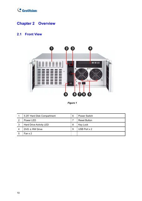
Chapter 2 Overview2.1 Front View1 2 3 498765Figure 11 5.25” Hard Disk Compartment 6 Power Switch2 Power LED 7 Reset Button3 Hard Drive Activity LED 8 Key Lock4 DVD ± RW Drive 9 USB Port x 25 Fan x 210
2Overview2.2 Rear ViewFigure 21 RS-485 ± for PTZ Control 10 USB Port x 42 RJ-11 Port 11 VGA Monitor Port3 D-Type Audio Port x 2 12 LPT Parallel Printer Port4 BNC Connector x 16 13 DB-9 Serial Input5 RCA TV Output 14 PS/2 Mouse Input6 Audio Microphone In Port 15 PS/2 Keyboard Input7 Audio Line In Port 16 AC Power Switch8 Audio Line Out Port 17 AC Power Input (Full Range)9 Ethernet Port x 211
- Page 1 and 2: GV-DVR System V2User’s Manual
- Page 3: User’s Manual for GV-DVR System V
- Page 7: Safety InstructionsObserve these sa
- Page 11: 1Introduction1.3 OptionsOptional de
- Page 15 and 16: 3Getting Started3.2 Turning on the
- Page 17 and 18: 3Getting Started5. Configure a stat
- Page 19 and 20: 3Getting StartedTo modify the defau
- Page 21 and 22: 3Getting Started3.5 Recovery DVDIf
- Page 23 and 24: 3Getting Started3.6 Updating GV-DVR
- Page 25 and 26: 4DVR Health Analysis2. Select Backu
- Page 27 and 28: 4DVR Health Analysis4.3 Information
- Page 29 and 30: 4DVR Health Analysis4.4 Health Anal
- Page 31 and 32: 5TroubleshootingThe Main System can
- Page 33 and 34: 5TroubleshootingF. Select Use the f
- Page 35 and 36: 5TroubleshootingC. Click the Tools
- Page 37 and 38: SpecificationsSpecificationsSystemM
- Page 39 and 40: SpecificationsRemote Client Softwar
- Page 41 and 42: Warranty PolicyWarranty PolicyWarra
- Page 43: Warranty PolicyWhen you call or e-m
- Page 46: Bar Code:Shipment Date:GeoVision, I
Chapter 2 Overview2.1 Front View1 2 3 498765Figure 11 5.25” Hard Disk Compartment 6 Power Switch2 Power LED 7 Reset Button3 Hard Drive Activity LED 8 Key Lock4 DVD ± RW Drive 9 USB Port x 25 Fan x 210


