

Jian-Jiun Ding, Wei-Lun Chao, Jiun-De Huang, and Cheng-Jin Kuo
Jian-Jiun Ding, Wei-Lun Chao, Jiun-De Huang, and Cheng-Jin Kuo
Jian-Jiun Ding, Wei-Lun Chao, Jiun-De Huang, and Cheng-Jin Kuo
- No tags were found...

Create successful ePaper yourself
Turn your PDF publications into a flip-book with our unique Google optimized e-Paper software.
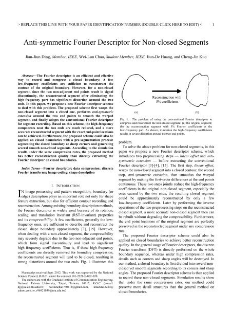
REPLACE THIS LINE WITH YOUR PAPER IDENTIFICATION NUMBER (DOUBLE-CLICK HERE TO EDIT) < 22-DcontouryShapesignaturex1-Dsignature(a)(b)DFTThe contributions of this paper are summarized as follows:• A new Fourier descriptor scheme is presented to compress<strong>and</strong> reconstruct the non-closed segments, which maintainsthe compressibility <strong>and</strong> exactly preserves the end pointlocations.• The proposed Fourier descriptor scheme could also be usedon closed boundaries with a pre-segmentation process. Thismethod outperforms the general method under the samecompression rates for boundary reconstruction.• Extensive simulations on several Chinese characters <strong>and</strong> thest<strong>and</strong>ard MPEG-7 CE-shape-1 database [8] are conducted.This paper is organized as follows: In Section II, we brieflyreview the concept of Fourier descriptors <strong>and</strong> previous work onnon-closed segments. In Section III, the proposed Fourierdescriptor scheme for non-closed segments is presented. Theextension of the proposed scheme towards closed boundaries isdescribed in Section IV. In Section V, several simulations areperformed to demonstrate the effectiveness of our method onboth closed <strong>and</strong> non-closed contours. Finally, in Section VI, weconclude this paper.II. REVIEW OF FOURIER DESCRIPTORSFrequencyCoefficientsA. The Basic Concept of Fourier <strong>De</strong>scriptorsAccording to existing literatures, Fourier descriptors havetwo main purposes in practice: One is to extract a compactshape descriptor for matching <strong>and</strong> retrieval [2], [4]-[5], [7]-[8],[10], [13]-[14], [18]; the other is to efficiently record <strong>and</strong>compress the boundaries [4][11][16][19], which is the majorconcern of this paper.The Fourier descriptor algorithm consists of two stages:shape signature <strong>and</strong> discrete Fourier transform (DFT). Thefirst stage maps the 2-D boundary into a 1-D sequence, calledthe shape signature [18]; the second stage then applies the DFTon this 1-D signature, resulting in a set of DFT frequencycoefficients to represent the boundary. To describe <strong>and</strong> recordnPreservedcoefficientsFig. 2. The general procedure of Fourier descriptors: (a) the flowchart with 2stages: shape signature <strong>and</strong> the DFT; (b) an example to illustrate the input<strong>and</strong> output of the two stages. For efficient recording <strong>and</strong> description, only thelow-frequency coefficients are preserved.kthe boundary efficiently, only the low-frequency coefficientsare kept. Fig. 2 shows the procedure of Fourier descriptors.In general, the second stage is seen as a fixed operation, soprevious work of Fourier descriptors primarily focuses on howto design the shape signatures process. For example, Zahn et al.[19] proposed the cumulative angular function along theboundary; Granlund [4] used the complex coordinate, denotedas the conventional Fourier descriptor in this paper. In [20][21]Zhang et al. gave comparative studies among several existingshape signatures on the matching performance. An importantcharacteristic of shape signatures is the reversibility: If theshape signature is not reversible from the 1-D sequence to the2-D boundary, it is not available for boundary reconstruction.There is also some work aiming to explore the RST-invariantproperties <strong>and</strong> to design the matching metric for accurate imageretrieval [1], [13]. And in [22], Zhang et al. presented a specialFourier descriptor algorithm that performs the 2-D Fouriertransform on the whole image rather than performs the 1-DFourier transform on the boundary sequence.B. Fourier <strong>De</strong>scriptors for Non-closed SegmentsThe Fourier descriptors mentioned above are mainly used forclosed boundaries. However, for non-closed segments, whichfrequently occur in character recognition <strong>and</strong> edge recording,their performances may degrade due to the non-adjacent endpoints. That is, the non-adjacent end points lead to signaldiscontinuity at the two ends of the 1-D signature, resulting insignificant high-frequency coefficients that cannot be directlyeliminated for contour recording.To solve this problem, the shape signature process should bedesigned to produce a signature with similar end point values.In previous work, Uesaka [16] computed the sequential pointdifference along a contour as the shape signature. His methoddoes reduce the high-frequency components in the shapesignature <strong>and</strong> preserve the exact end point locations, but theequal-length sampling process is not suitable for digital images.In [11], Nijim first extended the non-closed segment at the twoends, <strong>and</strong> then applied the Fourier descriptor. He claimed thatafter compression, the distortion would only appear at theextended part, <strong>and</strong> the original end points could be preserved;the extended length, however, is remained undefined. In [17],Weyl<strong>and</strong> et al. proposed the generalized Fourier descriptor bymodifying the cumulative angular function, whereas it has beenmentioned in [16], [21] that this function has slow convergencespeed <strong>and</strong> is not suitable for boundary compression.Another method to solve the non-closed segment problem isto perform the discrete cosine transform (DCT) rather than theDFT on the shape signature. Namely, the shape signature is firstextended into the even-symmetric form, which indeed has sameend point values; the DFT is then applied to get the frequencycoefficients for contour recording. Although this method isefficient <strong>and</strong> could alleviate the distortions after compression,the end point locations are not guaranteed to be preserved.III. THE PROPOSED FOURIER DESCRIPTOR SCHEMEIn this paper, our main concerns are boundary compression<strong>and</strong> reconstruction rather than the matching <strong>and</strong> retrieval
REPLACE THIS LINE WITH YOUR PAPER IDENTIFICATION NUMBER (DOUBLE-CLICK HERE TO EDIT) < 3yProposed Fourier descriptor schemeyxComplexcoordinateLinearoffsetAnti-symmetricextensionCompression +ReconstructionFig. 3. The flowchart of the proposed Fourier descriptor scheme. Given a non-closed segment, the complex-coordinate mapping first records thesegment as a 1-D complex sequence. Then, the proposed linear-offset <strong>and</strong> anti-symmetric extension (illustrated by the blue dash boxes) areperformed to close <strong>and</strong> smooth the segment. Finally, the DFT is executed to achieve the frequency coefficients for boundary compression. The maingoal of our scheme is to approximately reconstruct the non-closed segment with the exact endpoint locations.DFTxpurposes, meaning that the shape signature process should bereversible. Instead of designing a new reversible shapesignature with similar end point values for non-closed segments,we adopt the complex-coordinate mapping [4] (a reversiblesignature) <strong>and</strong> present two modification steps — linear offset<strong>and</strong> anti-symmetric extension — to close <strong>and</strong> smooth theoriginal non-closed segment. With these modifications, thefinal 1-D sequence fed into the DFT would have much smallerhigh- frequency components (as in Fig. 5) <strong>and</strong> could beapproximately reconstructed by the low-frequency coefficients.In addition, no matter how many DFT coefficients are remainedfor boundary compression, our scheme is proved to keep theexact end point locations after reconstruction. Fig. 3 depicts theflowchart of the proposed Fourier descriptor scheme, <strong>and</strong> in thefollowing sub- sections, we describe each step in order. Notethat the complex- coordinate step could be placed afteranti-symmetric extension without causing any difference to theresulting descriptor.y 0yx 0sn00 0s x jys N 1The original segmentrepresented bycomplex coordinatesxyx(a) Linear offsetyssW nWEnxA. The Complex-coordinate MappingGiven an N-point boundary xn, ynn 0,1,......, N 1 ,the complex-coordinate mapping [4] represents each contourpoint as a complex number <strong>and</strong> generates a complex sequences(n) as follows:sn ( ) xn ( ) jyn ( ), for k0,1,......, N 1 (1)where the x-axis is treated as the real part; the y-axis, imaginarypart. If the boundary is not closed, the sequence s(n) isobviously discontinuous at the two ends <strong>and</strong> its DFT willcontain large high-frequency coefficients.B. Linear OffsetTo reduce the high-frequency components derived from thenon-adjacent end points, an intuitive idea is to warp the originalsegment into a closed one. In this paper, we present a linearoffset algorithm to achieve this goal: A contour point (x n , y n ) onthe original segment is linearly shifted to (x n ’, y n ’) based on thefollowing rule:x' n xn x0 ( xN1x0) n/( N1) ,y' n yn y0 ( yN1 y0) n/( N1) ,for n 0,1,......, N 1.Note that x 0 ’ = x N1 ’ = 0 <strong>and</strong> y 0 ’ = y N1 ’ = 0. This rule shifts eachcontour point according to its index <strong>and</strong> the difference betweenthe end points. The warped segment then becomes a closed one(2)named s W (n), which is shown as in Fig. 4(a):s ( n) x ', y ' n 0,1,......, N 1 . (3)W n n(b) Anti-symmetric extensionFig. 4. The illustration of performing (a) linear-offset (resulting in a sharpangle at the origin) <strong>and</strong> (b) anti-symmetric extension on a non-closedsegment. As shown, the output segment after these two steps become aclosed one <strong>and</strong> has continuous first-order differences at the two end points.The linear offset algorithm is reversible from (x n ’, y n ’) backto (x n , y n ) by keeping the two end point locations, ensuring itsavailability for boundary reconstruction. And as illustrated inFig.5, the resulting closed segment has smaller high-frequencycomponents than the original non-closed one; the reconstructedsegment from s W (n) with 2.5% compression rate could preservethe non-closed shape. The compression rate <strong>and</strong> reconstructionprocess are described later in Sections III-D <strong>and</strong> III-E.However, even after linear offset, the linked two ends maylead to a sharp angle on the contour, therefore still containinghigh-frequency components. In addition, the end pointlocations are not guaranteed to be preserved afterreconstruction.C. Anti-symmetric ExtensionTo smooth the sharp angle generated by the linear offset, wefurther propose the anti-symmetric extension scheme by adding
REPLACE THIS LINE WITH YOUR PAPER IDENTIFICATION NUMBER (DOUBLE-CLICK HERE TO EDIT) < 4snsW ns nWEOriginalsegmentLinear offsetAnti-symmetricextensionDFTresponseReconstructedsegment(2.5% compression rate)Smaller highfrequencycoefficientsFig. 5. Illustrations of the segment shapes (Row 1), DFT responses (Row 2), <strong>and</strong> reconstruction shapes with 2.5% coefficients (Row 3) afterapplying linear offset (Column 2) <strong>and</strong> anti-symmetric extension (Column 3). The original segment is 321-point long <strong>and</strong> its DFT has 321coefficients. The anti-symmetric extended segment is 640-point long then with 640 coefficients; however, only part of them are essential. Forclearness, in Row 2 only 20% of the coefficients around the zero frequency are shown; the magnitude responses are plotted in the log scale. Row3 shows the reconstructed segments with only 8 complex values (about 2.5% of the original 321 coefficients) based on each input signatures. Thered boxes in Row 2 mark the coefficients preserved, <strong>and</strong> for s W(n) <strong>and</strong> s W+E(n), 2 of the 8 remained complex values are the end point locations.an anti-symmetric segment of s W (n) behind s W (n), as illustratedin Fig. 4(b). The new (2N-2)-point segment s W+E (n), withWarping <strong>and</strong> Extension, is defined as follows:sW( n) , for n 0,1,..., N 1sWE( n) , (4) sW(2N 2 n) , for n N,...,2N 3which is closed <strong>and</strong> has continuous first-order <strong>and</strong> zero secondorderdifferences at the two end points (hence much smoother).Note that adding the anti-symmetric segment in s W+E (n) doesnot increase the amount of coefficients to preserve, since theDFT frequency response of an anti-symmetric signal is alsoanti- symmetric. Therefore, only half of the Fourier coefficientsof s W+E (n) are required to keep for lossless reconstruction.As illustrated in Fig. 5, s W+E (n) has even smaller highfrequencycomponents than s W (n); besides, the reconstructedsegment from s W+E (n) with 2.5% compression rate has betterquality — with the exact end point locations — than that froms(n) <strong>and</strong> s W (n).D. DFT <strong>and</strong> Boundary CompressionAfter linear offset <strong>and</strong> anti-symmetric extension, the resultingsequence s W+E (n) is then fed into the DFT to get the frequencycoefficients S(k):2N31j2 nk/(2N2)Sk ( ) sWE( ke ) . (5)2N 2k 0Since s W+E (n) is of zero mean <strong>and</strong> S(k) is anti-symmetric withS(k) = -S(2N-2-k), both S(0) <strong>and</strong> S(N-1) are 0. Thus to achievelossless reconstruction, only S(k) at k = 1, 2, ……, N-2 arerequired.For boundary compression, the first P coefficients (S(k) at k= 1, 2, ……, P; 0≦ P ≦ N-2) are remained, <strong>and</strong> totally P+2complex values, including the two end point locations, arerecorded for reconstruction. The compression rate (CR) utilizedin this paper is defined as:# recorded complex valuesCR 100%. (6)# original segment lengthFor the proposed scheme, CR is computed as:P 2CR 100%.(7)NE. Boundary Reconstruction from the Proposed SchemeThe reconstruction process from the preserved P coefficients<strong>and</strong> the two end point locations is listed as follows:• (Step1): Regenerate the (2N-2)-long frequency responseS*(k) from the P preserved coefficients by zero padding <strong>and</strong>anti-symmetric extension.• (Step 2): Perform the inverse DFT to get s W+E *(n).• (Step 3): Eliminate the anti-symmetric part in s W+E *(n) to gets W *(n) <strong>and</strong> perform the inverse operations of (2) to achievethe reconstructed segment s*(n).In Fig. 6, both the boundary compression <strong>and</strong> reconstructionprocesses are summarized.F. Proof of the Exact End Point Preserving PropertyIn this subsection, we give the proof of the exact end point
REPLACE THIS LINE WITH YOUR PAPER IDENTIFICATION NUMBER (DOUBLE-CLICK HERE TO EDIT) < 5yProposed Fourierdescriptor schemeSnAnti-symmetric2N 3kConventionalFourierdescriptorx SNS 0 1 0BoundarycompressionBoundaryPre-segmentationSeg-FDReconstructionwith CR = 2.5%ypreserving property of the proposed Fourier descriptor scheme:No matter how many DFT coefficients are remained, the endpoints of the reconstructed segment will coincide with those ofthe original segment. This proof can be achieved by checkings W *(0) <strong>and</strong> s W *(N-1), which are the end point locations of thereconstructed segment of s W (n). As mentioned in (2), the twoend values of s W (n) are 0; then if s W *(0) <strong>and</strong> s W *(N-1) are also 0,the reconstructed non-closed segment s*(n) after the inverseoperations of (2) will have the same end points as what s(n) has.The formulas of s W *(0) <strong>and</strong> s W *(N-1) are presented as follows:P2N3j20 k/(2N2) j20 k/(2N2) k1 k2N2PP2N3s *(0) S( k) e S( k)eWk1 k2N2PPk 1Sk ( ) Sk ( ) Sk ( ) S(2N2 k) 0,(8)P2N3j2 ( N1) k/(2N2) j2 ( N1) k/(2N2)k1 k2N2PP2N3jkSke( ) jkSke ( )k1 k2N2PPSk ( ) S(2N 2jkk) e0k 1s *( N 1) S( k) e S( k)eWxReconstruction(Step 2 & 3)S*n P coefficients +2 end point locationsReconstruction(Step 1)Anti-symmetric2N 3kZero paddingFig. 6. Illustrations of both the boundary compression <strong>and</strong> the reconstructionprocesses: After applying the proposed scheme, P of the coefficients <strong>and</strong> thetwo end point locations are remained for boundary recording. To reconstructthe non-closed segment, we first regenerate the (2N-2)-long coefficientsequence (Step 1) <strong>and</strong> then perform Steps 2 & 3 in Section III-D to achieve it.where the anti-symmetric property of S(k) is considered, whichis derived from the proposed anti-symmetric extension; withoutanti-symmetric extension, the end point preserving property isnot guaranteed after boundary compression. Note that both (8)<strong>and</strong> (9) are held under arbitrary P (0≦ P ≦ N-2).(9)ProposedFourierdescriptorFig. 7. The flowchart <strong>and</strong> illustration of the proposed Seg-FD framework forclosed boundary: The top row shows the reconstruction result using theconventional Fourier descriptor [4] with 2.5% compression rate. The bottompart shows the result of Seg-FD (the dash box). As shown, the proposedSeg-FD framework could lead to better reconstruction quality, especiallyaround the corners.IV. THE PROPOSED METHOD FOR CLOSED BOUNDARIESThe proposed Fourier descriptor scheme could directly beapplied on closed boundaries; the resulting Fourier descriptors<strong>and</strong> reconstructed boundaries are similar to the ones achievedby applying the convectional Fourier descriptor [3]-[4], [15] —since the linear offset step mentioned in Section III-B does notchange the shapes of the originally closed boundaries.Generally, Fourier descriptors are very efficient <strong>and</strong>effective for recording closed boundaries; under highcompression rates, however, detailed structures of the originalboundaries such as corners <strong>and</strong> sharp angles still cannot bemaintained. To alleviate this problem, we further propose aframework named Seg-FD:Seg-FD performs boundary Segmentation at first togenerate several non-closed yet smooth segments, <strong>and</strong> thenapplies the proposed Fourier <strong>De</strong>scriptor scheme to record thesesegments. The flowchart of Seg-FD is depicted in Fig. 7.A. Boundary Pre-segmentationIn order to create smooth non-closed segments, sharp anglesor corners on the closed boundary should be detected first; theclosed boundary is then divided at these positions into severalnon-closed segments containing no corners inside. There havebeen many corner detection algorithms in existing literatures,like the Harris corner detector [6], SIFT [9], <strong>and</strong> the machinelearning approach in [12]. These methods, nevertheless, aredesigned mainly for corner detection in regular images, <strong>and</strong>either with high computational complexity or requiring alearning step. For our cases on binary contour images <strong>and</strong> forefficient detection, a simple algorithm through checking theinner products along contours (shown in Fig. 8) is utilized.Given an N-point boundary {(x n , y n )| n = 0, 1, …, N1}thiscorner detection algorithm goes through each point (x n , y n ) in
REPLACE THIS LINE WITH YOUR PAPER IDENTIFICATION NUMBER (DOUBLE-CLICK HERE TO EDIT) < 6xx , ynnqnx, ynq, ynqnq(a)ContourFig. 8. The corner detection algorithm used in our paper: (a) for each pointon the contour, two neighboring points (with q = 4) are selected; (b) The twovectors generated by (10) are used to compute the normalized inner product.Reconstructionwith CR = 2.5%Seg-FDwith DCTFig. 9. The illustration of applying the complex coordinates [4] (for shapesignatures) <strong>and</strong> the DCT in Seg-FD: The compression rate is 2.5%. Withoutthe end point preserving property, the reconstructed segment is broken at thecorners.turn <strong>and</strong> computes the normalized inner product NIP(n) definedas follows:v1v2NIP( n) ,v1 v2Twith v1 xnqxn, ynqyn, (10)Tv2 xnqxn,ynqynwhere q is an index offset (e.g. q = 4) for defining v 1 <strong>and</strong> v 2 . IfNIP(n) is larger than a predefined threshold, (x n , y n ) is markedas a corner on the contour; the detected corners are then sortedaccording to their NIPs in the descending order, <strong>and</strong> the top Lcorners are selected for boundary segmentation. To prevent tooclose corners, a lower bound of corner intervals is also defined.B. Boundary CompressionAfter segmenting the closed boundary into L non-closedsegments, the proposed Fourier descriptor scheme is applied onthese segments: each segment is recorded by a number ofcoefficients proportional to its length. Although one segmenthas two end points, the total number of end points to keep is justL since two segments share a common end point (corner).For boundary compression at CR = K/N×100%, the totalnumber of recorded DFT coefficients P <strong>and</strong> corners L aresummed to be K, leading to a balancing problem on P <strong>and</strong> L. Inour implementation, a balance parameter BP (0 ≦ BP ≦ 1) isset to restrict the number of corners; that is, L ≦ BP×K,meaning that at most BPK corners are selected (based ontheir NIP values) for boundary segmentation.C. Boundary ReconstructionBoundary reconstruction is achieved by first rebuilding the Lnon-closed segments <strong>and</strong> then linking them together. Thanks tothe end point preserving property, the reconstructed non-closedsegments exactly keep the end point locations, guaranteeingv 1(b)v 2(a)1 2 3 4 5 67 8 9 10 11 12(b)Fig. 10. Samples of the two data sets used in our simulations: (a) the MPEG-7 Core Experiment CE-shape-1 Part B database (each column shows twosamples of the same class); (b) the Chinese character data set collected byourselves (the number below each sample shows its frequency rank).that the reconstructed whole boundary is continuous, with norifts at the corners. Except for the proposed Fourier descriptorscheme <strong>and</strong> Uesaka’s method [16], other Fourier descriptorsdo not have this property <strong>and</strong> cannot be applied in the Seg-FDframework for non-closed segment recording. Fig. 9 shows thecase of using the DCT (with the complex-coordinate mapping)in Seg-FD: The reconstruct boundary is broken at the corners.V. SIMULATION RESULTSIn this section, several experiments of boundary compression(reconstruction) are conducted to demonstrate the effectivenessof the proposed methods. For non-closed segments, wecompare the proposed Fourier descriptor with the conventionalFourier descriptor [4], Uesaka’s method [16], Nijim’s method[11], <strong>and</strong> the DCT method that uses the complex coordinate asthe shape signature; other shape signatures introduced inSection II-A or surveyed in [20], [21] are not included becausethey are not reversible. And for closed boundaries, our Seg-FDframework is compared with the conventional Fourierdescriptor [4].A. Data Sets <strong>and</strong> Evaluation CriteriaTwo data sets are utilized in the experiments: One is theMPEG-7 Core Experiment CE-shape-1 Part B [8] (MPEG-7database in short), which contains 1400 shape contour imagesfrom 70 object classes, each class with 20 images; the other is aChinese character data set with the most frequently-used 50characters, collected by ourselves. Fig. 10 shows some samplesof these two data sets. Note that in the MPEG-7 database, eachimage may contain more than one closed contours, <strong>and</strong> only thelargest one is selected to represent each image.To evaluate the reconstruction performance, the normalizedL1 <strong>and</strong> L2 distances (normalized by the contour length)between the original contour s(n) <strong>and</strong> reconstructed contourss*(n) are computed as the reconstruction errors:
REPLACE THIS LINE WITH YOUR PAPER IDENTIFICATION NUMBER (DOUBLE-CLICK HERE TO EDIT) < 975Mean normalized L1 distance654321Conventional [4]Seg-FD + Uesaka [16]Seg-FD + Proposed schemeMean normalized L1 distance4321Conventional [4]Seg-FD + Uesaka [16]Seg-FD + Proposed scheme02 4 6 8 10 12 14 16Compression rate CR (%)(a)702 4 6 8 10 12 14 16Compression rate CR (%)(a)5Mean normalized L2 distance654321Conventional [4]Seg-FD + Uesaka [16]Seg-FD + Proposed schemeMean normalized L2 distance4321Conventional [4]Seg-FD + Uesaka [16]Seg-FD + Proposed scheme02 4 6 8 10 12 14 16Compression rate CR (%)(b)Fig. 15. The average reconstruction errors of closed boundaries computedon the MPEG-7 database under varied compression rates: (a) the averagenormalized L1 error; (b) the average normalized L2 error.02 4 6 8 10 12 14 16Compression rate CR (%)(b)Fig. 16. The average reconstruction errors of closed boundaries computedon 50 Chinese characters under varied compression rates: (a) the averagenormalized L1 error; (b) the average normalized L2 error.method, <strong>and</strong> Seg-FD + the proposed Fourier descriptorscheme — on both the MPEG-7 database <strong>and</strong> the 50 Chinesecharacters. Other Fourier descriptors included in thenon-closed segment case are not considered in Seg-FD becauseof the lack of the end point preserving property. Since eachChinese character may contains several disconnected parts withouter or even inner contours (as illustrated in Fig. 14), Seg-FD<strong>and</strong> boundary compression are performed on each contourseparately; the reconstruction error, nevertheless, is computedaccording to the whole character.’As described in Section IV-B, a balance parameter BP isrequired to set in the proposed Seg-FD framework to allot theremained K complex values into P DFT coefficient <strong>and</strong> Lcorners (P + K = L). In our implementation, we go through 10possible BPs (from 0.1 to 1 with a uniform 0.1 interval) <strong>and</strong>select the one that results in the lowest reconstruction error foreach image. The case Seg-FD with BP = 0 is not consideredsince it is the conventional Fourier descriptor. The compressionrate CR defined for Seg-FD is:K PLCR 100% 100%. (14)N NThe average reconstruction errors computed on the MPEG-7database (all the 1400 images are included) are shown in Fig.15 where Seg-FD + the proposed scheme outperforms the othertwo methods, especially Seg-FD + Uesaka’s method. This factpresents the advantage of applying the proposed scheme onrecording non-closed segments against Uesaka’s method. Theexperimental results also demonstrate the usage of Seg-FD(with the proposed Fourier descriptor scheme) for closedboundary compression. Fig. 18 presents several examples ofthe reconstructed closed boundaries at CR = 0.3 <strong>and</strong> 0.7.In Fig. 16, the reconstruction errors computed on the 50Chinese characters are present where Seg-FD + the proposedscheme still outperforms the other two methods, demonstratingits effectiveness on various shape types. Fig. 19 also presents
REPLACE THIS LINE WITH YOUR PAPER IDENTIFICATION NUMBER (DOUBLE-CLICK HERE TO EDIT) < 10Uesaka’s methodProposed schemewith the original segments.This performance difference mainly results from thedifferent usages of subtraction operations. In Uesaka’s method,the reconstructed location of point n is based on thereconstructed location of n-1, according to (13). This processwould lead to error propagation under high compression rates.The proposed scheme does not compute any subtractionbetween two points, except the point difference of the two ends,<strong>and</strong> therefore suffers no error propagation problem.Uesaka’s method(a)Proposed scheme(b)Fig. 17. The reconstruction results of Uesaka’s method <strong>and</strong> the proposedscheme on the non-closed segments used in Fig. 13 at CR = 3%. The originalsegment is plotted in gray color. As presented, Uesaka’s method has largerreconstruction error.several reconstruction examples to illustrate the performance ofSeg-FD on Chinese character compression. From the examplesin Fig. 18 <strong>and</strong> Fig. 19, we found that when the originalboundary is with many corners or sharp angles, the advantageof Seg-FD is much conspicuous. Even Seg-FD +Uesaka’smethod could result in a smaller reconstruction error than theconventional Fourier descriptor under this condition.D. DiscussionsAmong the Fourier descriptor algorithms presented in thispaper, only two of them could exactly preserve the end pointlocations of non-closed segments after boundary compression:One is the proposed scheme; the other is Uesaka’s method [16].When analyzing these two methods, we found a common trickused in the shape signature design — the subtraction operation.In (2), the proposed scheme subtracts a specific offset fromeach point based on the corresponding point index; theresulting closed segment, with the two ends located at theorigin, enables the anti-symmetric extension <strong>and</strong> indirectlyresults in the end point preserving property. In (13), Uesaka’smethod computes the point difference along the contour as thesignature, also leading to the end point preserving property asproved in [16].From the experimental results, there is, however, an obviousperformance gap between these two methods; that is, thereconstruction error of the proposed scheme is three to fourtimes smaller than the one of Uesaka’s method, though thereconstructed shape based on Uesaka’s method looks plausible.To illustrate where the comparatively high error comes from,we plot each original segment used in Fig. 13 (in gray color)<strong>and</strong> the corresponding reconstructed result together inside onefigure. As presented in Fig. 17, the reconstruction results ofUesaka’s method clearly deviate from the original segments; oncontrary, the results of the proposed scheme nearly overlapVI. CONCLUSIONThis paper aims at high quality boundary compression onboth non-closed segments <strong>and</strong> closed boundaries via theFourier descriptor. To deal with the high-frequencycoefficients caused by the non-adjacent end points ofnon-closed segments, a new Fourier descriptor scheme isproposed. The proposed scheme introduces two preprocessingsteps — linear offset <strong>and</strong> anti-symmetric extension — todrastically reduce the high-frequency components around thetwo end points before applying the conventional Fourierdescriptor. Based on this scheme, the compressibility of Fourierdescriptors on closed boundaries can be maintained even onnon-closed segments. Furthermore, the end point locations areexactly preserved after reconstruction under any compressionrate. The proposed Fourier descriptor scheme could also beapplied on closed boundaries by first segmenting a closedboundary into several non-closed yet smooth segments, whichis called the Seg-FD framework in this paper.According to the simulation results on the MPEG-7 shapedatabase <strong>and</strong> several Chinese characters, the proposed Fourierdescriptor scheme <strong>and</strong> the proposed Seg-FD framework dooutperform other Fourier descriptor algorithms.REFERENCES[1] I. Bartolini, P. Ciaccia, <strong>and</strong> M. Patella, “WARP: Accurate retrieval ofshapes using phase of Fourier descriptors <strong>and</strong> time warping distance,”IEEE Trans. Pattern Analysis <strong>and</strong> Machine Intelligence, vol. 27, no. 1, pp.142-147, 2005.[2] A. Folkers <strong>and</strong> H. Samet, “Content-based image retrieval using Fourierdescriptors on a logo database,” Proc. ICPR, pp. 521-524, 2002.[3] R. C. Gonzalez <strong>and</strong> R. E. Woods, Digital Image Processing, 3 rd Ed.,Prentice Hall, New Jersey, pp. 815-822, 2008.[4] G. H. Granlund, “Fourier preprocessing for h<strong>and</strong> print characterrecognition,” IEEE Trans. Computers, vol. 21, iss. 2, pp. 195-201, 1972.[5] P. R. G. Harding <strong>and</strong> T. J. Ellis, “Recognizing h<strong>and</strong> gesture using Fourierdescriptors,” Proc. ICPR, pp. 286-289, 2004.[6] C. Harris <strong>and</strong> M. Stephens, “A combined corner <strong>and</strong> edge detector,” Proc.Alvey Vision Conference, pp. 147-151, 1988.[7] I. Kunttu <strong>and</strong> L. Lepisto, “Shape-based retrieval of industrial surfacedefects using angular radius Fourier descriptor,” IET Image Processing,vol. 1, no. 2, pp. 231-236, 2007.[8] L. J. Latecki, R. Lakamper, <strong>and</strong> U. Eckhardt, “Shape descriptors fornon-rigid shapes with a single closed contour,” Proc. IEEE Conf. CVPR,pp. 424-429, 2000.[9] D. G. Lowe, “Distinctive image features from scale-invariant keypoints,”Int. Journal of Computer Vision, vol. 60, no. 2, pp. 91-110, 2004.
REPLACE THIS LINE WITH YOUR PAPER IDENTIFICATION NUMBER (DOUBLE-CLICK HERE TO EDIT) < 11[10] F. Marques, B. Llorens, <strong>and</strong> A. Gasull, “Prediction of image partitionsusing Fourier descriptors: application to segmentation-based codingschemes,” IEEE Trans. Image Processing, vol. 7, iss. 4, pp. 529-542,1998.[11] A. Nijim, Smart Dust: Distributed Behavior-Based Mobile Agents forThinning Segmentation <strong>and</strong> Feature Extraction of H<strong>and</strong>-Written Arabic<strong>and</strong> Chinese words, M.S. thesis, Concordia University, Montreal, Quebec,Canada, 2004.[12] E. Rosten <strong>and</strong> T. Drummond, “Machine learning for high-speed cornerdetection,” Proc. ECCV, pp. 430-443, 2006.[13] Y. Rui, A. C. She, <strong>and</strong> T. S. <strong>Huang</strong>, “Modified Fourier descriptors forshape representation — A practical approach,” Proc. Int. WorkshopImage Databases <strong>and</strong> Multimedia Search, 1996.[14] V. Solachidis, N. Nikolaidis, <strong>and</strong> I. Pitas, “Watermarking polygonal linesusing Fourier descriptors,” Proc. IEEE ICASSP, pp. 1955-1958, 2000.[15] S. Theodoridis <strong>and</strong> K. Koutroumbas, Pattern Recognition, 3 rd Ed.,Academic Press, San Diego, 2006, pp. 353-362.[16] Y. Uesaka, “A new Fourier descriptor applicable to open curves,” Trans.IEICE, vol. 67, no. 8, pp. 166-173, 1984.[17] N. B. J. Weyl<strong>and</strong> <strong>and</strong> R. Prasad, “Characterization of line drawings usinggeneralized Fourier descriptors,” Electronics Letters, vol. 26, no. 21, pp.1794-1795, 1990.[18] W. T. Wong, F. Y. Shih, <strong>and</strong> J. Liu, “Shape-based image retrieval usingsupport vector machines, Fourier descriptors <strong>and</strong> self-organizing maps,”Information Sciences, vol. 177, pp. 1878-1891, 2007.[19] C. T. Zahn <strong>and</strong> R. Z. Roskies, “Fourier descriptors for plane closedcurves,” IEEE Trans. Computers, vol. 21, no. 3, pp. 269-281, 1972.[20] D. S. Zhang <strong>and</strong> G. Lu, “Content-based shape retrieval using differentshape descriptors: a comparative study,” Proc. of IEEE ICME, pp.317–320, 2001.[21] D. S. Zhang <strong>and</strong> G. J. Lu, “A comparative study of Fourier descriptors forshape representation <strong>and</strong> retrieval,” Proc. ACCV, pp. 646-651, 2002.[22] D. S. Zhang <strong>and</strong> G. J. Lu, “Shape-based image retrieval using genericFourier descriptor,” Signal Processing: Image Communication, vol. 17,pp. 825-848, 2002.
REPLACE THIS LINE WITH YOUR PAPER IDENTIFICATION NUMBER (DOUBLE-CLICK HERE TO EDIT) < 12OriginalOriginalCR 3% 7%L1 = 2.36 L1 = 0.57CR 5% 8%L1 = 2.24 L1 = 0.79Conventional [4]Conventional [4]Seg-FD +Uesaka’s [16]L1 = 3.27 L1 = 1.36Seg-FD +Uesaka’s [16]L1 = 1.98 L1 = 1.41L1 = 0.98 L1 = 0.53L1 = 0.57 L1 = 0.22Seg-FD +Proposed schemeSeg-FD +Proposed scheme(a)(a)OriginalOriginalCR 3% 7%L1 = 3.94 L1 = 1.20CR 5% 8%Conventional [4]L1 = 2.25 L1 = 0.96Conventional [4]L1 = 1.32 L1 = 1.03Seg-FD +Uesaka’s [16]Seg-FD +Proposed schemeL1 = 1.27 L1 = 0.94L1 = 1.26 L1 = 0.60Seg-FD +Uesaka’s [16]Seg-FD +Proposed schemeL1 = 1.30 L1 = 0.83(b)Fig. 18. Samples of the reconstructed closed boundaries (from the MPEG-7database) at CR = 3% <strong>and</strong> 7%. The normalized L1 distance is also presented.As shown, Seg-FD + the proposed Fourier descriptor scheme outperforms theother methods on both the reconstruction quality <strong>and</strong> the L1 error.(b)Fig. 19. Samples of the reconstructed Chinese characters at CR = 5% <strong>and</strong> 8%.The normalized L1 distance is also presented. As shown, Seg-FD + theproposed Fourier descriptor scheme outperforms the other methods on boththe reconstruction quality <strong>and</strong> the L1 error.

