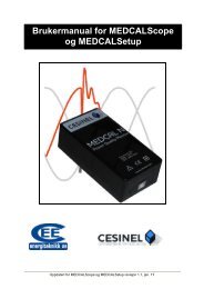
SINGLE PHASE RELAY TEST SET MOD T1000
SINGLE PHASE RELAY TEST SET MOD. T1000
SINGLE PHASE RELAY TEST SET MOD. T1000
- No tags were found...

Create successful ePaper yourself
Turn your PDF publications into a flip-book with our unique Google optimized e-Paper software.
DATE: 09/04/2008 DOC.SIE10093 REV.10<strong>SINGLE</strong> <strong>PHASE</strong> <strong>RELAY</strong> <strong>TEST</strong> <strong>SET</strong><strong>MOD</strong>. <strong>T1000</strong>
DOC. SIE10093 Rev. 10 Page 2 of 36REVISIONS SUMMARY VISAN PAGE DATE1 All 26/09/2002 Preliminary issue Lodi.2 All 04/10/02 Preliminary issue Lodi3 26 8/7/2003 Added the optional cable set paragraph Lodi4 4 1/12/2003 Modified to 1.4 kV the dielectric rigidity Lodi5 29, 30 24/8/2004 Added D/1000 option Lodi6 18 22/01/2005 Increased the AC voltage measurement ranges Lodi7 15; 17 02/02/2006 Added the range change values Lodi8 30 22/10/2006 Added the 15 Hz option and “E” option, plus Lodithe test of thermal protection and circuitbreakers.9 30 10/8/2007 Added the C model Lodi10 30 9/4/2008 Added information for the 110 V model Lodi
DOC. SIE10093 Rev. 10 Page 3 of 36APPLICABLE STANDARDS................................................................................................................................................ 41 INTRODUCTION................................................................................................................................................................ 52 CHARACTERISTICS ........................................................................................................................................................ 72.1 MAIN GENERATOR............................................................................................................................................................. 72.1.1 Main AC current ..................................................................................................................................................... 72.1.2 Main AC voltage...................................................................................................................................................... 82.1.3 Main DC voltage...................................................................................................................................................... 82.1.4 Other features of main outputs.............................................................................................................................. 92.2 AUXILIARY AC VOLTAGE.................................................................................................................................................. 92.3 AUXILIARY DC VOLTAGE................................................................................................................................................ 122.4 TIMER.............................................................................................................................................................................. 122.5 <strong>TEST</strong> CONTROL................................................................................................................................................................ 132.6 AUXILIARY CONTACT....................................................................................................................................................... 142.7 OUTPUTS MEASUREMENT ............................................................................................................................................... 152.7.1 Current and voltage .............................................................................................................................................. 152.7.2 Phase angle............................................................................................................................................................ 162.7.3 Other measurements.............................................................................................................................................. 162.8 EXTERNAL INPUTS MEASUREMENT................................................................................................................................ 172.8.1 Current measurement ........................................................................................................................................... 172.8.2 Voltage measurement............................................................................................................................................ 182.8.3 Other measurements.............................................................................................................................................. 182.9 DISPLAY........................................................................................................................................................................... 192.10 MENU SELECTIONS ....................................................................................................................................................... 192.11 OTHER CHARACTERISTICS............................................................................................................................................. 262.12 OPTIONS ........................................................................................................................................................................ 272.12.1 Power supply, code PII20093 ............................................................................................................................ 272.12.2 Connection cable kit, code ZII18093................................................................................................................ 282.12.3 Transit case, code PII17093 .............................................................................................................................. 282.12.4 “E” model: higher AC voltage outputs, code PII30093................................................................................. 282.12.5 D1000 differential relay test module, code PII40093..................................................................................... 282.12.6 15 Hz auxiliary voltage output, code PII70093............................................................................................... 292.12.7 C model, code PII50093 ..................................................................................................................................... 292.12.8 FT/100 current filter, code PII41024 ............................................................................................................... 292.12.9 SHA-1000 scanning head for <strong>T1000</strong> and T3000, code PII43102................................................................ 303 PROTECTIONS ................................................................................................................................................................ 314 LEGEND OF DRAWINGS.............................................................................................................................................. 32
DOC. SIE10093 Rev. 10 Page 4 of 36APPLICABLE STANDARDSThe test set conforms to the EEC directives regarding Electromagnetic Compatibility and LowVoltage instruments.A) Electromagnetic Compatibility:Directive no. 89/336/CEE dated may 3, 1989, modified by the directive 92/31/CEE dated may5, 1992. Applicable Standard : EN61326 + A1 + A2.EMISSION- EN 61000-3-2: Harmonic content of power supply. Acceptable limits: basic.- EN 61000-3-3: Limitation of voltage fluctuations and flicker. Acceptable limits: basic.- CISPR16 (EN 55011 class A): Limits and measurement methods of radio-electric disturbances forindustrial, medical and scientific instruments at radio-electric frequencies.Acceptable limits for conducted emission:. 0.15-0.5 MHz: 79 dB pk; 66 dB avg.. 0.5-5 MHz: 73 dB pk; 60 dB avg.. 5-30 MHz: 73 dB pk; 60 dB avg.Acceptable limits for radiated emission:. 30-230 MHz: 40 dB (30 m). 230-1000 MHz: 47 dB (30 m)IMMUNITY- EN 61000-4-2: Immunity tests for ESD. Test values: 8 kV in air; 4 kV in contact.- EN 61000-4-3; Immunity tests for radio frequency interference. Test values (f= 900 ± 5 MHz): field10 V/m, modulated AM 80%; 1 kHz- EN 61000-4-4; Immunity tests for high speed transients (burst). Test values: 2 kV peak; 5/50 ns.- EN 61000-4-5; Immunity tests for surge. Test values: 1 kV peak differential mode; 2 kV peakcommon mode; 1.2/50 us.- EN 61000-4-6: immunity to low-voltage sinusoidal waveform. Test values: 0.15-80 MHz, 10 Vrms,80% AM 1 kHz.- EN 61000-4-8: Immunity tests for low frequency magnetic fields. Test values: 30 Arms/m.- EN 61000-4-11: Immunity test for power supply drops. Test value: 1 cycle; 100% drop.B) Low Voltage Directive:- Directive n. 73/23/CEE, modified by the directive 93/68/CEE.- Applicable standard: EN 61010-1. In particular, for a pollution degree 2: dielectric rigidity 1.4 kVAC, 1 minute.- Inputs/outputs protection: IP 2X - EN60529.- Operating temperature: 0 to 50 °C; storage: -20 °C to 70 °C.- Relative humidity : 5 - 95%, without condensing.- Vibration: IEC 68-2-6 (20 m/s^2 at 10 – 150 Hz);- Shock: IEC 68-2-27 (15 g; 11 ms; half-sine).- Altitude: less than 2000 m.
DOC. SIE10093 Rev. 10 Page 5 of 361 INTRODUCTIONThe single phase relay test set mod. <strong>T1000</strong> is suited for the testing and adjustments of the followingtypes of relays.Type of relayIEEE code- Distance* 21- Synchronizing 25- Thermal 26- Over/under-voltage 27 - 59- Power, varmetric or wattmetric 32 - 92- Under current 37- Reverse phase current 46- Instantaneous overcurrent 50- Ground fault 50N- Timed overcurrent 51- Circuit breaker 52- Power factor 55- Directional overcurrent 67- Directional ground fault 67N- Automatic reclose 79- Frequency 81- Frequency rate of change 81- Motor protection 86- Differential ** 87- Directional voltage 91- Tripping relay 94- Voltage regulation- Thermal- Timers* For distance relays three <strong>T1000</strong> are necessary.** Differential starter circuitIn addition to the above, <strong>T1000</strong> can test:. Converters: V; I; f°; p.f.; W; VAr; f., both 0 to 5 and 4 to 20 mA.. Energy meters, single phase or three phase.The instrument contains three separate generators:. Main generator: it generates either AC current, AC voltage; DC voltage;. Auxiliary a.c voltage generator: it generates an independent, phase adjustable a.c voltage;. Auxiliary DC voltage generator: it generates the DC voltage that feeds the relay under test.All outputs are adjustable and metered at the meantime on the large, graphic LCD display. With themulti-purpose knob and the LCD display it is possible to enter the MENU mode, that allows to setmany functions, that make <strong>T1000</strong> a very powerful testing device, with manual and semi-automatic
DOC. SIE10093 Rev. 10 Page 6 of 36testing capabilities, and with the possibility to transfer test results to a PC via the RS232 interface.These results can be recorded, displayed and analysed by the powerful TDMS software, thatoperates with all WINDOWS versions, starting from WINDOWS 98 included.The basic <strong>T1000</strong> function is to generate current and voltages and to stop generation as the relay trips.Test results are kept in memory, and can be transferred to a PC at a later time, along with settings.The ease of operation has been the first goal of <strong>T1000</strong>: this is why the LCD is graphic, and so large.With it, the dialogue in MENU mode is made easy. Besides, all <strong>T1000</strong> outputs are continuouslymeasured, and output values are displayed, with no extra effort to the operator. Also the showwaveform feature can be of help: any doubt about strange measurements, distortion and so on canbe solved.This is also why we have added the reduced power feature. Modern relays have a very low burden.As current output is a low impedance voltage generator, adjusting low currents and/or current onlow burdens is quite difficult because one has to operate at the very beginning of the adjustmentknob. In this situation it is possible to connect resistors in series; however, one must be careful notto exceed the maximum current rating, and the wiring is more complicated. The solution to thisproblem is just to reduce the available power: this is easily performed via the multi-function knob.With less power, the maximum voltage is reduced by a factor of 4.4; the adjustment span on theknob is increased accordingly.Additional features are:. Two meters, current and voltage, with independent inputs, allow measuring <strong>T1000</strong> outputs or anyother source;. An auxiliary contact, that follows START and STOP inputs, allows simulating the circuit breaker;. A set of resistors allows easing output adjustment.The instrument is housed in a transportable aluminium box, that is provided with removable coverand handles for ease of transportation.NOTE: WINDOWS is a trademark of MICROSOFT inc.
DOC. SIE10093 Rev. 10 Page 7 of 362 CHARACTERISTICS2.1 MAIN GENERATORThe main generator has three outputs: currents, voltage AC, voltage DC. The following specificationapply to the separate usage of these outputs. It is possible to use them at the meantime, providedthat the total maximum load is not exceeded.The main generator is made of a variable transformer followed by a transformer. The variabletransformer does not reach the zero position; so, when you are adjusting the output current on a lowburden, the minimum current can be up to 5% of the range. If this is a problem, select the 60 VApower: the current is reduced to one fifth.2.1.1 Main AC current- Type of generator: voltage, high current output: the current depends upon the burden.- On all outputs is provided the capability of generating the selected current at maximum power orat reduced power. Reduced power selection eases the current adjustment for modern relays, wherethe load is negligible. Current ranges; available power; duty cycle: see the table below.1) MAXIMUM POWER 300 VARANGEA AC1004010CURRENTOUTPUTAMAXIMUMPOWERVALOADTIMEsRECOVERYTIMEmin30 300 STEADY -50 30 min 10075 600 45100 800 60 15150 3 10250 1000 1 512 300 STEADY -20 30 min 10030 600 4540 800 60 1560 3 1080 1000 1 55 400 STEADY -7.5 15 min 4510 800 60 1515 5 1020 1000 2 5
DOC. SIE10093 Rev. 10 Page 8 of 362) MAXIMUM POWER 60 VARANGEA AC1004010CURRENTOUTPUTAMAXIMUMPOWERVALOADTIMEsRECOVERYTIMEmin30 60 STEADY -38 10 min 4553 60 1070 0.75 212 60 STEADY -17 10 min 4523 60 1036 1 25 60 STEADY -6 10 min 457 60 210 1,5 2- Power selection: via menu.- Connection: four high power sockets, with safety protections, marked: 0; 10 A; 40 A; 100 A.2.1.2 Main AC voltage- The main AC voltage is isolated from the main AC current.- AC voltage range: 250 V or 54 V (reduced power; power supply 230 V), or 108 V (reduced power;power supply 115 V).- Available power and duty cycle: see table below.RANGEV ACVOLTAGEOUTPUTVLOADCONSUMPTIONVALOADTIMEminRECOVERYTIMEminREDUCEDPOWERVA250 250 500 STEADY - 60250 750 10 45 -54 (108) 54 (108) 60 STEADY - 60- Connection: two safety banana sockets.2.1.3 Main DC voltage- The main DC voltage is isolated from the main AC current, but not from the main AC voltage- DC voltage range: 300 V or 60 V (reduced power; power supply 230 V), or 120 V (reduced power;power supply 115 V).
DOC. SIE10093 Rev. 10 Page 9 of 36- Available power and duty cycle: see table below.RANGEV DCVOLTAGEOUTPUTVLOADCONSUMPTIONWLOADTIMEminRECOVERYTIMEminREDUCEDPOWERW300 300 300 STEADY - 60300 500 10 45 -60 (120) 60 (120) 60 STEADY - 60- Type of DC voltage: unregulated, via diode bridge rectifier and capacitor.- Connection: two safety banana sockets.2.1.4 Other features of main outputs- Zero crossing control. Main AC outputs are generated and stopped as the output waveform crosseszero. This implies that in mode ON+TIME the output drops to zero from 0 to one cycle after STOPis detected.- Overload alarm message. When the nominal current range is trespassed a message is displayed.- Thermal protection: by NTC. Trespassing of the maximum temperature is signalled by a message.- Output adjustment: from less than 5% to 100% of the output.- Output measurement. The used output (current, Vac, Vdc) is selected by a dedicated push-button;the selected socket is confirmed by a light.2.2 AUXILIARY AC VOLTAGE- The auxiliary AC voltage output, Vac aux, is isolated from the main AC current and voltage.- Output ranges: 65 – 130 - 260 V.- Range selection: software driven, by the multi-function knob and LCD display.- Auxiliary voltage power: 30 VA, continuous duty, at full range; 40 VA for 1 minute. For lowervoltages the limiting current is the following.RANGEVMAX CURRENTmA65 500130 250260 125- Output stability: the adjusted voltage drops of 5% maximum from zero load to full load.- Output adjustment: continuous. For normal tests the voltage is continuously supplied, and theoutput voltage is adjusted by the dedicated knob.
DOC. SIE10093 Rev. 10 Page 10 of 36- Output connection: safety banana sockets.- Possibility to phase shift the auxiliary AC voltage output with respect to: the main current and themain AC voltage. The phase angle reference is the auxiliary voltage. Phase shifter characteristics:. Phase angle adjustment: via the multi-function knob.. Phase angle range: from 0° to 360°.. Adjustment resolution: 1° (degree).- Possibility to define the pre-fault voltage: in this mode, the control knob allows to adjust the prefaultvalue, while the dedicated knob adjusts the fault value. Voltage output selection is automatic:pre-fault voltage with test stopped; fault voltage with test started. The switch from a value to theother one is performed without falling to zero. The main current or voltage is generated at the zerocrossing; the fault one is generated at the meantime of main voltage or current (figure 1). Theselection of the reference is performed automatically, following the selection of main outputmeasurement. If the main DC voltage is selected the reference is taken on the main AC voltage.This feature allows testing voltage relays (27-59) or synchronizing relays (25).MAIN AC CURRENT(MAIN AC VOLTAGE)AUXILIARYVOLTAGEFigure 1 - Output voltage control<strong>TEST</strong> START- Possibility to phase shift the pre-fault voltage with respect to the fault voltage. This parameterserves during the test of distance relays, when phase to phase faults are simulated: as test starts, theauxiliary voltage changes amplitude and phase with respect to the pre-fault value (figure 2)V1 PRE-FAULTPRE-FAULT ANGLEV1 FAULTV1 FAULTFAULT ANGLEI1 FAULTV2V3
DOC. SIE10093 Rev. 10 Page 11 of 36Figure 2 – Pre-fault voltage angle definition- Possibility to define the duration TPF of pre-fault generation, after test start, prior to generatingfault values. This feature is necessary to test synchronization relays: the main output voltage can beapplied prior to frequency switching. TPF range: from 0 to 999.99 s.<strong>TEST</strong> OFF ON + TIMEV1 AMPLITUDEVNV2 AMPLITUDEVNV2 FREQUENCY FN FNF<strong>TEST</strong>PRE-FAULT TIMINGT PFTIMING MEASUREMENT- Possibility to change the frequency of the auxiliary AC voltage output. Frequency generationcharacteristics:. Frequency range: 40 Hz to 500 Hz.. Frequency adjustment: 1 mHz, via control knob.. Frequency generation error: 100 ppM.. Possibility to switch from the nominal frequency to the fault one. The nominal frequency is alsoselectable, independently from the fault.. Switching from nominal frequency to fault frequency is performed without altering the outputvoltage (figure 3).
DOC. SIE10093 Rev. 10 Page 12 of 36VtHz50402A) UnderfrequencytVtHz60502B) OverfrequencytFigure 3 - Frequency relay test waveform- Possibility to test frequency rate of change relays. Frequency ROC range: from 0.01 to 99.99 Hz/s.The frequency change stops at 40 or 70 Hz.2.3 AUXILIARY DC VOLTAGE- The auxiliary DC voltage output, Vdc aux, is isolated from the main AC current and voltage andfrom the auxiliary AC voltage output.- DC voltage range: 130 V or 240 V.- Output adjustment: continuous, by knob, from 20 V to the selected range.- DC voltage power: 90 W at full range, continuous duty, with a current limit of 0.9 A @ 130 V and0.45 A @ 240 V.- DC output accuracy:. For mains supply variations: ± 1%;. For load changes: ± 1%;. Residual ripple: 1%.- Output connection: on safety banana sockets.2.4 TIMER
DOC. SIE10093 Rev. 10 Page 13 of 36The electronic digital timer has a fully automatic start and stop, both for make and break of theinput, that can be either a clean contact or an contact under voltage . All selections are menu-drivenvia the multi-function knob.- Characteristics of Start and Stop inputs:.. Inputs do not have any common point, and are optocoupled from the instrument at 1.35 kV AC;.. Inputs connection: two banana sockets per input;.. Inputs may be independently selected as Normal Open or Normal Close;.. It is also possible to select timer start or stop as the current is injected and timer start/stop on inputtransition;.. Selections are displayed on the front panel by 10 dedicated lights;.. Type of input: either clean or under voltage; selection via the multi-function knob. Maximuminput: 250V a.c or 275 V DC;.. For both inputs, when the input is closed or with voltage an LED turns on;.. When the relay intervenes the TRIP light turns on;.. Wrong selection protection. If voltage is applied when clean input is selected, input circuits are notdamaged.- Input thresholds: when the contact has voltage applied, two thresholds can be selected. The lowsetting applies to nominal voltages of 24 and 48 V; the high setting to 110 V up.
DOC. SIE10093 Rev. 10 Page 14 of 36With voltageParameter Nominal value UnitLow setting 12 V DCHigh setting 80V DCWithout voltageParameterNominal value UnitNominal wetting voltage 24 VNominal wetting current 10 mA- Available measurements:. Timer start: at test start, or by an external contact;. Metering of elapsed time between START and STOP.- Time can be metered as seconds or cycles. Metering range, in seconds: see table.Range Resolution AccuracyFrom 0 to 9.999 s 1 ms ± (1 ms + 0.005%)From 10.00 to 99.99 s 10 ms ± (10 ms + 0.005%)From 100.0 to 99999.9 s 100 ms ± (100 ms + 0.005%). Metering range, in cycles: see table.RangeResolution AccuracyFrom 0 to 999.9 cycles 0.1 cycles ± (0.1 cycle + 0.005%)From 1000 to 4999995 cycles @ 50 Hz 1 cycle ± (1 cycle + 0.005%)From 1000 to 5999994 cycles @ 60 Hz 1 cycle ± (1 cycle + 0.005%)- Display reset: automatic, at test start.- Counting mode: this mode is foreseen for the test of energy meters. Maximum input frequency: 10kHz; voltage threshold can be set as for tripping. It is possible to select this mode via menu, and toset the number of impulses; the test set counts all impulses applied to START input after ON andduring all generation, and measures the time elapsed during the count.2.5 <strong>TEST</strong> CONTROL- Manual start control:. OFF: main outputs are not generated; Vac aux is generated, and it can be either the pre-fault valueor the fault value, according to selections; Vdc aux is generated.. ON: main outputs are generated; Vac aux has the fault value. In this situation it is possible to verifyand memorize the relay threshold, both trip and reset.. From OFF to ON + time: main outputs are generated and the timer starts according to selections;as STOP is sensed, main outputs are removed and the elapsed time displayed and test result can bememorized.
DOC. SIE10093 Rev. 10 Page 15 of 36. From ON to OFF + time: main outputs are removed the timer starts according to selections; asSTOP is sensed, the elapsed time is displayed and test result can be memorized.. Test control: by two push-buttons.- Other test control selections:. Momentary: in ON mode, main outputs are generated until the push-button is pressed;. Timed: main outputs are generated for the programmed maximum time;. External. This mode allows for the synchronization of more <strong>T1000</strong>;- Reclose test. It is possible to select via menu the test of a reclosing scheme. In this operating mode<strong>T1000</strong> automatically applies current with a programmable delay TD after the RECLOSE commandis sensed at START input. The test set measures and stores the trip delay and the delay between tripfalling edge and RECLOSE trailing edge (see figure 4). Range of TD: from 0 to 999.99 ms.Maximum number of Reclose commands: 49; maximum test duration for all Reclose commands:9999 s.FAULT 1 2TRIP (STOP) 1 2RECLOSE (START) 1 2TIME MEASUREMENTS D1 R1 D2 R2Figure 4: Measure of Delay and Reclose times- Circuit breaker delay simulation: possibility to set the delay from relay trip to generation off. Delayrange: 0 to 999 ms or 0 to 999 cycles.- Save selections:. No automatic saving.. Test data can be saved after confirmation. After relay trip, pressing the multi-function knob it ispossible to save the test result.2.6 AUXILIARY CONTACTTD- The auxiliary make and break contact, closes (opens) at test start, and opens (closes) as current iscut off after the STOP input is sensed. Maximum time error between current and make/breakcontact: 1 ms.
DOC. SIE10093 Rev. 10 Page 16 of 36- The contact can also be used to simulate the circuit breaker state. Maximum error between currentstart after the trip command and make/break: 1 ms.- Possibility to delay the auxiliary contact switch with respect to test start. Delay range: from 0 to99.99 s.- Contacts range: 5 A; 250 V AC; 120 V DC2.7 OUTPUTS MEASUREMENT2.7.1 Current and voltage- The following three outputs are displayed at the meantime on the LCD:. The selected main output: AC current, or AC voltage, or DC voltage;. Auxiliary AC voltage output;. Auxiliary DC voltage output.- Type of measurement: true rms for AC outputs; average for DC outputs.- Readings, resolution and accuracy: see table. Note that the available ranges can be greater than themaximum value of the output to which the load is connected: this means that higher values can bemeasured without saturation. For example, on the 100 A output the measuring range is up to 999 A.Actually, the test set will not generate more than 250 A, as the test is stopped by the software, thatindicates overload, and on the display currents more than 250 A will not be shown.OUTPUT RANGE CHANGE RESOLUTION ACCURACYRANGE10 A1.999 A 1.5 A 1 mA ± (1% + 5 mA)19.99 A 10 mA ± (1% + 20 mA)40 A7.999 A 6 A 4 mA ± (1% + 20 mA)79.99 A 40 mA ± (1% + 80 mA)100 A19.99 A 15 A 10 mA ± (1% + 50 mA)199.9 A 150 A 100 mA ± (1% + 200 mA)249.9 A 100 mA ± (1% + 200 mA)250 V AC19.99 V 15 V 10 mV ± (1% + 50 mV)199.9 V 150 V 100 mV ± (1% + 200 mV)299.9 V 300 mV ± (1% + 300 mV)300 V DC19.99 V 15 V 10 mV ± (0.5% + 50 mV)199.9 V 150 V 100 mV ± (0.5% + 200 mV)299.9 V 300 mV ± (0.5% + 300 mV)65, 130 V AC260 V AC19.99 V 15 V 10 mV ± (1% + 20 mV)199.9 V 100 mV ± (1% + 200 mV)19.99 V 15 V 10 mV ± (1% + 20 mV)199.9 V 150 V 100 mV ± (1% + 200 mV)299.9 V 300 mV ± (1% + 300 mV)130 V DC 19.99 V 15 V 10 mV ± (0.5% + 100 mV)
DOC. SIE10093 Rev. 10 Page 17 of 36260 V DC199.9 V 100 mV ± (0.5% + 200 mV)19.99 V 15 V 10 mV ± (0.5% + 100 mV)199.9 V 150 V 100 mV ± (0.5% + 200 mV)299.9 V 300 mV ± (0.5% + 300 mV)NOTES:- The change range is the actual value at which the range is changed. This avoids saturationproblems when we have to measure fast-changing values.- Metering temperature coefficient: ± 0,05%/°C of the value ± 0,02%/°C of the range.- Via menu selections the metering can also be referred to the nominal current or voltage. In thissituation the following applies.OUTPUTNOMINALVALUERANGENOMINALVALUESTEPMEASUREMENTRANGE %RESOLUTION%ACCURACY%CURRENT 1 – 999 AVOLTAGEAC1 A1 – 999 V 1 V99.9 0.1 0.1999 1 199.9 0.1 0.1999.9 1 1- Measurement options: see the MENU paragraph.2.7.2 Phase angle- The auxiliary voltage is the reference for the measurement of the phase shift of one of thefollowing parameters:. The main current;. The main AC voltage;. The mains supply.- Readings, resolution and accuracy: see table.MEASUREMENT RANGE RESOLUTION ACCURACY<strong>PHASE</strong> 0 - 360 1° 1° ± 1 DIGIT ** Specified accuracy applies for outputs I,V or V,V greater than 20% of the selected range.- Phase angle temperature coefficient: ± 1 ppM/°C of the value.2.7.3 Other measurements
DOC. SIE10093 Rev. 10 Page 18 of 36Starting from the above measurements, the test set can compute derived measurements; theselection is performed via the control knob.The following is the list of available measurements. For all of them the following range andresolution applies; the accuracy is the sum of voltage, current and possibly angle accuracy.PARAMETER RANGE; X RESOLUTIONIS THE MEASURED ENTITY0 – 999 mX 0,001 X1.00 – 9.99 X 0,01 X10.0 – 99.9 X 0,1 X100 – 999 X 1 X1.00 – 9.99 kX 10 X10.0 – 99.9 kX 100 X100 – 999 kX 1000 XN. PARAMETER , AC outputs DERIVED FORMULA UNITSFROM1 ACTIVE POWER, P Imain, Vac aux; f P= I*V*cos (f ) WREACTIVE POWER, Q Imain, Vac aux; f Q= I*V*sin(f ) VAr2 APPARENT POWER, S Imain, Vac aux S= I*V VAPOWER FACTOR, p.f. f p.f. = cos(f) -3 IMPEDANCE, Z and f Imain, Vac aux, f Z = V/I Ohm, °4 ACTIVE IMPED. COMPONENT, R Imain, Vac aux; f R = Z* cos(f ) OhmREACTIVE IMPEDANCE COMP., X Imain, Vac aux; f X = Z* sin(f ) Ohm2.8 EXTERNAL INPUTS MEASUREMENT- It is possible to meter the current and the voltage of an external (or internal) generator.- Input connection: by four safety sockets; three for current and two for voltage.- Metering circuits are 1.35 kV isolated between them and from the rest of the instrument.2.8.1 Current measurement- Maximum input current. Two inputs: 20 mA or 10 A, AC or DC- Range, resolution, accuracy: see table below.RANGE 20 mA RESOLUTION ACCURACY25 mA DC 0.1 mA ± (0.5% + 0.1 mA)RANGE 10 A CHANGE RANGE RESOLUTION ACCURACY1.999 A AC 1.5 A 1 mA ± (1% + 2 mA)10.49 A AC 10 mA ± (1% + 20 mA)1.999 A DC 1.5 A 1 mA ± (0.5% + 2 mA)
DOC. SIE10093 Rev. 10 Page 19 of 3610.49 A DC 10 mA ± (0.5% + 20 mA)- Metering temperature coefficient: ± 0,05%/°C of the value ± 0,02%/°C of the range.- Possibility to display the current waveform.2.8.2 Voltage measurement- Maximum input voltage: 600 V, AC or DC- Range, resolution and accuracy: see table below.RANGECHANGERANGERESOLUTIONACCURACY19.99 V AC 15 V 10 mV ± (1% + 20 mV)59.99 V AC 45 V 10 mV ± (1% + 60 mV)199.9 V AC 150 V 100 mV ± (1% + 200 mV)599.9 V AC 100 mV ± (1% + 600 mV)19.99 V DC 15 V 10 mV ± (0.5% + 20 mV)59.99 V DC 45 V 10 mV ± (0.5% + 60 mV)199.9 V DC 150 V 100 mV ± (0.5% + 200 mV)599.9 V DC 100 mV ± (0.5% + 600 mV)- Metering temperature coefficient: ± 0,05%/°C of the value ± 0,02%/°C of the range.- Possibility to say that the voltage input is a drop across a specified shunt. Shunt range: 1 to 1000mOhm. In this situation the metering is converted into current, according to the formula:I = V/RshuntThe accuracy is the same as above.- Possibility to display the voltage waveform.2.8.3 Other measurementsAs per main outputs, it is possible to compute measurements on external inputs. In this instance,measurements available depend upon the AC or DC selection for both inputs (no measurement formixed selections).N. PARAMETER , AC INPUTS DERIVED FORMULA UNITSFROM1 ACTIVE POWER, P Iext, Vext; f P= I*V*cos (f ) WREACTIVE POWER, Q Iext, Vext; f Q= I*V*sin(f ) VAr2 APPARENT POWER, S Iext, Vext S= I*V VAPOWER FACTOR, p.f. f p.f. = cos(f) -3 IMPEDANCE, Z and f Iext, Vext, f Z = V/I Ohm, °4 ACTIVE IMPEDANCE COMP., R Iext, Vext; f R = Z* cos(f ) OhmREACTIVE IMPEDANCE COMP., X Iext, Vext; f X = Z* sin(f) Ohm
DOC. SIE10093 Rev. 10 Page 20 of 365 FREQUENCY, F Vext - Hz6 <strong>PHASE</strong> ANGLE, IE TO V2 F, IE-V2; ref. V2 - °<strong>PHASE</strong> ANGLE, VE TO V2 F, VE-V2; ref. V2 - °The angle measurement accuracy is ± 1° ± 1 digit. This accuracy applies to inputs greater than 10%of the input range, and for frequencies of 50 ± 0,5 Hz, and 60 ± 0,6 Hz. Temperature coefficient: ± 1ppM/°C of the value.The frequency measurement accuracy is ± 1 mHz ± 1 digit. This accuracy applies to inputs greaterthan 10% of the input range, and for frequencies of 50 ± 0,5 Hz, and 60 ± 0,6 Hz. Temperaturecoefficient: ± 1 ppM/°C of the value.For other parameters, the accuracy is the sum of voltage, current and angle accuracies, as applicable.PARAMETER , DC INPUTS DERIVED FORMULA UNITSFROMPOWER, W Iext, Vext P= I*V WRESISTANCE, R Iext, Vext R = V/I Ohm2.9 DISPLAYThe graphical display has the following main features:- pixels: 240x64- backlight color: white- LCD type: FSTN- View area: 135x40During the standard operation the display shows the measurements of: main AC current (or mainAC voltage or main DC voltage, according to selection); auxiliary AC voltage; auxiliary DC voltage;elapsed time. To the left is the area for the access to the menu selection.2.10 MENU SELECTIONSThe following is the list of features that are menu selected. The menu is operated by means of thecontrol knob marked MENU, that incorporates a switch. The menu is entered pressing the knob andselecting the item moving the knob. Once the item has bee found and programmed, pressing thearrow the menu moves back of one step, so that other programming can be performed; else,selecting ESC the menu returns to the main window.During this operation the display shows output measurements, in reduced format. Afterconfirmation, menu messages disappear, and measurements are displayed in the standard format.Any setting can be saved to and recalled from the memory. Up to 10 settings can be stored andrecalled; setting no. 0 is the default one, and pops up at power-on. Settings are permanently storedin the memory; new settings can be written to the same address after confirmation. For normalmode operation it is possible to recall the standard setting, that cannot be modified.
DOC. SIE10093 Rev. 10 Page 21 of 36During the test, test results can be stored in the memory (up to 500 results may be stored). At theend of test, settings and test results can be transmitted to a PC provided with TDMS. The softwareallows saving test results, examining them and so on. The specification of TDMS is given in aseparate document. When the PC is connected, settings can also be created and transferred into<strong>T1000</strong> using TDMS. The flux diagram of menu selections can be found in Appendix 1.
DOC. SIE10093 Rev. 10 Page 22 of 36LEVEL1 LEVEL 2 LEVEL 3 LEV. 4 FUNCTION<strong>TEST</strong>CONTROLTestmodeFaultinjectionOutputpowerSaveAuxiliarycontactNormal (default) Measures the time delay from START (internal,external) to STOP (internal, external).Trip + pulse time Measures the time delay from START (internal,external) to STOP (internal, external), and theduration of STOP.Reclose TD; No. Two delays are measured: fault to STOP; STOP tomode reclose START (reclose command). At START, a newfault is generated after TD (0-999.99 s), until thenumber of reclose (max 49) is reached.Maintained (default) Generation lasts indefinitelyMomentary Generation lasts until the ON button is pressedExternalGeneration starts upon reception of the STARTinput: this allows synchronising <strong>T1000</strong>.Timed Max time Generation lasts for the pre-set time duration. Maxtime 999 s.OFF T delay The main output OFF is delayed by the set amountdelayof time or cycles.300 VA (default) – Selection of full (300 VA) or reduced (60 VA)60 VApowerDon’t save (default) Test data are not savedAutomatic, at trip As relay trips data are saved to the next memorylocationConfirm, at trip As relay trips data can be saved, after confirmationManualWhen selected, generated values are saved.TimingSets the contact timing with respect to test start
DOC. SIE10093 Rev. 10 Page 23 of 36LEVEL1TIMERSTART/STOPLEVEL2StartStopTimerLEVEL LEVEL3 4INT (default)EXTINTEXT(def.t)s (default)cyclesNO-NC-EDGECLEAN-24 V– 80 VCOUNTNO-NC-EDGE (def.t)CLEAN-24 V– 80 VCOUNTFUNCTIONTimer starts when ON or ON+TIME are activatedand outputs generated.After ON or ON+TIME, timer starts on the externalinput. External START input Normally Open, orNormally Closed, or Both (EDGE).After ON or ON+TIME, timer starts on the externalinput. External START input without or withvoltage. If with voltage, two voltage thresholds areavailable: 24 or 80 V.Timer enters the counting mode; it is possible toprogram the number of transitions prior to timemeasurement. After ON or ON+TIME, the test setwaits for these transitions before measuring thetime.Timer stops when the current of the main generatoris interrupted.Timer stops when the STOP input is detected.External STOP input Normally Open or NormallyClosed or Both (EDGE).Timer stops when the STOP input is detected.External STOP input without or with voltage. Ifwith voltage, two voltage thresholds are available:24 or 80 V.Timer enters the counting mode; it is possible toprogram the number N of transitions to be detected.After ON or ON+TIME, the time from the first validinput to input N+1 is measured; the correspondingenergy can be read on the display.Time duration metered in secondsTime duration metered in cycles
DOC. SIE10093 Rev. 10 Page 24 of 36LEV.1AUXVAC/VDCLEV.2AuxVaccontrolAuxVdccontrolLEV. LEVEL LEVEL 5 FUNCTION3 4Range 65 (default) ; 130 ; 260 V.Mode Fault (default)The auxiliary AC voltage is adjusted by the dedicatedknob, and is always present, independently by test start.If the auxiliary voltage should be applied along withthe main current or voltage, go to next selection.Prefault+ FaultPrefaultAmplitudeSets the pre-fault auxiliary AC voltage amplitude.Entering this selection in OFF mode the pre-faultvoltage is immediately generated: pre-fault voltage isgenerated and displayed, and adjusted by the multifunctionknob. The fault voltage is generated pressingFrequencyPhaseRangePrefault Phase(0..359°)PrefaultdurationPrefaultfrequencyON or ON+TIME, and it is adjusted by the knob.Sets the pre-fault auxiliary voltage phase with respectto the fault voltage; the angle is adjusted by the multifunctionknob. The pre-set value is not metered.Sets the duration of the pre-fault auxiliary voltage.When ON or ON+TIME are pressed, the pre-fault willbe generated at the mains frequency; then the faultvoltage is generated, at the programmed frequency.The prefault frequency of the auxiliary voltage may beprogrammed. The frequency is applied with outputsOFF.If “Locked”, the auxiliary voltage is at the mainsfrequency.Locked to mains(default)Adjust freq 40-500.000 The frequency of the auxiliary voltage may beprogrammed. Frequency changes at test start; outputvoltage does not change in amplitude.Adjustr.o.c.:± 0.01..9.99 Hz/sLocked to mains(default)Adjust phase Vaux -mainsAdjust phase Vaux – ImainAdjust phase Vaux – VmainThe frequency ramps at the programmed rate ofChange. The starting frequency can be the mains or thevalue set by adjust freq.With this selection Vaux is in phase with the mains.The fault auxiliary voltage can be phase shifted withrespect to the mains. The measured angle is displayed.Test must be ON; for a correct angle measurement, theauxiliary voltage must be more than 20% of the range.Phase is adjusted by the multifunction knob.The fault auxiliary voltage can be phase shifted withrespect to the main current. The measured angle isdisplayed. Test must be ON; for a correct anglemeasurement, current and voltage must be more than20% of the range. Phase is adjusted by themultifunction knob.The fault auxiliary voltage can be phase shifted withrespect to the main voltage. The measured angle isdisplayed. Test must be ON; for a correct anglemeasurement, both voltages must be more than 20% ofthe range. Phase is adjusted by the multifunction knob.130 V (default) or 240 V. If this selection has to bechanged, it’s necessary to adjust the voltage output tothe minimum by the dedicated knob.
DOC. SIE10093 Rev. 10 Page 25 of 36LEVEL 1 LEV. 2 LEVEL 3 LEVEL 4 FUNCTIONMETERS Internal Units of I NormalIf selected, current values are displayedin A.I/IN IN If selected, displayed values are definedas I/IN, that can be defined.Units of V NormalIf selected, voltage values are displayedin V.V/VN VN If selected, displayed values are definedas V/VN (phase voltage), that can bedefined.External Enabled AC (default) - DC With selection AC the meter performsIthe true rms measurement; withselection DC, the measurement isperformed on the average.10A – 20 mASelects the current input socketWaveformIf selected, the current waveform isdisplayedExternal Enabled AC (default) - DC With selection AC the meter performsVthe true rms measurement; withselection DC, the measurement isperformed on the average.Shunt : 1 – 1000 mOhm If the voltage is coming from a currentdropping on a shunt, specifying theshunt value the current is displayed;default 100 mOhm.WaveformIf selected, the voltage waveform isdisplayed
DOC. SIE10093 Rev. 10 Page 26 of 36LEVEL1METERS(continued)LEVEL2OtherinternalOtherexternalLEVEL 3FUNCTIONNone (default)No extra measurement displayedActive powerP; WReactive powerQ; VArImpedance module Z, OhmImpedance argument f, °Active impedance R, OhmcomponentReactive impedance X, OhmcomponentApparent powerS; VAPower factorp.f. = cos(f V-I)Active energy (AC) Ea; WhReactive energy (AC) Er; VArhNone (default)No extra measurement displayedActive powerP; WReactive power (AC) Q; VArImpedance module Z, OhmImpedance argument f, °Active impedance R, OhmcomponentReactive impedance X, Ohmcomponent (AC)Phase, I (AC)f , Vmain-Iext; reference VauxPhase, V (AC)f, Vmain-Vext; reference VauxApparent power (AC) S; VAPower factorp.f. = cos(f V-I)Frequency of V (AC) f, HzActive energy (AC)Reactive energy (AC)Ea; WhEr; VArh
DOC. SIE10093 Rev. 10 Page 27 of 36LEVEL1 LEVEL 2 LEVEL 3 LEVEL 4 FUNCTIONRESULTS DeleteSelected result(s)All resultsCONFIGU- Settings Save to address 1..10 Saves current settings to XRATIONRestore address 1..10 Restores settings from XRestore defaultRestores default settingsLanguage UK, FR, SP, PT, GE, IT Select the desired languageDisplay Speed Slow The displayed value is refreshed every1000 msFast The displayed value is refreshed every300 msHold mode Hold trip As relay trips, test data measured 4periods before trip are held.Hold min As relay trips, the minimum valuewithin 0.5 s is held.Hold max As relay trips, the maximum valuewithin 0.5 s is held.LCDContrastIt allows to adjust the LCD contrastNote: measurements marked AC apply only if both inputs are selected as alternate current.
DOC. SIE10093 Rev. 10 Page 28 of 362.11 OTHER CHARACTERISTICS- Set of resistors, for the test of low impedance relays. Available values:RESISTOROhmPOWERW0.5 50 101 50 722 50 2.15470 50 0.331000 50 0.222200 50 0.15MAX CURRENTA- Interface: serial RS232; baud rate 57600 baud.- Mains supply: 230 V ± 15%; 50-60 Hz.- Maximum supply current: 5 A.- The instrument comes complete with the following items:. Mains cable;. User’s manual;. Serial cable;. Spare fuses (no. 5), T5A ;. Test cables: 2 m long, cross section 1 sq. mm, terminated with safety banana plugs: 4 black and 4red.. Ground connection cable: 2 m, yellow/green, terminated with crocodile clamp.- Dimensions: 380 (W) * 300 (D) * 240 (H) mm.- Weight: 19 kg.
DOC. SIE10093 Rev. 10 Page 29 of 362.12 OPTIONS2.12.1 Power supply, code PII20093This option is to be specified at order.- Mains supply: 115 V ± 15%; 50-60 Hz.- Maximum supply current: 16 A.With this power supply voltage, maximum output power is limited to 1600 VA. As a consequence,the current outputs table becomes the following. Other performances are unaffected.RANGEA AC1004010CURRENTOUTPUTAMAXIMUMPOWERVALOADTIMEsRECOVERYTIMEmin30 300 STEADY -50 30 min 10075 600 45100 800 60 15160 1000 3 10- - -12 300 STEADY -20 30 min 10030 600 4540 800 60 1560 1200 3 10- - - -5 400 STEADY -7.5 15 min 4510 800 60 1515 5 1020 1000 2 5
DOC. SIE10093 Rev. 10 Page 30 of 362.12.2 Connection cable kit, code ZII18093This option includes 17 cables in all, with different colours, 2 m long, with different cross sectionand terminations:. Cross section 10 sq. mm, for current connection; terminated with headers: 2 cables;. Cross section 1 sq. mm, all the others; terminated with safety banana plugs: 15 cables, of which 4black; 5 red; 5 blue; 1 yellow/green.These cables allow for the connection to the relay under test to the following sockets:- Current outputs (2 cables, 10 sq. mm);- Voltage outputs (4 cables : 2 red and 2 black);- Measurement inputs (4 cables: 2 red and 2 black);- Auxiliary output (2 cables: 1 red and 1 blue);- Trip inputs (4 cables; blue);- D/1000 option (2 cables, black, 0.5 m long, 1.5 sq. mm);- Ground (1 cable; yellow/green).The option includes also a crocodile (black) for the connection to ground.2.12.3 Transit case, code PII17093The transit case allows delivering <strong>T1000</strong> with no concern about shocks up to a fall of 1 m.2.12.4 “E” model: higher AC voltage outputs, code PII30093In this model, AC voltage outputs are higher than in the standard version.- Main AC voltage output. Available power and duty cycle: see table below.RANGEV ACVOLTAGEOUTPUTVLOADCONSUMPTIONVALOADTIMEminRECOVERYTIMEmin500 500 100 STEADY -500 150 10 45108 108 20 STEADY -- Auxiliary AC voltage. Power: 30 VA, continuous duty, at full range; 40 VA for 1 minute. For lowervoltages the limiting current is the following.RANGEVMAX CURRENTmA65 500130 250500 62All other performances are the same. To be specified at order.2.12.5 D1000 differential relay test module, code PII40093
DOC. SIE10093 Rev. 10 Page 31 of 36The differential relay test module D1000 allows for the test of the differential relay curve, and also ofthe harmonic restraint characteristic. The module performances are the followings.- Input: from the test set auxiliary AC voltage output.- Output: 0 to 5 A AC.- Output power: 5 VA, that corresponds to a maximum load of 0,2 Ohm.- Connection: the output current is connected in parallel to one relay branch, in order to make thedifferential current.-Output current measurement: connected to the test set external measurement.- Dimension: 325 x 290 x 290 mm- Weight: 7 kg.2.12.6 15 Hz auxiliary voltage output, code PII70093The option allows to have the auxiliary AC voltage output down to 15 Hz. The option performancesare:. No auxiliary DC voltage output;. Auxiliary AC voltage output: power is reduced to 20 VA; other characteristics are not changed.The option has to be specified at order.2.12.7 C model, code PII50093With respect to the standard model, the following is the list of C model additional features.. Added a push-button with light to start/stop the auxiliary AC voltage generation;. Added a push-button with light to start/stop the auxiliary DC voltage generation;. Added a second auxiliary contact, that allows simulating the Open and Closed CB contacts withdifferent timings.. Auxiliary contacts protection is a self-restoring internal fuse, rather than a re-triggering fuse.2.12.8 FT/100 current filter, code PII41024The filter unit type FT/100 is an option to be used with the T/100 or T/X000 relay test sets. It isconnected in series to the relay under test, and guarantees a sinusoidal waveform also when testingcurrent relays with reverse time characteristics, or with heavily saturating burdens, that tend todistort the current waveform.- Current input ranges: 0.5 - 2 - 10 - 50 - 100 - 200 A, on terminal bushings.- Maximum power yield: 800 VA.- Filter burden: less than 200 VA at 200 A. The burden is proportional to the range (50 VA at 50 A).- Service: 50 A continuous service; 200 A for 30 s.- Selection of the mains frequency: 50 or 60 Hz, by switch.- Overall dimensions: 220 x 250 x 310 mm.- Weight: 15 kg.
DOC. SIE10093 Rev. 10 Page 32 of 362.12.9 SHA-1000 scanning head for <strong>T1000</strong> and T3000, code PII43102SHA-1000 is a scanning head that eases the test of energy meters. It is an universal scanning headbecause it can be used both with LED impulse electronic meters and Ferraris rotating disk meters;selection is performed via a switch located on the scanning head. In addition to this, a knob allowsto adjust the sensitivity of the head.With rotating disk the sensor uses a green light beam that optimizes the recognition of any type ofmark.With LED recognition the following specification applies:. Impulse duration: more than 60 us;. With an LED signal having a space ratio 1:2, the frequency must be less than 500 Hz.;. Light wavelength: 500 to 960 nm (red: green and blue ARE NOT detected).The option includes:- The support that allows to keep the scanning head in front of the energy meter: maximum height175 mm;- The cable, 2 m long, from the scanning head to <strong>T1000</strong> or T3000;- The power supply transformer, for the power of 220 Vac, to supply the scanning head.- Two safety banana plugs for the connection to <strong>T1000</strong> or T3000.
DOC. SIE10093 Rev. 10 Page 33 of 363 PROTECTIONS- Fuse on the mains supply.- At power-on, a diagnostic sequence controls:. Key microprocessor board components;. Auxiliary supply voltages.If something is wrong, the operator is alerted by a message.- Thermal sensor on the main and auxiliary transformers. In case of over-temperature, an alarmmessage is displayed.- Thermal sensors on the SCR that controls current injection, and of the internal temperature. In caseof over-temperature, an alarm message is displayed.- If the following current limits and time duration of main current outputs are trespassed, thegeneration is interrupted, and the operator is warned by an alarm message.OUTPUT 10 A 40 A 100 A 250 Vca 300 Vcc TmaxI (A) 5 12 30 2 1 infiniteI (A) 10 40 100 3 2 60 sI (A) 25 100 250 4 3 1 s- If the current of 3.5 A is exceeded on main AC or DC voltage outputs, the generation isinterrupted, and the operator is warned by an alarm message.- The auxiliary AC voltage is protected by an electronic circuit that stops the voltage generation andopens the connection to outputs socket in case of overload (short circuit included). In case ofintervention, an alarm message is displayed. Via the control knob the operator can reset the alarmand close the relay to restore operation.- The auxiliary AC voltage is also protected by a thermo switch that intervenes in case of overheating.In case of intervention, an alarm message is displayed.- The auxiliary DC voltage is protected by a current limiter. The user notices the low voltage andremoves the overload. The fuse protects the case of counter-feed.- Re-triggering fuse on the auxiliary contact.- Timer inputs are protected against wrong selections. If the voltage free input is selected and avoltage is applied less than 250 V ac or 275 V DC, circuits will not be damaged.- Trip inputs and the auxiliary relay contacts are protected by devices rated 380 V AC, that limit themaximum voltage between sockets and among sockets and ground. The same protection is appliedto the auxiliary AC and DC voltage sources.- The 20 mA measurement input is protected by a PTC against wrong connections: in case of errorthe PTC goes to high impedance. The PTC self-restores to the normal value in some minutes.
DOC. SIE10093 Rev. 10 Page 34 of 364 LEGEND OF DRAWINGS1) Internal START selection light.2) Normal Open START selection light.3) Normal Closed START selection light.4) Under voltage START selection light.5) Voltage clean START selection light.6) Internal STOP selection light.7) Normal Open STOP selection light.8) Normal Closed STOP selection light.9) Under voltage STOP selection light.10) Voltage clean STOP selection light.11) START input closed or with voltage light.12) STOP input closed or with voltage light.13) TRIPPED condition recognized light.14) 100 A range selection light.15) 40 A range selection light.16) 10 A range selection light.17) Normal power selection light.18) Reduced power selection light.19) ON + TIME light: current is generated and time metered until STOP is detected.20) OFF light: no current generation.
DOC. SIE10093 Rev. 10 Page 35 of 3621) ON light: current is generated.22) OFF + TIME light: current is removed and time metered until STOP is detected.23) Main AC voltage selection light.24) Main DC voltage selection light.25) Power-on light (in the power supply switch)31 and 32) START and STOP push-buttons.33) Push-button for the selection of main output.34) Power-on switch.41) Output sockets for main current output.42) Main AC voltage safety sockets.43) Main DC voltage safety sockets.44) Auxiliary AC voltage sockets.45) Auxiliary DC voltage safety sockets.46) Sockets for the connection to the external Start input.47) Sockets for the connection to the Stop input.48) Resistors set.49) Auxiliary Normal Open and Normal Closed contacts.50) External current meter safety sockets.51) External voltage meter safety sockets.52) Socket for the mains supply.53) Earth socket.60) Main outputs adjustment.61) Adjustment of auxiliary AC voltage output.62) Adjustment of auxiliary DC voltage output.63) MENU control knob, with switch.70) Main supply fuse, rated T5A, incorporated in the supply socket.71) Auxiliary contact protection re-triggering fuse, rated 4 A.72) Auxiliary DC voltage fuse, F1A.80) Display.
Test modeNormal (default)Trip + pulse timeReclose mode<strong>TEST</strong> CONTROLFault injectionOutput powerSaveAuxiliary contactMaintained (default)MomentaryExternalTimedOFF delayDon’t save (default)Automatic at tripConfirm at tripManualTIMER START/STOPAUX VAC/ VDCMETERSRESULTSStartStopTimerAux Vac controlAux Vdc controlInternalExternal IExternal VOther internalOther externalDeleteInternal (default)ExternalInternalExternal (default)s (default)cyclesRangeModeFrequencyPhaseRangeAmps; I/INVolts; V/VNEnabledEnabledNone; P-Q; Z- f ; R-X; ; S-p.f.; Ea-ErNone; P-Q; Z- f ; R-X; f V-I, f V-V; S-p.f.; Frequency; Ea-ErSelected resultsAll resultsN.O.-N.C.-EDGEClean – 24 V – 80 VCountN.O.-N.C.-EdgeClean – 24 V – 80 VCountFault (default)Prefault + FaultLocked to mains (default)Adjust freq. ValueAdjust freq. R.O.C.Locked to mains (default)Adjust phase Vaux-mainsAdjust phase Vaux-ImainAdjust phase Vaux-VmainAC-DC10 A – 20 mAWaveformAC-DCShuntWaveformPrefault amplitudePrefault phasePrefault durationPrefault frequencyCONFIGURATIONSettingsLanguageDisplayContrastSave to addressRestore addressRestore defaultUK, FR, SP, PT, GE, ITSpeedHold modeSlow (default)FastHold trip (default)Hold minHold maxAPPENDIX 1: MENU SELECTIONS FLUX DIAGRAM