huwilift-fold
Huwil Montageanltg - honlap.hu
Huwil Montageanltg - honlap.hu

Create successful ePaper yourself
Turn your PDF publications into a flip-book with our unique Google optimized e-Paper software.
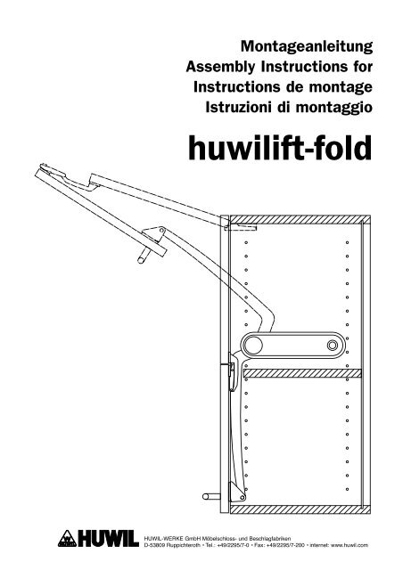
MontageanleitungAssembly Instructions forInstructions de montageIstruzioni di montaggio<strong>huwilift</strong>-<strong>fold</strong>HUWIL-WERKE GmbH Möbelschloss- und BeschlagfabrikenD-53809 Ruppichteroth • Tel.: +49/2295/7-0 • Fax: +49/2295/7-200 • internet: www.huwil.com
VorwortForewordPréfacePremessaSehr verehrter Kunde,mit der Wahl des <strong>fold</strong> haben Sie sich für einen technisch hochentwickelten und leistungsstarken mechanischen Beschlagentschieden. Ihr <strong>fold</strong> ist bei uns mit größter Sorgfalt und Präzision hergestellt worden und hat zahlreiche QualitätsundSicherheitskontrollen durchlaufen, um einen störungsfreien und sicheren Betrieb zu gewährleisten. Sie selbst könnenwesentlich dazu beitragen, dass Sie mit Ihrem <strong>fold</strong> lange Zeit zufrieden sind.1. Wichtiger Sicherheitshinweis:Der Einbau muss gemäß der Montageanleitung erfolgen, sonst besteht Verletzungsgefahr!2. Dieser <strong>fold</strong> ist ausschließlich für den Verwendungszweck als Faltdeckelstütze für Wohn- und Küchenmöbel,entsprechend dem aufgedruckten Deckelgewicht, geeignet. Jede darüber hinausgehende Verwendung gilt als nicht bestimmungsgemäß,für hieraus resultierende Schäden haftet der Hersteller nicht.Das Risiko hierfür trägt allein der Betreiber.3. Zur bestimmungsgemäßen Verwendung gehört auch die Einhaltung der vom Hersteller vorgeschriebenen Montageanweisungen.4. Berücksichtigen Sie auch die allgemeingültigen, gesetzlichen und sonstigen Regelungen und Rechtsvorschriften – auchdes Betreiberlandes – sowie die gültigen Umweltschutzbestimmungen!Die örtlich gültigen Bestimmungen der Berufsgenossenschaften oder sonstiger Aufsichtsbehörden sind immer zu beachten!5. Eigenmächtige Veränderungen am <strong>fold</strong> schließen eine Haftung des Herstellers für daraus resultierende Schäden aus.Wichtiger Sicherheitshinweis:Das Metallgehäuse des Beschlags darf keinesfalls geöffnet werden, die inneren Bauteile stehen unter starkerFederspannung! Verletzungsgefahr!Wenn Sie diese Hinweise stets beachten, werden Sie am <strong>fold</strong> lange Freude haben.Für Rückfragen stehen wir Ihnen gerne beratend zur Verfügung.Dear Customer,By choosing the <strong>fold</strong>, you have opted for a fitting solution that is technically very advanced and mechanically very efficient. Your<strong>fold</strong> is manufactured on our premises with extreme care and precision and is going through numerous quality and safety checksin order to ensure that it operates smoothly and safely. But you yourself can also make an important contribution towards ensuringthat you remain happy with your <strong>fold</strong> for a long time.1. IMPORTANT SAFETY NOTICEInstallation must be carried out in accordance with the assembly instructions; otherwise there is a risk of injury.2. The present <strong>fold</strong> is only suitable for the intended use as a <strong>fold</strong>ing flap support for living room and kitchen furniture accordingto the weight printed on the flap. Any use that falls outside this is regarded as not being an agreed use. The manufactureris not responsible for any losses or damage resulting from such use. The risks associated with this are borne by theoperator alone.3. The observance of the assembly instructions as prescribed by the manufacturer also form part of the agreed use.4. Also take into account the general legal and miscellaneous regulations and legal provisions that are applicable – eventhose that apply in the operator’s country – as well as the applicable environmental protection regulations.The regulations of the trade associations or other supervisory authorities that are in force locally must always be observed.5. The manufacturer cannot be held responsible for any losses or damage resulting from unauthorised modifications to the<strong>fold</strong>.IMPORTANT SAFETY NOTICEThe metal frame of the fixture must not be opened under any circumstances, as the internal components are springloaded and under a lot of tension and there is a risk of injury.
VorwortForewordPréfacePremessaCher client,En choisissant <strong>fold</strong>, vous avez opté pour une armature très sophistiquée sur le plan technique et très résistantesur le plan mécanique. Nous avons apporté le plus grand soin et la plus grande précision à la fabrication de votre <strong>fold</strong>.Celui-ci a subi de nombreux contrôles de la qualité et de sécurité visant à garantir un fonctionnement sûr et irréprochable.Vous contribuerez cependant vous-même à prolonger sa durée de vie.1. CONSIGNE DE SECURITE IMPORTANTE:Pour écarter tout risque de blessure, procédez à l’installation conformément aux instructions de montage.2. Cet <strong>fold</strong> est exclusivement destiné à être utilisé comme support pour battant pliant de placards et meublesde cuisine, selon le poids mentionné du battant. Toute autre utilisation sera considérée comme non conforme auxprescriptions. Le fabricant ne saurait être responsable des dommages en découlant. L’utilisateur prend seul le risque.3. Par utilisation conforme aux prescriptions on entend également le respect des instructions de montage fournies par lefabricant.4. Respectez aussi les règles et prescriptions légales ou autres généralement en vigueur – y compris celles applicablesdans le pays d’utilisation – de même que les prescriptions de protection de l’environnement!Les prescriptions locales des caisses de prévoyance contre les accidents ou d’autres autorités de contrôle doiventtoujours être respectées!5. Le fabricant ne saurait être responsable des modifications arbitraires apportées à <strong>fold</strong> ni des dommages en découlant.CONSIGNE DE SECURITE IMPORTANTE:Le boîtier métallique de l’armature ne doit être ouvert en aucun cas car les pièces qu’il contient sont soumises àune forte tension de ressort! Risque de blessure!En respectant ces consignes en permanence, vous profiterez pleinement de votre <strong>fold</strong>. Nous nous tenons à votre dispositionpour toute question et tout conseil.Egregio cliente,optando per <strong>fold</strong> ha scelto una guarnizione meccanica ad elevato sviluppo ed estremamente efficace. Abbiamo realizzato il Suoprodotto <strong>fold</strong> nel nostro stabilimento con grande cura e precisione sottoponendolo a numerosi controlli di sicurezza e qualità alfine di garantirne un funzionamento sicuro e senza disturbi. Tuttavia Lei stesso potrà dare un contributo significativo che Le permetteràdi godere a lungo del Suo <strong>fold</strong>.1. INDICAZIONI IMPORTANTI DI SICUREZZA E MONTAGGIO:Effettuare il montaggio come indicato nelle istruzioni al fine di evitare qualsiasi pericolo di incidente! Potra cosiottenere la garanzia del produttore e avere a disposizione un pronto ed efficente funzionamento dell’<strong>fold</strong>.2. Il presente <strong>fold</strong> è concepito e costruito esclusivamente come supporto coperchio per armadi e mobili da cucinae mobili in genere a seconda del peso del coperchio indicato: ogni utilizzo che esuli da tale scopo è da ritenersi non regolamentare.Il produttore non garantisce per eventuali danni derivanti da uso improprio. In tali casi il rischio deve essereassunto esclusivamente dall’operatore.3. L’utilizzo regolamentare comporta inoltre il rispetto delle indicazioni di montaggio prescritte dal produttore.4. Tenga inoltre in considerazione le norme di legge generalmente valide nonché ulteriori regolamentazioni – anche delpaese dell’operatore – unitamente alle disposizioni relative alla salvaguardia ambientale!Le disposizioni delle associazioni di categoria professionale valide a livello locale, nonché di altre autorità di sorveglianzadevono essere sempre rispettate!5. Modifiche arbitrarie all’<strong>fold</strong> escludono una garanzia del produttore per danni che ne dovessero derivare.INDICAZIONI IMPORTANTI DI SICUREZZA:La scatola non deve essere aperta per nessun motivo, i componenti contenuti sono sottoposti a forte tensione!Pericolo di ferimenti!Se seguirà sempre le indicazioni sopra riportate, il Suo <strong>fold</strong> sarà fonte di grande gioia.Per eventuali domande saremo lieti di metterci a Sua disposizione al fine di prestarLe consulenza.
1Bohrungen laut Bohrbild für das <strong>fold</strong>-Gehäuse erstellen.Drill holes for the <strong>fold</strong> frame inaccordance with the drilling diagram.Percez les trous de fixation du corps de <strong>fold</strong>conformément au gabarit.Eseguire i fori in base allo schema di foraturaper la scatola dell’<strong>fold</strong>.Schrankhöhe 600 mm, linke Schrankgehäuseseite. (Rechte Schrankgehäuseseite gespiegelt)Cabinet height 600 mm, left carcass side. (Right carcass side identical, only symmetrical)Hauteur de placard 600 mm, côté gauche. (Côté droite symétrique)Altezza armadio 600 mm, lato sinistro del corpo dell’armadio. (Lato destro del corpo dell`armadio parte contraria)(Topfbänder nach Herstellerangaben mit einem Öffnungswinkel von min. 120°)(hinge with a minimum opening angle of 120° in accordance with the manufacturer’s specifications)(Cerniere invisibili in base alle indicazioni del produttore con un angolo di apertura di min. 120°)(Charnières selon les indications du fabricant avec un angle d’ouverture de 120° min.)19*BohrungenA =Ø 5 mm x min. 12 tiefB = Kundenspezifisch je nachAuswahl der Schrauben(empfohlen 4 x 35 Schrauben)37108,5228,5BBDrilled holesA =Ø 5 mm x min. 12 deepB =customer-specific dependingon the screws selected(4 x 35 screws recommended)TrousA =dia. 5 mm x profondeur min. 12B = spécifique au client selonles vis choisies(recommandation 4 x 35 vis)Amin. 32ForiA =Ø 5 mm x min. 12 di profonditàB =Su misura per il cliente inbase alla scelta delle viti(si consigliano viti 4 x 35)335356Ø51612Ø51915314A = Bohrtiefe / Drilling depthProfondeur de percageProfondita di toratura19**= Bei anderen MaterialstärkenMaße auf Anfrage*= Dimensions for materials ofdifferent thicknesses on request*= pour les autres épaisseursde matériau, cotes sur demande*= Per materiali con altri spessorimisure su richiesta
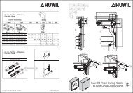
2Bohrungen laut Bohrbild für das <strong>fold</strong>-Gehäuse erstellen.Drill holes for the <strong>fold</strong> frame inaccordance with the drilling diagram.Percez les trous de fixation du corps de l’<strong>fold</strong>conformément au gabarit.Eseguire i fori in base allo schema di foraturaper la scatola dell’<strong>fold</strong>.Schrankhöhe 720 mm, linke Schrankgehäuseseite. (Rechte Schrankgehäuseseite gespiegelt)Cabinet height 720 mm, left carcass side. (Right carcass side identical, only symmetrical)Hauteur de placard 720 mm, côté gauche. (Côté droite symétrique)Altezza armadio 720 mm, lato sinistro del corpo dell’armadio. (Lato destro del corpo dell`armadio parte contraria)(Topfbänder nach Herstellerangaben mit einem Öffnungswinkel von min. 120°)(hinge with a minimum opening angle of 120° in accordance with the manufacturer’s specifications)(Cerniere invisibili in base alle indicazioni del produttore con un angolo di apertura di min. 120°)(Charnières selon les indications du fabricant avec un angle d’ouverture de 120° min.)19*BohrungenA =Ø 5 mm x min. 12 tiefB = Kundenspezifisch je nachAuswahl der Schrauben(empfohlen 4 x 35 Schrauben)37108,5228,5BBDrilled holesA =Ø 5 mm x min. 12 deepB =customer-specific dependingon the screws selected(4 x 35 screws recommended)TrousA =dia. 5 mm x profondeur min. 12B = spécifique au client selonles vis choisies(recommandation 4 x 35 vis)AForiA =Ø 5 mm x min. 12 di profonditàB =Su misura per il cliente inbase alla scelta delle viti(si consigliano viti 4 x 35)min. 3216121915Ø5Ø5367388409A = Bohrtiefe / Drilling depthProfondeur de percageProfondita di toratura19**= Bei anderen MaterialstärkenMaße auf Anfrage*= Dimensions for materials ofdifferent thicknesses on request*= pour les autres épaisseursde matériau, cotes sur demande*= Per materiali con altri spessorimisure su richiesta
3Bohrungen laut Bohrbild für das <strong>fold</strong>-Gehäuse erstellen.Drill holes for the <strong>fold</strong> frame inaccordance with the drilling diagram.Percez les trous de fixation du corps de l’<strong>fold</strong>conformément au gabarit.Eseguire i fori in base allo schema di foraturaper la scatola dell’<strong>fold</strong>.Schrankhöhe 800 mm, linke Schrankgehäuseseite. (Rechte Schrankgehäuseseite gespiegelt)Cabinet height 800 mm, left carcass side. (Right carcass side identical, only symmetrical)Hauteur de placard 800 mm, côté gauche. (Côté droite symétrique)Altezza armadio 800 mm, lato sinistro del corpo dell’armadio. (Lato destro del corpo dell`armadio parte contraria)(Topfbänder nach Herstellerangaben mit einem Öffnungswinkel von min. 120°)(hinge with a minimum opening angle of 120° in accordance with the manufacturer’s specifications)(Cerniere invisibili in base alle indicazioni del produttore con un angolo di apertura di min. 120°)(Charnières selon les indications du fabricant avec un angle d’ouverture de 120° min.)19*BohrungenA =Ø 5 mm x min. 12 tiefB = Kundenspezifisch je nachAuswahl der Schrauben(empfohlen 4 x 35 Schrauben)228,5Drilled holesA =Ø 5 mm x min. 12 deepB =customer-specific dependingon the screws selected(4 x 35 screws recommended)A37108,5BBTrousA =dia. 5 mm x profondeur min. 12B = spécifique au client selonles vis choisies(recommandation 4 x 35 vis)ForiA =Ø 5 mm x min. 12 di profonditàB =Su misura per il cliente inbase alla scelta delle viti(si consigliano viti 4 x 35)min. 3216121915Ø5Ø5398419440A = Bohrtiefe / Drilling depthProfondeur de percageProfondita di toratura19**= Bei anderen MaterialstärkenMaße auf Anfrage*= Dimensions for materials ofdifferent thicknesses on request*= pour les autres épaisseursde matériau, cotes sur demande*= Per materiali con altri spessorimisure su richiesta
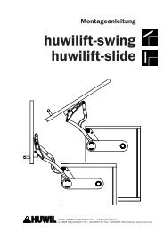
4Bohrungen laut Bohrbild für die 2-teiligenSchrankdeckel erstellen.Drill holes for the cabinet flap which comes in 2 partsin accordance with the drilling diagram.Percez les trous de fixation du battant en deux partiesconformément au gabarit.Eseguire i fori in base allo schema di foraturaper le due ante.Ausführung für Span- und MDF-Platte.Design for particle board and MDF board.Modèle pour aggloméré et MDF.Versione per pannello di truciolato e MDF.Ab 900 mm Deckelbreiteempfehlen wir3 MittelscharniereFor a flap width of 900 mm upwardswe recommend 3 central hinge jointsA partir d’une largeur de battantsupérieure à 900 mm, nous vousrecommandons d’utiliser3 charnières centrales.A partire da una larghezzadell’anta di 900 mm consigliamo3 cerniere centraliØ5Ansicht DeckelrückseiteMittelscharnierView of flap supports on thereverse side of the flap frameVue du dos du battantcharnière centraleVista lato posterioredell’anta Cerniera centraleAnzahl und Bohrbildfür Topfscharnierlaut HerstellerangabeNumber of drilled holes anddrilling diagram for hinge joint asper manufacturer’s specificationNombre et gabarit deperçage pour charnière selonles indications du fabricantNumero e schema di foraturaper cerniera invisibile in basea indicazioni del produttoreØ5141421414264 32Only mark and punch for Ø 4 mm x 8 deep woodscrews32or for euroscrews according to the drilling pattern8215316 16Nur ankörnen für Holzschrauben Ø 4 mm x 8 tiefoder für Euroschrauben entsprechend bohrenUniquement centrage pour vis à bois dia. 4 mm etprofondeur 8 ou perçage de trous pour vis euroSolo bulinatura perviti da legno Ø 4 mm x 8 di profonditàoppure foratura adeguata per eurovitiAnsicht DeckelrückseiteKlappenlagerView of flap supports on thereverse side of the flapVue dos du battantpattes de fixationVista lato posteriore dell’antasupporto anta*= Bei anderen MaterialstärkenMaße auf AnfrageOberkante BodenUpper edge of baseBord supérieur fondSpigolo superiore Fondo19*16 16532164InnenkanteSeitenwandInside edge ofside wallBord intérieurcloisonSpigolo internofianco83*= Dimensions for materials ofdifferent thicknesses on request*= pour les autres épaisseurs de matériau,cotes sur demande*= Per materiali con altri spessorimisure su richiestaHinweis:Klappenlager Bohrungen inDeckelrückseite. Maße abOberkante des Bodens, bzw.Innenkante der Seitenwand.Advice:Drill holes for the flap supportson the reverse side of the flap.Dimensions from the upper edgeof the base or the inside edgeof the side wall.Remarque:Trous pour pattes de fixation audos du battant. Cotes à partirdu bord supérieur du fond ou dubord intérieur de la cloison.Avvertenza:Fori nei supporti delle antenella parte posterioredell’anta. Misure a partiredallo spigolo superioredel fondo/dallo spigolointerno fianco.
5Bohrungen laut Bohrbild für die 2-teiligenSchrankdeckel erstellen.Drill holes for the cabinet flap which comes in 2 partsin accordance with the drilling diagram.Percez les trous de fixation du battant en deux partiesconformément au gabarit.Eseguire i fori in base allo schema di foraturaper le due ante.Ausführung für 20 mm Alu-Rahmenprofil.Design for 20 mm aluminium frame profile.Modèle pour profilé en aluminium 20 mmVersione per profilo del telaio in alluminio di 20 mm.Ab 900 mm Deckelbreiteempfehlen wir3 MittelscharniereAnzahl und Bohrbildfür Topfscharnierlaut HerstellerangabeFor a flap width of 900 mm upwardswe recommend 3 central hinge jointsA partir d’une largeur de battantsupérieure à 900 mm, nous vousrecommandons d’utiliser3 charnières centrales.A partire da una larghezza dell’antadi 900 mm consigliamo3 cerniere centraliAnsicht Deckelrahmen-RückseiteMittelscharnierView of central hinge joint on thereverse side of the flap frameVue du dos de la structuredu battant charnière centraleVista parte posteriore del telaiodell’anta Cerniera centraleNumber of drilled holes anddrilling diagram for hinge joint asper manufacturer’s specificationNombre et gabarit deperçage pour charnière selonles indications du fabricantNumero e schema di foraturaper cerniera invisibile in basea indicazioni del produttore20Ø5Ø5141421414216 1616 16Kundenspezifisch je nachAuswahl der Schrauben empfohlen64 32M4 oder Blindnieten Da = 4 mm32Ansicht Deckelrahmen-RückseiteKlappenlagerView of flap supports on thereverse side of the flap frameVue dos de la structure dubattant pattes de fixationVista parte posteriore del telaiodell’anta supporto anta215319*Customer-specific depending on thescrews selected recommended:M4 screws or rivets with Da = 4 mmSpécifique au client selon lesvis choisies Recommandation:Vis M4 ou rivets aveugles Da = 4 mmSu misura per il cliente in base allascelta delle viti. Si consigliaapplicare bussole M4 per viti M4.Oberkante BodenUpper edge of baseBord supérieur fondSpigolo superiore Fondo5364InnenkanteSeitenwandInside edge ofside wallBord intérieurcloisonSpigolo internodel fianco211,5*= Dimensions for materials ofdifferent thicknesses on request*= Bei anderen BodenstärkenMaße auf Anfrage*= pour les autres épaisseurs de matériau,cotes sur demande*= Per materiali con altri spessorimisure su richiesta7Hinweis:Bohrungen inDeckelrahmen.Maße ab Oberkantedes Bodens,bzw. Innenkante derSeitenwand.Siehe auch Abb. 10 + 12Advice:Drill holes inthe flap frame.Dimensions from theupper edge of thebase or the insideedge of the wall.See also Figs. 10 + 12Remarque:Trous dans lastructure du battant.Cotes à partir du bordsupérieur du fond oudu bord intérieur dela cloison. Voirégalement fig. 10 + 12Avvertenza:Fori nel telaiodell’anta.Misure a partire dallospigolo superioredel fondo/dallo spigolointerno dell fianco.Vedi anche figure 10 + 127
6Mittelscharniere an 2-teiligen Schrankdeckelanschrauben.Screw the central hinge joints onto the cabinet flapwhich comes in 2 parts.Vissez les charnières centrales sur le battanten 2 parties.Avvitare le cerniere centrali.Ausführung für Span- und MDF-Platte.Design for particle board and MDF board.Modèle pour aggloméré et MDF.Versione per pannello di truciolato e MDF.7Ausführung für Alu- Rahmenprofil.Design for Aluminium frame profile.Modèle pour profilé en aluminium.Versione per profilo del telaio in alluminio.Avvertenza:Si consiglia di applicare le cerniera centralealle due ante di alluminio con molda attenzionee sicurezza, adoperone possibilmente bussole.
8Klappenlager an unteren Schrankdeckelanschrauben.Screw flap supports onto bottom part ofcabinet flap.Vissez la patte de fixation sur le battantinférieur du placard.Avvitare i supporti sull’anta inferiore.Ausführung für Span- und MDF-Platte.Design for particle board and MDF board.Modèle pour aggloméré et MDF.Versione per pannello di truciolato e MDF.9Ausführung für Alu- Rahmenprofil.Design for Aluminium frame profile.Modèle pour profilé en aluminium.Versione per profilo del telaio in alluminio.
10Topfscharniere an oberen Schrankdeckel nachHerstellerangabe vormontieren.Pre-mount hinges on the top of cabinet flap in accordance withthe manufacturer’s specifications.Procédez au montage préliminaire des charnières sur le battantsupérieur du placard conformément aux indications du fabricant.Pre-montare le cerniere invisibili sull’anta superiorein base alle indicazioni del produttore.11Möbelgriff an unteren Schrankdeckel innerhalbdes markierten Bereichs montieren.Mount the cabinet handle on the bottom part of cabinet flapwithin the area marked.Montez la poignée du meuble sur le battant inférieur duplacard sous la zone marquée.Montare la maniglia sull’anta inferiore all’internodello spazio marcato.Empfohlene optimale Griffhöhe 29 mm von Oberkante Schrankboden.Optimum recommended handle height is 29 mm from the upper edge of the base of the cabinet.Hauteur de poignée optimale recommandée 29 mm à partir du bord supérieur du fond du placard.Altezza ottimale consigliata della maniglia: 29 mm dallo spigolo superiore del fondo dell’armadio.1929
12Rechtes und linkes <strong>fold</strong>-Gehäuse anschrauben.Screw on the right and left <strong>fold</strong> frame.Vissez le corps de l’<strong>fold</strong> sur les côtés gauche et droit.Avvitare le scatole destra e sinistra dell’<strong>fold</strong>.Achtung!Hebelarm des <strong>fold</strong> Gehäuses muss sich in Offenstellung (Lieferzustand) befinden, sonstVerletzunggefahr! Beschlag steht unter Federspannung.Please NoteThe lifting arm of the <strong>fold</strong> frame must be in the open position (supply condition) asotherwise there is a risk of injury.Attention!Le bras de levier du corps de l’<strong>fold</strong> doit se trouver en position ouverte (état à la livraison).Sinon, risque de blessure!Attenzione!Il braccio di leva della scatola dell’<strong>fold</strong> deve trovarsi in posizione aperta (come al momentodella consegna), diversamente sussiste pericolo di ferimenti!*)*= Euroschraube für 5 mm BohrungSenkkopf Ø 7,8 mm, Länge min. 13 mmGrobgewinde (Steigung 2,2 mm).*= Euro srew for 5 mm holecounter sunk Ø 7,8 mm, length min. 13 mmcoarse thread, (profession 2,2 mm).*= Vis Euro pour 5 mm de perçagevis moyée Ø 7,8 mm, longueur min. 13 mmFiletage (progression 2,2 mm).*= Viti europeee per perforazione di 5 mmTesta incassata Ø 7,8 mm, lunghezza min. 13 mmFilettatura (gradiente 2,2 mm).*)
13Schrankdeckel in Topfbänder einhängenund fixieren.Insert the cabinet flap into the hingesand fix securely.Installez le battant du placarddans les charnières et fixez-le.Agganciare e fissare l’anta allecerniere invisibili.Wir empfehlen:Kreuz-Montageplatten mit drei Befestigungslöchern.We recommendcross mounting plates with three mounting holes.Recommandation:Plaques de montage en croix avec trois trousde fixation.Consigliamo pannelli a montaggio incrociato con trefori di fissaggio.14Hebelarme (Offenstellung) in die Klappenlager einclipsenund mit Sprengringen sichern.Clip lifting arms (open position) into the flap supportsand secure with circlips.Insérez les bras de levier (position ouverte) dans lespattes de fixation et fixez-les à l’aide de bagues.Inserire i bracci di leva (posizione aperta) nei supportidelle ante e fissare con anelli di sicurezza.Ausführung für Span- und MDF-Platte.Design for particle board and MDF board.Modèle pour aggloméré et MDF.Versione per pannello di truciolato e MDF.
15Hebelarme (Offenstellung) in die Klappenlager einclipsenund mit Sprengringen sichern.Clip lifting arms (open position) into the flap supportsand secure with circlips.Insérez les bras de levier (position ouverte) dans lespattes de fixation et fixez-les à l’aide de bagues.Inserire i bracci di leva (posizione aperta) nei supportidelle ante e fissare con anelli di sicurezza.Ausführung für Alu- Rahmenprofil.Design for Aluminium frame profile.Modèle pour profilé en aluminium.Versione per profilo del telaio in alluminio.16Gehäuseabdeckung auf die <strong>fold</strong> Gehäuse aufclipsen.Clip the frame cover onto the <strong>fold</strong> frame.Installez le cache sur le corps de l’<strong>fold</strong>.Incastrare la protezione sulla scatola dell’<strong>fold</strong>.Linke und rechte Seite.Left and right side.Côtés gauche et droit.Lato sinistro e destro.
17Auf rechter und linker Schrankseite gleichmäßig <strong>fold</strong>auf Deckelgewicht einstellen.Adjust the <strong>fold</strong> evenly on the right and left side ofthe cabinet to take the weight of the flap.A droite comme à gauche du placard, réglez l’<strong>fold</strong> demanière uniforme en fonction du poids du battant.Mettere a punto in modo uniforme l’<strong>fold</strong> sul latodestro e sinistro dell’armadio in base al peso dell’ante.Einstellschraube 1 mit Imbusschlüssel SW 10 durch Drehung im Uhrzeigersinn, max. bis zum Anschlag,nach Bedarf einstellen, bis der Schrankdeckel in jeder beliebigen Position gehalten wird. Abdeckstopfen 2aufdrücken.Adjust positioning screw 1 as required by using an SW 10 size allen key and turning it in a clockwisedirection, max. till end position, until the cabinet flap is held in any position that may be desired. Presson cover plug 2.Si nécessaire, réglez la vis 1 en la tournant en sens horaire, maximum jusqu’au bout, à l’aide d’une cléhexagonale SW 10 jusqu’à ce que le battant soit fixé dans la position souhaitée. Installez le cache 2.Mettere a punto la vite di regolazione 1 in base alle esigenze servendosi di una chiave esagonaSW 10 e girando in senso orario, massimo fino all’arresto, finché l’anta possa essere sostenuta inogni posizione desiderata. Premervi sopra il tappo di sicurezza 2.1SW 10218Funktionsprüfung durchführen.Carry out functional test.Vérifiez que tout fonctionne bien.Eseguire verifica di funzionamento.Bei richtiger Einstellung hält der Schrankdeckel in jeder Position.If everything has been adjusted correctly the cabinet flap will stop in any position.Lorsque le réglage est correct, le battant du placard tient dans n’importe quelle position.Con la messa a punto adeguata l’anta tiene in ogni posizione.
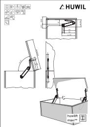
19Auswahl der richtigen <strong>fold</strong>-AusführungChoosing the correct <strong>fold</strong> modelChoix du modèle correct d’<strong>fold</strong>Scelta della versione appropriata dell’<strong>fold</strong>Die richtige Ausführung des <strong>fold</strong>ergibt sich aus Höhe und Gewichtdes Schrankdeckels. Siehe Tabelle.El modelo correcto del <strong>fold</strong> se eligeen función de la altura, del ancho y del pesode las tapas del mueble. Véase tabla.La versione appropriata dell’<strong>fold</strong> sideduce dall’altezza, dalla larghezza e dalpeso dell’anta. Vedi tabella.[ mm ]GewichtWeightPoidsPeso[ kg ]SchrankhöheCabinetHeightHauteur duplacardAltezzaarmadioAusführungModelModèleVersioneGewichtWeightPoidsPeso[ kg ]AusführungModelModèleVersioneGewichtWeightPoidsPeso[ kg ]AusführungModelModèleVersioneje 2 Klappenhalter / 2 lid-stays / pour 2 compas / 2 snodi600 6,0 – 6,7 A 10 6,8 – 8,1 A 20 8,2 – 10,0 A 307208005,3 – 6,5 B 10 6,6 – 8,7 B 20 8,8 – 11,0 B 305,0 – 6,1 C 10 6,2 – 8,0 C 20 8,1 – 10,0 C 30GewichtWeightPoidsPeso[ kg ]AusführungModelModèleVersioneGewichtWeightPoidsPeso[ kg ]AusführungModelModèleVersione10,1 – 13,0 A 40 13,1 – 16,2 A 5011,1 – 13,3 B 40 13,4 – 14,8 B 5010,1 – 12,5 C 40 12,6 – 13,5 C 50Sonderbreiten Beispielspecial widthlargeur spécialelarghezze spescialiGewichtWeightPoidsPeso[ kg ]1800AusführungModelModèleVersioneje 3 Klappenhalter erforderlich3 lid-stays requiredPour 3 compas nécessairemontare 3 snodi9,0 – 10,1 A 1010,2 – 12,2 A 2012,3 – 15,8 A 3015,9 – 20,2 A 4020,3 – 24,3 A 507,9 – 9,8 B 109,9 – 13,1 B 2013,2 – 16,6 B 3016,7 – 20,0 B 4020,1 – 22,2 B 507,5 – 9,2 C 109,3 – 12,2 C 2012,3 – 15,7 C 3015,8 – 18,8 C 4018,9 – 20,2 C 5012 0001 010 207 QFS 516 1.00 12 02 Eng 5Weitere Ausführungen auf Anfrage!Maßangaben unverbindlich – Technische Änderungen vorbehalten!Details of other models are available on request!Given dimensions are not binding – we reserve the right for technical modifications!Autres modèles sur demande!Dimensions sans engagement de notre part – modifications techniques réservées!Ulteriori versioni su richiesta!Le misure senza alcun impegno da parte nostra. Cambiamenti tecnici riservati!