2722 Master room unit QAX850
2722 Master room unit QAX850
2722 Master room unit QAX850

Create successful ePaper yourself
Turn your PDF publications into a flip-book with our unique Google optimized e-Paper software.
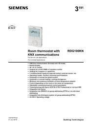
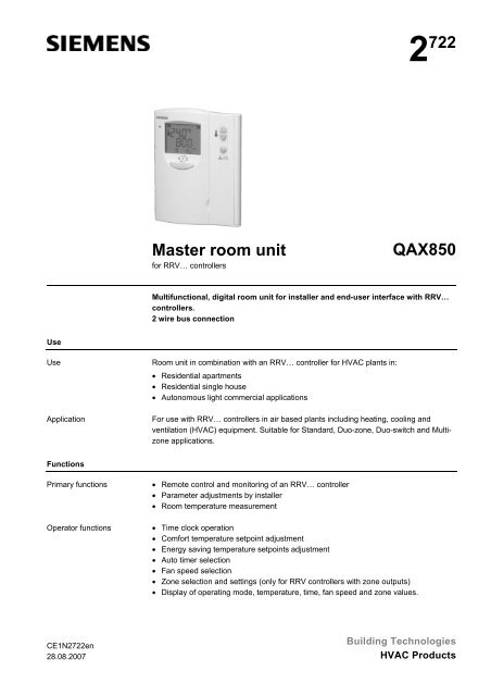
2 722<strong>Master</strong> <strong>room</strong> <strong>unit</strong>for RRV… controllers<strong>QAX850</strong>Multifunctional, digital <strong>room</strong> <strong>unit</strong> for installer and end-user interface with RRV…controllers.2 wire bus connectionUseUseApplicationRoom <strong>unit</strong> in combination with an RRV… controller for HVAC plants in:• Residential apartments• Residential single house• Autonomous light commercial applicationsFor use with RRV… controllers in air based plants including heating, cooling andventilation (HVAC) equipment. Suitable for Standard, Duo-zone, Duo-switch and Multizoneapplications.FunctionsPrimary functionsOperator functions• Remote control and monitoring of an RRV… controller• Parameter adjustments by installer• Room temperature measurement• Time clock operation• Comfort temperature setpoint adjustment• Energy saving temperature setpoints adjustment• Auto timer selection• Fan speed selection• Zone selection and settings (only for RRV controllers with zone outputs)• Display of operating mode, temperature, time, fan speed and zone values.CE1N<strong>2722</strong>en28.08.2007Building TechnologiesHVAC Products
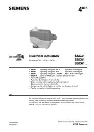
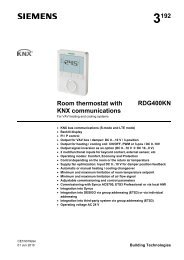
LCD display1<strong>2722</strong>Z014267351481391210 111 Day indication2 Actual temperature3 Fahrenheit/Celsius4 Zone indication (RRV856 and RRV852 for Duo-switch application)5 AM/PM indication6 Time display7 System off8 Comfort mode (Day zone in Duo-zone application)9 Energy saving mode (Night zone in Duo-zone application)10 Auto timer mode11 Heating mode12 Cooling mode13 Fan speed indication (low, medium and high)14 Auto fan modeCommissioning notesResponse on start-upSensor calibrationCommissioningWhen powering up, the <strong>QAX850</strong> will display all LCD icons for approximately 3 secondsand then the software version number for another 3 seconds. It will then revert tonormal display. The time segments will be blinking if time needs to be set. Set time asper Operation Instructions. There will be a delay before operation commences due topolling of all values.Generally there is no need to calibrate sensor; however the displayed <strong>room</strong>temperature on the LCD can be calibrated if there is any discrepancy from the actualtemperature measured with a certified thermometer. Calibration function can beaccessed by pressing the and buttons simultaneously for 5 seconds. Displayedvalue can then be adjusted via the same buttons in 0.1K steps. Range is ±3 K.Initial application set-up of RRV controller to match the connected HVAC equipment ismade by the selection of dip switch positions. Dip switches are located on the top of theRRV controller. Further settings can be made via the <strong>QAX850</strong> by modifying parametersas per list below. Default values are dependant on application selected and RRVcontroller model. Refer to Installation Instructions for set-up details and applicationsheets for default parameter values.To access parameters press the and buttons simultaneously for 3 seconds, thenwithin 2 seconds press the button for 3 seconds and release. Parameters cannot beaccessed if system is in off mode.Set-up parametersNo. Parameter RangeP00 Temperature scale °C/F°P01 Frost protection limit in OFF mode Off/5…8 °CP02 Over-temperature limit in OFF mode Off/30…35 °CP03 Min. OFF time delay 0…600 sP04 Min. ON time delay 0…600 sP05 Dead band between cool and heat OFF points 0.5…6 KSiemens <strong>Master</strong> <strong>room</strong> <strong>unit</strong> <strong>QAX850</strong> CE1N<strong>2722</strong>enBuilding Technologies 28.08.20073/7
No. Parameter RangeP06 RV ON in heat or cool mode Heat/CoolP07 Fan run ON after heat output turns Off 0…300 sP08 Fan run ON after cool output turns Off 0…300 sP09 FCU flush pipe time 120…600 sP10 Zone Heat / Cool Inhibit Heat/Cool/NoP11 Water temp. heat mode changeover 22…32 °CP12 Water temp. cool mode changeover 10…21 °CP13 Fan auto-speed high range H:80…100 %P14 Fan auto-speed medium range M:30…75 %P15 Fan auto-speed low range L:1…15 %P16 Window contact NO/NCP17 2-p or 3-p control selection 2-p/3-pP18 P-band in heat mode /Switching differential 0.5…10 KP19 P-band in cool mode /Switching differential 0.5…10 KP20 Integration time 0…60.0 min in0.5 min stepsP21 3-p valve actuator running time 50…300 sP22 Zone capacity weight NoneSmallMediumLargeP23 Ventilation in dead zone Off, H/C, C onlyInternal sensor<strong>QAX850</strong> internal sensor can be replaced by connecting an external NTC resistorsensor (QAA32 or QAH11) to the RRV controller B1 input. In this case the <strong>QAX850</strong>automatically recognizes and displays the external sensor value.Mounting and installation notesThe <strong>QAX850</strong> should be mounted in a location where the air temperature can bemeasured as accurately as possible without getting adversely affected by direct solarradiation or other heating or cooling sources. There is no need to consider airtemperature conditions if external sensor is connected to the RRV controller. In thiscase the <strong>QAX850</strong> would serve as a master control <strong>unit</strong> only.• Mounting height is about 1.5 m above the floor.• <strong>QAX850</strong> must not be located in the direct path of air conditioning air flow.• The <strong>unit</strong> can be fitted to a recessed conduit box.• The specified ambient conditions must be complied with.• Only authorized staff may disconnect the <strong>QAX850</strong> <strong>unit</strong> from base plate.• Do not mount in recesses, shelves, behind curtains or doors.• Refer to Mounting Instructions M2721 included in packaging box.When mounting the <strong>unit</strong>, fix the base-plate first and then make the electricalconnections. To avoid any damage during construction works only install <strong>QAX850</strong> <strong>unit</strong>4/7Siemens <strong>Master</strong> <strong>room</strong> <strong>unit</strong> <strong>QAX850</strong> CE1N<strong>2722</strong>enBuilding Technologies 28.08.2007
when all construction works have been completed. The <strong>QAX850</strong> must be mounted on aflat surface and in compliance with local regulations.Local installation regulations must be observed.STOP NoteThe <strong>room</strong> <strong>unit</strong> is not protected against connection to AC 230 V!Technical dataInterfaces (S+, SG) HCC bus proprietary protocolBus power supply voltageDC 12 V, +10, –15% (supplyRRV85x controller)Baud rate9.6 kbit/sRoom <strong>unit</strong> power consumption2 VAPermissible cable lengthsElectrical connections(HB+, HB–)For bus communicationA ≥0.5 mm²A ≥1 mm²Type of cableNote:Twisted pair (unshielded) is recommended for enhancedimm<strong>unit</strong>y to external electromagnetic interference, e.g. in thevicinity of radio transmitters or variable speed drivesConnection terminalsFor wiresmax. 60 mmax. 100 m2-wire standard installation cable(unshielded)screw terminals0.6 mm dia. … 2.5 mm 2Degrees of protection Degree of protection of housing to IEC 60 529 IP 30Safety class to EN 60 730device suited for use with equipmentof safety class IIEnvironmental conditionsOperation toClimate conditionsTemperature (housing and electronics)HumidityMechanical conditionsTransport toClimate conditionsTemperatureHumidityMechanical conditionIEC 721-3-3class 3K50…50 °C5…95 % r. h. (non-condensing)class 3M2IEC 721-3-2class 2K3–25…+70 °C
Electromagnetic compatibilityImm<strong>unit</strong>y domestic section, light industryEmissions domestic section, light industry-conformityEMC directiveLow-voltage directiveN474 conformity toAustralian EMC frameworkRadio interference emission StandardEN 61 000-6-1EN 61 000-6-389/336/EEC73/23/EECRadio Communication Act 1992AS/NZS 4251.1Room temperature Measuring range 0…49 °Cmeasurement Setpoint range 5…35 °CAccuracy at 20 °Cmax. ±0.5 KTemperature calibration rangemax. ±3.0 K in increments of 0.5 KRoom temperature display resolution0.5 KWeight Excluding packaging approx. 0.1 kgNotesProduct liability• The products may only be used in building services plant and applications asdescribed above.• When using the products, all requirements specified under ”Technical data” must beobserved.• Local regulations for electrical installations must be complied with.Connection diagramHB+HB-HB+HB-2723A01N1A1A1N2<strong>QAX850</strong> master <strong>room</strong> <strong>unit</strong>RRV… controller6/7Siemens <strong>Master</strong> <strong>room</strong> <strong>unit</strong> <strong>QAX850</strong> CE1N<strong>2722</strong>enBuilding Technologies 28.08.2007
DimensionsRoom <strong>unit</strong>1193031M019623,8Base428 283528411,83028112,326 3089,453031M02Dimensions in mm©2005 Siemens Switzerland LtdHVAC Products7/7Siemens <strong>Master</strong> <strong>room</strong> <strong>unit</strong> <strong>QAX850</strong> CE1N<strong>2722</strong>enBuilding Technologies 28.08.2007