1518 Room Hygrostats QFA1⦠- Azimut Kft.
1518 Room Hygrostats QFA1⦠- Azimut Kft.
1518 Room Hygrostats QFA1⦠- Azimut Kft.

You also want an ePaper? Increase the reach of your titles
YUMPU automatically turns print PDFs into web optimized ePapers that Google loves.
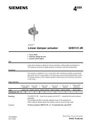
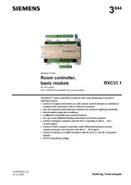
1 518QFA1001QFA1000<strong>Room</strong> <strong>Hygrostats</strong>for relative humidityQFA1…• Hygrostat with single-pole microswitch• Humidity measuring element made of stabilized plastic texture• Setpoint knob for the upper switching point• For controlling humidification equipment• For controlling dehumidification equipment• For mounting directly on the wall or on a recessed conduit boxUseThe room hygrostats are used for controlling and monitoring relative humidity in ventilationor air conditioning plant.They ensure room humidity control within the selectable range of 30 to 90 % relativehumidity by controlling humidification or dehumidification equipment.They can also be used for monitoring minimum or maximum humidity levels.Type summaryType Setpoint setting Switching differential 1)Setpointreference range Statically Dynamically knobQFA1000 30…90 % r. h. Approx. 4 % r.h. 6 % r.h. InternallyQFA1001 30…90 % r. h. Approx. 4 % r.h. 6 % r.h. Externally1) The static switching differential is determined at a constant ambient humidity by turning the settingknob.The dynamic switching differential is determined by changing the ambient humidity while maintainingthe same setpoint adjustment; only the dynamic switching differential is of practical value.CE1N<strong>1518</strong>en04.12.2007 Building Technologies
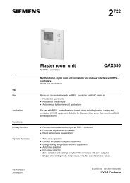
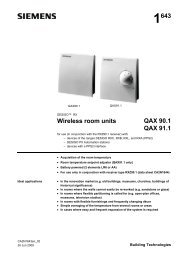
OrderingWhen ordering, please give name and type reference, e.g.:<strong>Room</strong> hygrostat QFA1001Mode of operationThe room hygrostat acquires the relative humidity of the ambient air via its humiditymeasuring element, which is made of stabilized plastic texture. This plastic band actuatesa microswitch depending on the relative humidity. The microswitch has a fixedswitching differential XSd and a potential-free contact output. If the actual humidity deviatesfrom the adjusted setpoint, the hygrostat switches the humidification or dehumidificationequipment as shown in the following function diagram.Function diagramr. F. [%]x<strong>1518</strong>D01dewX Sd3S1 1 2ttLegend:r. h. Relative humidity in %S1 Microswitch1-2 Humidification1-3 Dehumidificationw Setpoint = upper switching pointx Actual valueX Sd Switching differentialt TimeDue to the measuring element’s aging effect, the switching point drifts slowly and constantly.For this reason, recalibration may be required in due time.At temperatures other than the calibration temperature, the switching point drifts systematically(temperature influence). Also, in the case of fast humidity changes, theswitching point will temporarily be shifted.Mechanical designQFA1001QFA1000The room hygrostat is designed for wall mounting. It fits on most commercially availablerecessed conduit boxes. The cables are introduced either from the rear (recessed conduitboxes) or from above (surface-run wires), after knocking out the cable inlettongues.The unit consists of base and cover.Base and cover can be separated (snap-on connection).The base accommodates the humidity measuring element, setpoint setting elementwith setting spindle, scale, microswitch and screw terminals.The cover carries the removable setpoint knob with its imprinted scale.This model is of the same basic design as the QFA1001, but there is no external setpointknob. The setpoint can only be adjusted when the cover is removed.2/4Siemens <strong>Room</strong> hygrostats QFA1001, QFA1000 CE1N<strong>1518</strong>enBuilding Technologies 04.12.2007
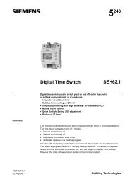
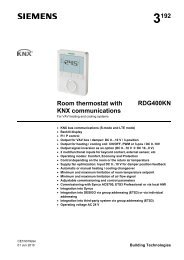
7040Operating elements<strong>1518</strong>Z0180907060605050 301 2 3Legend1 Setpoint knob with scale – only with QFA10012 Setpoint setting spindle3 Scale for setpoint adjustment with QFA1000Mounting notesMounting choicesMounting locationMounting InstructionsThe base has cable entries at the rear for mounting the room hygrostat on recessedconduit boxes. In the case of wall mounting, appropriate holes at the top or bottom canbe knocked out.The unit should be mounted about 1.5 meters above the floor and at least 0.5 metersfrom the closest wall.Natural circulation of room air must be ensured at the location where the hygrostat ismounted (no drafts, not in corners, not behind curtains, not in the vicinity of doors andwindows, and not on outer walls). Sources of heat or refrigeration (radiators, computers,TV sets, concealed heating pipes, hot and cold water pipes) must be located atadequate distances.The unit must not be exposed to direct solar radiation.The room hygrostat is supplied complete with Mounting Instructions.Technical dataFunctional dataProtective dataElectrical connectionEnvironmental conditionsMaterials and colorsStandardsWeightSetpoint setting range 30…90 %Humidity measuring elementstabilized plastic texture bandControl mode2-positionTime constant (v = 0.2 m/s)approx. 5 minSwitching differential X Sdrefer to "Type summary"Setting accuracy 1)± 5 % r.h.Temperature influence+ 0.5 % r.h. / KHumidity calibration at 55 % r.h., 23 °CLong-term stabilityapprox. − 1.5 % r.h. / aType of switchContact ratingMaximumMinimummicroswitch (1-pole potential-free changeover switch)5(3) A, AC 250 V100 mA, AC 24 VDegree of protection of housing IP20 to EN 60 529Safety class II to EN 60 730Screw terminals for max. 2 x 1.5 mm 2Perm. ambient temperatureNoncondensingBaseCoverHumidity measuring elementCE conformity toEMC directiveLow-voltage directiveQFA1001QFA10000...40 °C− 25...+ 40 °CPPS Fortron, glassfiber-reinforced, blackPC Lexan 940, pure-whiteplastic texture89/336/EEC73/23/EEC0.090 kg0.090 kg1) Can be improved by recalibrating on siteSiemens <strong>Room</strong> hygrostats QFA1001, QFA1000 CE1N<strong>1518</strong>enBuilding Technologies 04.12.20073/4
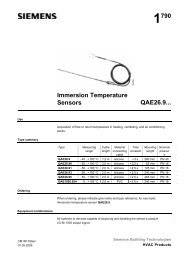
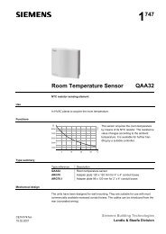
75Connection diagramsInternal diagram12 3ϕ<strong>1518</strong>G011-2 Humidification1-3 DehumidificationConnection diagramsDiagram 1: HumidificationDiagram 2: DehumidificationLAC 230 VNT5A12 3+ ϕϕ<strong>1518</strong>A01LAC 230 VNT5A12 3– ϕϕ<strong>1518</strong>A02..........DimensionsQFA1000, QFA100160<strong>1518</strong>M014809070766050 304,27634Dimensions in mm4/4©2004 – 2007 Siemens Switzerland Ltd Subject to alterationSiemens <strong>Room</strong> hygrostats QFA1001, QFA1000 CE1N<strong>1518</strong>enBuilding Technologies 04.12.2007