HRC3.2 Room controller
HRC3.2 Room controller
HRC3.2 Room controller

You also want an ePaper? Increase the reach of your titles
YUMPU automatically turns print PDFs into web optimized ePapers that Google loves.
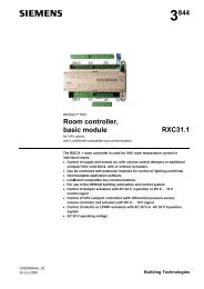
Mechanical designThe <strong>HRC3.2</strong> <strong>controller</strong> consists of a housing base, a housing cover and a printed circuitboard with connection terminals.The <strong>controller</strong> also has a tool socket, a service LED and a service pin.Cable restraintsConnectionterminalsConnection terminals for roombusConnector for service toolHousing coverConnectionterminalsHousing base6314z02Device labelOpen EnergyManagementEquipment22K4C USLISTED6314z03NoteUse of the labeling fields for handwritten entries:AdrAppl.LocKonnex addressCurrently loaded application<strong>Room</strong> numberTerminal coversSTOPCaution6314z04Owing to the intrinsic heat generated by the<strong>controller</strong>, terminal covers must not be used,as this can cause overheating.For the same reason, adequate aircirculation must be provided in the locationwhere the <strong>controller</strong> is installed.Protection from physicalcontactTo prevent accidental physical contact with relay connections carrying voltages inexcess of the SELV voltage range (U eff > 42), the device must be fitted in a housing(preferably a control panel). This enclosure must be accessible only by use of akey or tool.Alternatively, a commercially available contact guard can be used.4/12Siemens <strong>HRC3.2</strong> – <strong>Room</strong> <strong>controller</strong> CM2N6314enBuilding Technologies 01.09.2008