HRC3.2 Room controller
HRC3.2 Room controller
HRC3.2 Room controller

Create successful ePaper yourself
Turn your PDF publications into a flip-book with our unique Google optimized e-Paper software.
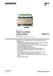
ConnectionsInterface layoutX1 X2 X3J1X4 X5 X66314z08Interfaces:X1: AC 24V +/–10% supply voltage / Triac outputsX2: Digital inputs DC 12VX3: Building bus and room bus (RS485)X4: 7 relay outputs max. AC 230 VX5: 4 relay outputs max. AC 230 VX6: 12V supply voltage for LED indicators and door opener 0J1: Service socket (RS232): 10-pin Use special service cable!Connection diagramsThe following functions are valid for the standard applicationTerminal block X1AC 24 V supplyTriac outputsPin I/O Function1 G AC 24 V supply2 G0 AC 24 V supply3 T 1 Heating valve open Max. 0.5 A, 12 VA 1)4 G05 T 2 Heating valve closed Max. 0.5 A, 12 VA 1)6 T 3 Cooling valve open Max. 0.5 A, 12 VA 1)7 G08 T 4 Cooling valve closed Max. 0.5 A, 12 VA 1)STOPCaution1)Total of all Triac outputs: Max. 12 VA for all outputse.g.: 4 outputs, each 3 VA (see information marked on device)Terminal block X2Digital inputsDC 12 V1 DI 1 "Service call" or "Make up room" button2 DI 2 "Do not disturb" button3 DI 3 "SOS / Call for Assistance" button4 DI 4 RH4 "Courtesy light" button5 GND6 DI 5 RH7 "Master light" button7 DI 6 “Guest in room” switchGuest in room = contact closed8 DI 7 Window monitoring contactWindow closed = Contact closed9 DI 8 Door monitoring contact:Door closed = Contact closed10 GND10/12Siemens <strong>HRC3.2</strong> – <strong>Room</strong> <strong>controller</strong> CM2N6314enBuilding Technologies 01.09.2008