HRC3.2 Room controller
HRC3.2 Room controller
HRC3.2 Room controller

Create successful ePaper yourself
Turn your PDF publications into a flip-book with our unique Google optimized e-Paper software.
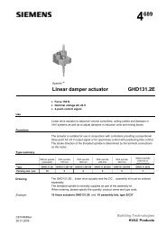
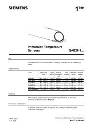
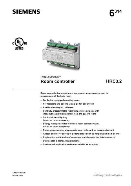
6 314HOTEL SOLUTION<strong>Room</strong> <strong>controller</strong><strong>HRC3.2</strong><strong>Room</strong> <strong>controller</strong> for temperature, energy and access control, and formanagement of the hotel room• For 2-pipe or 4-pipe fan-coil systems• For radiators and cooling via 2-pipe fan-coil system• Auxiliary heating for bathroom• Centrally programmable room temperature setpoint withindividual setpoint adjustment from the guest's room• Control of room lightingbased on room occupancy• Energy management for individual room control systembased on room occupancy• <strong>Room</strong> access control via magnetic card, chip card, or transponder card• Access control for access to general areas such as car park and main doors• Registration and transfer of messages and alarms to the database server• Downloadable standard applications• Customized application software available as an optionCM2N6314en01.09.2008 Building Technologies
UseThe <strong>HRC3.2</strong> room <strong>controller</strong> integrates temperature control, energy management,access control and the management of a hotel room, at room level.For operation, use is made of room operator units, access card readers and accesscard holders with a switch to turn on the lights, for example, and a connection to thebus.FunctionsThe functions are determined by the downloadable application software.The room <strong>controller</strong>s are delivered with the standard application (the basic features aredescribed in this data sheet).In special cases, the standard application may be overwritten with a definitivecustomized application software. A commissioning and service tool is available for thispurpose.Temperature controlThe following options can be implemented with fan-coil units:• 4-pipe heating/cooling with 3-position or PWM output• 2-pipe heating/cooling with 3-position or PWM output with changeover• 2-pipe system with internal electric heating, 2-position or PWM outputand cooling with 3-position or PWM output• 4-pipe heating via external radiatorand cooling with 3-position or PWM output• Auxiliary heating in bathroom, additional radiator or underfloor heating with2-position, 3-position or PWM output<strong>Room</strong> temperature setpoints:• Centrally programmable room comfort temperature setpoint• Individual setpoint adjustment of room comfort temperature setpoint in guest's room• PreComfort setpoints when guest is absent• Economy setpoints for free rooms (i.e. from which guests have checked out)• Remote room temperature setpoint adjustment in rooms unoccupied for long periodsEnergy-saving features:• Energy management for individual room control system and lightingbased on room occupancy:− <strong>Room</strong> occupied, guest in room− <strong>Room</strong> occupied, guest absent− <strong>Room</strong> vacant, not checked in− <strong>Room</strong> out of use, e.g. during low season• Summer/winter strategy(i.e. avoid heating in summer and avoid cooling in winter)• Fan disabled if window is openedEnergy managementElectricity:• Master switch function: to switch electrical consumers on and off• Switch-on control of courtesy light function upon entry to room• Electrical consumers enabled and disabled by pre-programmed, guest or hotel-staffdependent function• Water supply shut off in the absence of guests and hotel staff (only possible withmagnetic valve installed)2/12Siemens <strong>HRC3.2</strong> – <strong>Room</strong> <strong>controller</strong> CM2N6314enBuilding Technologies 01.09.2008
Access controlManagement levelBuilding automationand controlCommunicationNote• Control of blinds or curtain• Receipt of access code from the connected magnetic, chip or transponder cardreader• Control of access to guest rooms, suites and general access areas• Receipt of access codes for guests, hotel staff and emergency access cards fromthe central management station at the reception• Management of all access codes• Activation of door opening mechanism when access is granted• SOS alarm or bathroom alarm• "Do not disturb" and "<strong>Room</strong> service call" or "Make up room"• "Guest present" indicator for hotel staff only• Bell disabled in conjunction with "Do not disturb"• Alarm message if door is opened in unoccupied room (door intrusion)• Alarm message if window is opened in unoccupied room (window intrusion)• Registration and transfer of messages and alarms to the database server• Optionally, other functions can be programmed and linked to inputs and outputs• <strong>Room</strong> <strong>controller</strong> parameter setting• Remote adjustment of room comfort setpoint• Alarm monitoring and message display• <strong>Room</strong> status monitoring• Automatic registration of temperature data• Trend graph for past three days• Configurable outputs (guest-dependent or staff-dependent)• Interface to front-office system (FOS) via the hotel room management stationHSW3.1• Online communication over building bus• Konnex bus connection (in LTE mode)*• RS485 room bus for communication with room operator units, card readers and cardholders* Konnex communications take place in the LTE mode. The S-mode-communication isavailable, but requires a customer-specific.OrderingWhen ordering, please specify the quantity, product name and type code:Example: 20 <strong>Room</strong> <strong>controller</strong>s <strong>HRC3.2</strong>CompatibilityPlease refer to the assortment overview N6301.Siemens <strong>HRC3.2</strong> – <strong>Room</strong> <strong>controller</strong> CM2N6314enBuilding Technologies 01.09.20083/12
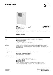
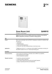
Mechanical designThe <strong>HRC3.2</strong> <strong>controller</strong> consists of a housing base, a housing cover and a printed circuitboard with connection terminals.The <strong>controller</strong> also has a tool socket, a service LED and a service pin.Cable restraintsConnectionterminalsConnection terminals for roombusConnector for service toolHousing coverConnectionterminalsHousing base6314z02Device labelOpen EnergyManagementEquipment22K4C USLISTED6314z03NoteUse of the labeling fields for handwritten entries:AdrAppl.LocKonnex addressCurrently loaded application<strong>Room</strong> numberTerminal coversSTOPCaution6314z04Owing to the intrinsic heat generated by the<strong>controller</strong>, terminal covers must not be used,as this can cause overheating.For the same reason, adequate aircirculation must be provided in the locationwhere the <strong>controller</strong> is installed.Protection from physicalcontactTo prevent accidental physical contact with relay connections carrying voltages inexcess of the SELV voltage range (U eff > 42), the device must be fitted in a housing(preferably a control panel). This enclosure must be accessible only by use of akey or tool.Alternatively, a commercially available contact guard can be used.4/12Siemens <strong>HRC3.2</strong> – <strong>Room</strong> <strong>controller</strong> CM2N6314enBuilding Technologies 01.09.2008
Connection terminalsA plug-in terminal is provided for the commissioning and service tool.All other terminals are fixed.To avoid incorrect wiring, terminals which can be connected to AC 230 V (supply andrelay outputs) are physically segregated from the other terminals. They are arranged sothat, under normal circumstances, all incoming and outgoing cables can be connectedwithout crossing.STOP CautionCable restraints must be used for the wires to terminalblocks X4 and X5 (AC 230 V).The conductors must be secured with cable ties (seediagram, right).6314z05Service LEDThe red / green service LED displays the operating status for the room <strong>controller</strong>. Theviewer see the color orange when the red and green LEDs are on at the same time.The service LED states are as follows:LED displayRed blinking: Blinkingfrequency 0.1 second on,1 second offGreen offRed blinking: Blinkingfrequency 0.1 second on,0.1 second offGreen onRed offGreen blinkingRed onGreen blinkingRed offGreen offOperating stateOperating system running; no measuring and controltask is loadedOperating system running; measuring and control taskloaded and in STOPOperating system running; measuring and control taskloaded and in RUN• The blinking frequency is the same as the cycletime for the measuring and control taskOperating system running; measuring and control taskloaded and in RUN• Addressing mode is on: The blinking frequency isthe same as the cycle time for the measuring andcontrol tasks• Address mode is off: Error• No power• ErrorResponse in the eventof a fault• If the management system or communication link fails, this will not affect localoperation• External fuses are required for the relay contacts• The <strong>controller</strong> comes with a self-resetting thermal fuse to prevent overload damage.DisposalThe device includes electrical and electronic components and must not be disposed ofas domestic waste.Current local legislation must be observed.Siemens <strong>HRC3.2</strong> – <strong>Room</strong> <strong>controller</strong> CM2N6314enBuilding Technologies 01.09.20085/12
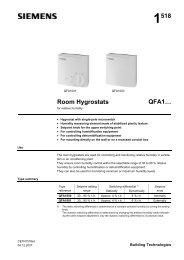
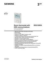
TopologyManagement system6314z01IPPSUAutomation levelSwitch/RouterKONNEX TP1N...<strong>Room</strong> <strong>controller</strong>IP/KNXN1 N2 N50PSUPower supplyPSUIP/KNXN51KONNEX TP1Field levelAC 24 VRS485R...<strong>Room</strong> devicesMMR1RnHardwareinputs/outputsValve actuatorFanBlindsLightingBellDoor openerSwitchEngineering notes• A single transformer with an output voltage of AC 24 V+/– 10% (SELV extra lowvoltage) is required for the room <strong>controller</strong> power supply.The transformer rating must be sufficient for− the room <strong>controller</strong> and associated 12 V electrical consumers (all room busdevices, DC door opener, DC signaling lamps, max. 30 VA)− all electrical loads connected to the 24 V Triac outputs• A line coupler from the KNX range is required after every 120 room <strong>controller</strong>s. Inpractice, however, a line coupler needs to be connected after approximately 50rooms, because the maximum cable length is 1000 m, and the cable length betweenrooms is typically 20 m.• The room <strong>controller</strong> must be installed in a control panel or covered enclosure, whichcan only be opened with a key or tool. Adequate air circulation must be ensured.• The relevant technical, and health and safety regulations must be observed,including local electricity company regulations applicable to connection of devices tothe electricity network.• The management level PCs must be protected with a UPS (uninterruptible powersupply).• A mechanical safety lock must be provided to allow the doors to be opened from theoutside in extreme emergencies.6/12Siemens <strong>HRC3.2</strong> – <strong>Room</strong> <strong>controller</strong> CM2N6314enBuilding Technologies 01.09.2008
AC 230 Vsupply cablesVolt-freerelay outputsAC 230 VThe sizing and fuse protection of the power supply cables depends on the total loadand on local regulations. The cables must be secured with cable restraints.• The volt-free relay outputs allow switching of loads up to AC 250 V, 4 A. The cabledimensions depend on the connected load and the local installation regulations. Thecircuits must be externally fused (≤ 10 A), as there are no internal fuses.• The cables must be secured with cable restraints.• The relay group on connector X4 may EITHER be connected to mains voltage 230 VOR to SELV 24 V. The same restriction is also valid for connector X5.Mixed operation is not allowed. However, it is possible to connect mains voltage toX4 and SELV voltage to X5 and vice versa.STOPCaution• The fans must not be connected in parallel (use cut-off relays).Mounting instructionsThe room <strong>controller</strong> can be mounted in any orientation, as follows:6314z076314z06Rail mountingThe housing base is designed forsnap-mounting on DIN rails, typeEN50022-35 x 7.5, (can be releasedwith a screwdriver).Surface mountingThere are four drill holes for screwmounting (see “Dimensions” for drillingdiagram). The housing base is fittedwith raised supports.Screws: Max. diameter 3.5 mm• The <strong>HRC3.2</strong> room <strong>controller</strong> is installed in the corridor with other installed devices,behind the plasterboard.• There must be a means of dissipating the heat generated during operation.Adequate air circulation must be ensured.• Subject to certain conditions, the <strong>HRC3.2</strong> room <strong>controller</strong> can be installed insuspended ceilings. Potential noise problems caused by the switching of relaysshould be resolved in a sample room.• As installation is the same for all types of room (e.g. single rooms or suites), it isrecommended that a sample room should be set up for each room type, incooperation with the electrical installer.• Ensure the room <strong>controller</strong> is accessible for commissioning and service work.• The card holder is intended for fixed installation in a dry, enclosed space.• Commissioning must be carried out by trained personnel onlySTOPCaution• Local safety and installation regulations must be observed!Observe the technical data for the relay outputs.7/12Siemens <strong>HRC3.2</strong> – <strong>Room</strong> <strong>controller</strong> CM2N6314enBuilding Technologies 01.09.2008
Konnex building bus(Terminal block X3)Wiring• KNX standard cable with 2 twisted pairs for connection of the Konnex gateway to allroom <strong>controller</strong>s (includes 2 spare wires)• KNX standards must be observed• No bus termination resistances are required.RS485 room bus(Terminal block X3)WiringAs a maximum, the following room devices can be connected to the room <strong>controller</strong> viathe room bus (as long as the total current does not exceed 300 mA):− 4 room operator units− 4 card readers− 4 card holdersCables: 2 twisted pairs, max. 0.5mm 2 , screened.Recommendation: There is normally no need to earth the cable screen.If the bus cable is routed parallel to mains cables over long distances, we recommendthat the bus cable should be connected, at a point near the room <strong>controller</strong>, to theprotective earth conductor.STOPCautionAdequate EMC precautions must be taken when installing the equipment.The room bus and building bus conductors must not be routed in the sameconduit as high voltage conductors.Commissioning• Before commissioning, the room <strong>controller</strong> address (KNX address) must be set,either from a laptop computer or from an operator unit (external operator/monitoringunit) connected to service socket J1.• The <strong>controller</strong> must be connected to the supply voltage for this purpose.• In the case of customer-specific applications, the customized application softwaremust be downloaded either from a laptop connected to service socket J1 or via thebuilding bus.• The application can be downloaded to individual room <strong>controller</strong>s while the bus is innormal operation.• The room <strong>controller</strong>s are already loaded with the standard application on delivery.It is then only necessary to adjust the parameters with the commissioning software.8/12Siemens <strong>HRC3.2</strong> – <strong>Room</strong> <strong>controller</strong> CM2N6314enBuilding Technologies 01.09.2008
Technical dataPower supply (externaltransformer)Working voltage:Power consumption of <strong>controller</strong> plusconnected 24 V loadsSELV AC 24 V +/–10 %, 50 / 60 HzMax. 1.25 A30 VAPorts/interfaces X1 ... X6 Screw terminalsInputs 8 digital inputs DC 12 V / 5 mA (no electrical isolation)WiringOutputsScreened twisted pairsignal conductors7 relay outputs 230 Vvolt-freeConnect conductor screen to a shield bus beforethe room <strong>controller</strong>Max. AC 250 V, max. AC 4 A4 Triac outputs 24 V Max. AC 24 V, max. 0.5 A per outputSTOPCautionTotal of all Triac outputsMax. 12 VA for all outputs4 relay outputs 230 V Max. AC 230 V / 1 A, min. DC 12 V / 0.5 W1 DC 1) output for door opener(door solenoid), non-floatingDC 12 V / 300 mA 1)short-circuit proofRS485 room bus 1)non-floatingDC 12V +10% - 15%, max. 300mA 1)short-circuit proofDC +12 V for LED indicators 1)non-floatingDC 12V +10% - 15%, max. 300mA 1)short-circuit proofSTOPCaution1) Total of all DC 12 V currents DC 12 V, max. 0. 5 AMounting DIN rail EN 50022, 37 x 7.5 mmAmbient conditions Operating temperature: 0...50ºCTransport:–30...70ºCHumidity class: F to DIN 40040Air pressure during operation: Min. 700 hPa (3000m above sea level)Air pressure during transportation: Min. 700 hPa (10, 000m above sea level)Industry standards Automatic electronic controls for IEC 60730-1household and similar useElectromagnetic Emitted interference inEN 61000-6-3compatibilityresidential areasInterference immunity inEN 61000-6-2industrial areasHousingTo EN 60 529 IP 20protection standardProtection class To EN 60 730 IIconformityMeets the requirements of: EMC 89/336/EECDirectiveLow-voltage directive73/23/EECUL/CUL approval UL/CUL 916Dimensions See also dimension diagrams 150 x 110 x 62 mmDimensions Width in DIN modular spacing units 8.5Weight excluding packaging 0.59 kgColor Body Cover: Light gray RAL 7035Base: Silver gray RAL 7001Siemens <strong>HRC3.2</strong> – <strong>Room</strong> <strong>controller</strong> CM2N6314enBuilding Technologies 01.09.20089/12
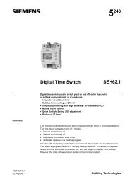
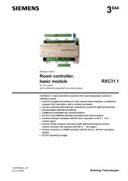
ConnectionsInterface layoutX1 X2 X3J1X4 X5 X66314z08Interfaces:X1: AC 24V +/–10% supply voltage / Triac outputsX2: Digital inputs DC 12VX3: Building bus and room bus (RS485)X4: 7 relay outputs max. AC 230 VX5: 4 relay outputs max. AC 230 VX6: 12V supply voltage for LED indicators and door opener 0J1: Service socket (RS232): 10-pin Use special service cable!Connection diagramsThe following functions are valid for the standard applicationTerminal block X1AC 24 V supplyTriac outputsPin I/O Function1 G AC 24 V supply2 G0 AC 24 V supply3 T 1 Heating valve open Max. 0.5 A, 12 VA 1)4 G05 T 2 Heating valve closed Max. 0.5 A, 12 VA 1)6 T 3 Cooling valve open Max. 0.5 A, 12 VA 1)7 G08 T 4 Cooling valve closed Max. 0.5 A, 12 VA 1)STOPCaution1)Total of all Triac outputs: Max. 12 VA for all outputse.g.: 4 outputs, each 3 VA (see information marked on device)Terminal block X2Digital inputsDC 12 V1 DI 1 "Service call" or "Make up room" button2 DI 2 "Do not disturb" button3 DI 3 "SOS / Call for Assistance" button4 DI 4 RH4 "Courtesy light" button5 GND6 DI 5 RH7 "Master light" button7 DI 6 “Guest in room” switchGuest in room = contact closed8 DI 7 Window monitoring contactWindow closed = Contact closed9 DI 8 Door monitoring contact:Door closed = Contact closed10 GND10/12Siemens <strong>HRC3.2</strong> – <strong>Room</strong> <strong>controller</strong> CM2N6314enBuilding Technologies 01.09.2008
Terminal block X3for Konnex building busand RS485 room busPin I/O Function1 A+ RS485 <strong>Room</strong> bus RS4852 B– RS485 <strong>Room</strong> bus RS4853 DC +12 V 300 mA, internal electronic fuse 2)4 GND5 CE+ Building bus (galvanically separated from <strong>controller</strong>)6 CE– Building bus (galvanically separated from <strong>controller</strong>)Terminal block X4Relay contactsMax. AC 230 V / 4A1 Fan supply voltage2 RH 1 Fan speed 13 RH 2 Fan speed 24 RH 3 Fan speed 35 Supply voltage, lighting scenario6 RH4 "Courtesy light" lighting scenario7 Supply voltage, lighting scenario8 RH5 "Light 1" lighting scenario9 Supply voltage, lighting scenario10 RH6 "Light2" lighting scenario11 Supply voltage, lighting scenario12 RH7 Master light switchSTOPCautionFans connected to the relay outputs must not be operated in parallel.For parallel operation use cut-off relays or slave room <strong>controller</strong>s.Terminal block X5Relay outputsAC 230V / 1A1 Supply voltage2 RL 1 "Service call" or "Make up room"3 RL 2 "Do not disturb"4 RL 3 "SOS / Call for Assistance" button5 RL 4 Door bellTerminal block X6Supply voltage forindicator lamps anddoor opener1 DC +12 V indicator lamps 300 mA, internal electronic fuse 2)2 GND3 DC +12 V door opener 300 mA, internal electronic fuse 2)4 GNDSTOPCaution2) Total of all DC 12 V currents: DC 12 V, max. 0.5 AService interface J1:10-pinA TxD_ESB RxD_SC 3.3VD GNDE TestF GNDG Service activeH GNDI Boot loaderJ GND Use special service cable!Siemens <strong>HRC3.2</strong> – <strong>Room</strong> <strong>controller</strong> CM2N6314enBuilding Technologies 01.09.200811/12
Service connectorGNDGNDGNDGNDRxD_SBoot loaderService activeTest3.3 VTxD_ES6314z09DimensionsDimensions in mmWithout terminalcovers35,390110623,911526314m01Drilling template1001356314z1112/12© 2006-2008 Siemens Switzerland Ltd. Subject to changeSiemens <strong>HRC3.2</strong> – <strong>Room</strong> <strong>controller</strong> CM2N6314enBuilding Technologies 01.09.2008