2724 Zone Room Unit QAW810
2724 Zone Room Unit QAW810
2724 Zone Room Unit QAW810

You also want an ePaper? Increase the reach of your titles
YUMPU automatically turns print PDFs into web optimized ePapers that Google loves.
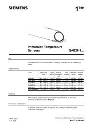
2 724<strong>Zone</strong> <strong>Room</strong> <strong>Unit</strong>for RRV817 Control System<strong>QAW810</strong>Digital zone control unit as an installer and end-user interface for use with theRRV817 temperature controller for underfloor heating systemsUsePlantsApplication<strong>Room</strong> unit in combination with the RRV817 temperature controller for underfloor heatingsystems in:• Apartments• Detached houses• Light commercial applications• Conjunction with district heating schemes or local heat sources1 <strong>QAW810</strong> per zone 2 to 7, in conjunction with the RRV817 temperature controller andthe QAX810 (master) room unit, in water-based heating plant.FunctionsPrimary functionsOperator functions• <strong>Zone</strong> control and monitoring in combination with an RRV817 plus QAX810• <strong>Zone</strong> addressing by the installer• <strong>Room</strong> temperature acquisition• Local zone control and monitoring• Temporary setpoint adjustment• <strong>Zone</strong> comfort, energy saving, auto-timer and standby selection• Display of operating mode and zone temperatureAP1N<strong>2724</strong>en28.08.2007Building TechnologiesHVAC Products
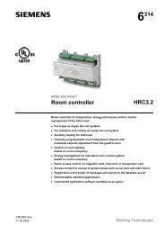
Type summaryType reference Description Compatible with*<strong>QAW810</strong> <strong>Zone</strong> room unit • Master room unit QAX810• Temperature controller RRV817* Not suited for use with the Desigo RX range of controllersProduct documentationDocumentData sheetMounting InstructionsOperating InstructionsDocument numberN<strong>2724</strong>M2723B2723Mechanical designType of unitThe <strong>QAW810</strong> is the end-user zone MMI for RRV817 controllers.T The unit consists of the following components:• <strong>Room</strong> unit with integrated electronics and operating elements• Built-in temperature sensor• Base with connection terminals for wall mounting• Operator interface buttonsOperating elements12453<strong>2724</strong>P011 LED for zone valve control status (heat output status at the RRV817)2 LCD with backlight for control and monitoring of operating modes,setpoints, zone conditions, etc.3 Operating mode selection – comfort, energy saving and auto timer4 Setpoint adjustment5 <strong>Zone</strong> standbyLCD1C<strong>2724</strong>Z01OFF3456ZONE2123456Actual temperature<strong>Zone</strong> indication<strong>Zone</strong> OFFComfort modeEnergy saving modeAuto timer mode2/6Siemens <strong>Zone</strong> <strong>Room</strong> <strong>Unit</strong> <strong>QAW810</strong> AP1N<strong>2724</strong>enBuilding Technologies 28.08.2007
Mounting and installation notesThe <strong>QAW810</strong> should be mounted in a location where the air temperature can be acquiredas accurately as possible without getting adversely affected by direct solar radiationor other heating or cooling sources..• Mounting height is about 1.5 m above the floor.• The unit can be fitted to a recessed conduit box.• The specified ambient conditions must be observed.• Only authorized staff may remove the <strong>QAW810</strong> unit from its base.• Do not mount in recesses, shelves, or behind curtains or doors.• Refer to the Mounting Instructions included in the packaging box.When mounting the unit, fit the base first and then make the electrical connections. Toavoid damage during construction work, install the <strong>QAW810</strong> only when all constructionwork is completed. The <strong>QAW810</strong> must be mounted on a flat surface and in compliancewith local regulations.Local regulations for installation must be observedSTOP Note!The room unit is not protected against connection to AC 230 V!Commissioning notesResponse on startupSensor calibrationCommissioningWhen powering up, the <strong>QAW810</strong> will display all LCD symbols for approximately 2 seconds.The LCD will then revert to normal display. There will be a delay before operationcommences due to polling of all values.Generally, there is no need to calibrate the sensor. However, the room temperaturedisplayed can be calibrated if there is a deviation from the actual temperature measuredby a certified thermometer.The calibration function can be accessed by pressing the and buttons simultaneouslyfor 2 seconds. The displayed value can then be readjusted, using the same buttons,in 0.5 K increments. The readjustment range is ±2 K.Initial installation-specific application setup is made by the setting of DIP switch positionson the RRV817 controller. DIP switches are located at the top of the RRV817controller’s PCB.The <strong>QAW810</strong> features DIP switches for zone addressing. In addition to the QAX810master zone, using the <strong>QAW810</strong>, up to 6 further zones can be connected to theRRV817 controller. The QAX810 master room unit is always zone 1 (automatic - noaddress setting necessary).Siemens <strong>Zone</strong> <strong>Room</strong> <strong>Unit</strong> <strong>QAW810</strong> AP1N<strong>2724</strong>enBuilding Technologies 28.08.20073/6
DIP switchesDIP switches at the rear of the <strong>QAW810</strong>They allow setting the address in caseswhere several room units are connectedto 1 RRV817 controller.The room units are delivered with defaultpositions = zone 2.DIP switch Function S1 S2 S3 <strong>Room</strong>1…3 <strong>Zone</strong> identity OFF ON OFF 2ON ON OFF 3OFF OFF ON 4ON OFF ON 5OFF ON ON 6ON ON ON 7BOLD = default settingTechnical dataInterfaces (S+, SG) HCC bus proprietary protocolBus power supply voltageDC 12 V, +10, –15% (supplyRRV817 controller)Baud rate9.6 kbit/s<strong>Room</strong> unit power consumption2 VAPermissible cable lengthsFor bus communicationA ≥0.5 mm²A ≥1 mm²Type of cableNote:Twisted pair (unshielded) is recommended for enhanced immunityto external electromagnetic interference, e.g. in the vicinityof radio transmitters or variable speed drivesmax. 60 mmax. 100 m2-wire standard installation cable(unshielded)Electrical connections(HB+, HB–)Connection terminalsFor wiresscrew terminals0.6 mm dia. … 2.5 mm 2Degrees of protection Degree of protection of housing to IEC 60 529 IP 30Safety class to EN 60 730device suited for use with equipmentof safety class IIEnvironmental conditionsOperation toClimate conditionsTemperature (housing and electronics)HumidityMechanical conditionsTransport toClimate conditionsTemperatureHumidityMechanical conditionIEC 721-3-3class 3K50…50 °C5…95 % r. h. (non-condensing)class 3M2IEC 721-3-2class 2K3–25…+70 °C
Rated surge voltageSoftware class4000 VAMaterials and colors Top housing Polycarbonate, RAL 9003 (signalwhite)Bottom housing and base platePolycarbonate, RAL 7035 (lightgrey)Packagingcorrugated cardboardNorms and standardsProduct safetyAutomatic electrical controls for household andsimilar useEN 60 730-1Special requirements for temperature sensingcontrolsEN 60 730-2-9Electromagnetic compatibilityImmunity domestic section, light industry EN 61 000-6-1Emissions domestic section, light industry EN 61 000-6-3-conformityEMC directiveLow-voltage directiveN474 conformity toAustralian EMC frameworkRadio interference emission Standard89/336/EEC73/23/EECRadio Communication Act 1992AS/NZS 4251.1<strong>Room</strong> temperature Measuring range 0…49 °Cmeasurement Setpoint range 5…35 °CAccuracy at 20 °Cmax. ±0.5 KTemperature calibration rangemax. ±3.0 K in increments of 0.5 K<strong>Room</strong> temperature display resolution0.5 KWeight Excluding packaging approx. 0.1 kgNotesProduct liability• The products may only be used in building services plant and applications as describedabove.• When using the products, all requirements specified under ”Technical data” must beobserved.• Local regulations for electrical installations must be complied with.Connection diagram<strong>2724</strong>A01S+SGN1S+SGA1S+SGA2N1 RRV817 temperature controllerN2 QAX810 master room unitN3 <strong>QAW810</strong> zone room unitS+, SG Communication busConnected to other<strong>QAW810</strong> zone roomunitsSiemens <strong>Zone</strong> <strong>Room</strong> <strong>Unit</strong> <strong>QAW810</strong> AP1N<strong>2724</strong>enBuilding Technologies 28.08.20075/6
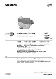
DimensionsController3031M011199623,8Base428 2830283528411,8112,326 3089,453035M02Dimensions in mm6/6©2005 Siemens Switzerland LtdSubject to alterationSiemens <strong>Zone</strong> <strong>Room</strong> <strong>Unit</strong> <strong>QAW810</strong> AP1N<strong>2724</strong>enBuilding Technologies 28.08.2007