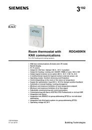
RDG100KN Room thermostat with KNX communications
RDG100KN Room thermostat with KNX communications
RDG100KN Room thermostat with KNX communications
- No tags were found...

You also want an ePaper? Increase the reach of your titles
YUMPU automatically turns print PDFs into web optimized ePapers that Google loves.
UseThe <strong>RDG100KN</strong> room <strong>thermostat</strong> is designed for use <strong>with</strong> the following types ofsystem:Fan coil units via ON/OFF or modulating control outputs: 2-pipe system 2-pipe system <strong>with</strong> electric heater 2-pipe system and radiator / floor heating 4-pipe system 4-pipe system <strong>with</strong> electric heater 2-stage heating or cooling systemChilled / heated ceilings (or radiators) via ON/OFF or modulating controloutputs: Chilled / heated ceiling Chilled / heated ceiling <strong>with</strong> electric heater Chilled / heated ceiling and radiator / floor heating Chilled / heated ceiling, 2-stage cooling or heatingThe room <strong>thermostat</strong>s are delivered <strong>with</strong> a fixed set of applications.The relevant application is selected and activated during commissioning using oneof the following tools: Synco ACS ETS3 Professional (planned) Local DIP switch and HMIFunctions <strong>Room</strong> temperature control via built-in temperature sensor or external roomtemperature / return air temperature sensor Changeover between heating and cooling mode (automatic via local sensor orbus, or manual) Selection of applications via DIP switches or commissioning tool (ACS700,ETS3 Professional) Select operating mode via operating mode button on the <strong>thermostat</strong> Temporary Comfort mode extension Single speed or 3-speed fan control (automatic or manual) Display of current room temperature or setpoint in °C and/or °F Minimum and maximum limitation of room temperature setpoint Button lock (automatic or manual) 3 multifunctional inputs, freely selectable for: Operating mode switchover contact (keycard, window contact, etc.) Sensor for automatic heating / cooling changeover External room temperature or return air temperature sensor Dewpoint sensor Electric heater enable Fault input Monitor input for temperature sensor or switch status Advanced fan control function, e.g. fan kick, fan start, selectable fan operation(enable, disable or depending on heating or cooling mode) Purge function together <strong>with</strong> 2-port valve in a 2-pipe changeover system Reminder to clean fan filters Floor heating temperature limitation Reload factory settings for commissioning and control parameters2 / 14Siemens <strong>RDG100KN</strong> <strong>Room</strong> <strong>thermostat</strong> <strong>with</strong> <strong>KNX</strong> <strong>communications</strong> CE1N3191enBuilding Technologies 01 Jun 2010
<strong>KNX</strong> bus (terminals CE+ and CE-) for communication <strong>with</strong> Synco or <strong>KNX</strong>compatible devices Display of outside temperature or time of day via <strong>KNX</strong> bus Time scheduling and central control of setpoints via <strong>KNX</strong> bus With a Synco RMB7xx controller, the energy demand signal of the <strong>thermostat</strong> isused to optimize energy supply.ApplicationsThe <strong>thermostat</strong>s support the following applications, which can be configured usingthe DIP-switches at the rear of the unit or a commissioning tool.All DIP switches need to be set to OFF (remote configuration, factory setting) toselect an application via commissioning tool.ApplicationDIP switchesRemote configurationvia commissioning tool (factory setting) Synco ACS ETS3 professional (planned)Heating or cooling 2-pipe fan coil unit Chilled / heated ceilingB2TT(B1)ONOFF1 2 3 4 5ONOFF1 2 3 4 5Y1M1T(B1)Heating or cooling <strong>with</strong> electric heater 2-pipe fan coil unit and electric heater Chilled / heated ceiling and el. heaterONOFF1 2 3 4 5NoteUse P46 / P47 to change output from ON/OFF (factory setting) to PWMUse DIP switches 4 and 5 to change output from ON/OFF to 3-positionSiemens <strong>RDG100KN</strong> <strong>Room</strong> <strong>thermostat</strong> <strong>with</strong> <strong>KNX</strong> <strong>communications</strong> CE1N3191enBuilding Technologies 01 Jun 20103 / 14
Heating or cooling and radiator / floorheating 2-pipe fan coil unit and radiator Chilled / heated ceiling and radiatorB2TT(B1)ONOFF1 2 3 4 5Y1M1T(B1)YRHeating and cooling 4-pipe fan coil unit Chilled ceiling and radiatorONOFF1 2 3 4 5Y2T(B1)Y1M1T(B1)Heating and cooling and electric heater 4-pipe fan coil unit and electric heaterONOFF1 2 3 4 52-stage heating or cooling 2-stage fan coil unit 2-stage chilled / heated ceilingTB2ONOFFY2 1 2 3 4 5TY1(B1)M1T(B1)NoteUse P46 / P47 to change output from ON/OFF (factory setting) to PWMUse DIP switches 4 and 5 to change output from ON/OFF to 3-position4 / 14Siemens <strong>RDG100KN</strong> <strong>Room</strong> <strong>thermostat</strong> <strong>with</strong> <strong>KNX</strong> <strong>communications</strong> CE1N3191enBuilding Technologies 01 Jun 2010
Type summaryProduct no. Stock no. FeaturesOperatingvoltageNumber of control outputsBacklitLCDON/OFF PWM 3-pos.<strong>RDG100KN</strong> S55770-T163 AC 230 V 3 1) 2 1) 2 1) 1) ON/OFF, PWM or 3-position (triac outputs)Ordering When ordering, indicate both product number / stock number and name: E.g. <strong>RDG100KN</strong> / S55770-T163 room <strong>thermostat</strong> Order valve actuators separately.Equipment combinationsDescriptionProduct no.DatasheetCable temperature sensor QAH11.1 1840<strong>Room</strong> temperature sensor QAA32 1747On / off actuatorsOn / off and PWMactuators *)3-position actuatorsCondensation detector / extensionmoduleQXA2000 /QXA2001 /AQX20001542Electromotoric ON/OFF actuator SFA21... 4863Electromotoric ON/OFF valve andactuator(only available in AP, UAE, SA and IN)Zone valve actuator(only available in AP, UAE, SA and IN)MVI… / MXI… 4867SUA… 4830Thermal actuator (for radiator valves) STA21... 4893Thermal actuator(for small valves 2.5 mm)Electrical actuator, 3-position(for radiator valves)Electrical actuator, 3-position(for small valves 2.5 mm)Electrical actuator, 3-position(for small valves 5.5 mm)Electrical actuator, 3-position(for small valve 5,5 mm)STP21... 4878SSA31... 4893SSP31… 4864SSB31... 4891SSD31... 4861*) With PWM control, it is not possible to ensure exact parallel running of more than one thermal actuator.If several fan-coil systems are controlled by the same room <strong>thermostat</strong>, preference should be given tomotorized actuators <strong>with</strong> ON/OFF or 3-position control.Siemens <strong>RDG100KN</strong> <strong>Room</strong> <strong>thermostat</strong> <strong>with</strong> <strong>KNX</strong> <strong>communications</strong> CE1N3191enBuilding Technologies 01 Jun 20105 / 14
AccessoriesDescriptionProduct no. / Datastock no. sheetChangeover mounting kit (50 pcs / package) ARG86.3 N3009Adapter plate 120 x 120 mm for 4“ x 4“N3009ARG70conduit boxesAdapter plate 112 x 130 mm for surface wiring ARG70.2 N3009<strong>KNX</strong> Power supply 160 mA (Siemens BT LV) 5WG1 125-1AB01 --<strong>KNX</strong> Power supply 320 mA (Siemens BT LV) 5WG1 125-1AB11 --<strong>KNX</strong> Power supply 640 mA (Siemens BT LV) 5WG1 125-1AB21 --Mechanical designThe room <strong>thermostat</strong> consists of 2 parts: Plastic housing <strong>with</strong> electronics, operating elements and room temperaturesensor Mounting plate <strong>with</strong> the screw terminalsThe housing engages in the mounting plate and is secured <strong>with</strong> 2 screws.Operation and settings1321) Operating mode button / Esc2) Fan mode button / Ok3) Rotary knob to adjust setpoints andparameters6 / 14Siemens <strong>RDG100KN</strong> <strong>Room</strong> <strong>thermostat</strong> <strong>with</strong> <strong>KNX</strong> <strong>communications</strong> CE1N3191enBuilding Technologies 01 Jun 2010
Display# Symbol Description # Symbol Description1 Heating mode 14 Automatic fan2Heating mode,electric heater active15 Manual fan3 Cooling mode Fan speed 14 Comfort 16 Fan speedFan speed 25 EconomyFan speed 36Auto Timer mode according toschedule (via <strong>KNX</strong>)17Degrees CelsiusDegrees Fahrenheit8 Protection mode 18 Digits for room temperature and setpoint display9 Escape 19 Button lock10Additional user information, like outdoortemperature or time of dayfrom <strong>KNX</strong> bus. Selectable viaparameters20 Condensation in room (dewpoint sensor active)12Morning: 12-hour formatAfternoon: 12-hour format21Weekday 1…7 from <strong>KNX</strong> bus1 = Monday / 7 = Sunday13 Confirmation of parameters 22 Fault23Temporary timer function; visible whenoperating mode is temporarily extended(extended presence or absence)24 Indicates that room temperature is displayedSiemens <strong>RDG100KN</strong> <strong>Room</strong> <strong>thermostat</strong> <strong>with</strong> <strong>KNX</strong> <strong>communications</strong> CE1N3191enBuilding Technologies 01 Jun 20107 / 14
Engineering notesSee the "Reference documentation", page 12 for information on how to engineerthe <strong>KNX</strong> bus (topology, bus repeaters, etc.) and how to select and dimensionconnecting cables for supply voltage and field devices.Mounting and installationDo not mount on a wall in niches or bookshelves, behind curtains, above or nearheat sources, or exposed to direct solar radiation. Mount about 1.5 m above thefloor.Mounting Mount the room <strong>thermostat</strong> on a clean, dry indoor place <strong>with</strong>out direct airflowfrom a heating / cooling device, and not exposed to drips or splash water.WiringSee the mounting instructions M3191 enclosed <strong>with</strong> the <strong>thermostat</strong>. Comply <strong>with</strong> local regulations to wire, fuse and earth the <strong>thermostat</strong>. Properly size the cables to the <strong>thermostat</strong>, fan and valve actuators for AC 230 Vmains voltage. Use only valve actuators rated for AC 230 V. The AC 230 V mains supply line must have an external fuse or circuit breaker<strong>with</strong> a rated current of no more than 10 A. Isolate the cables of input D1-GND for 230 V if the conduit box carries AC 230 Vmains voltage. X1-M,X2-M or D1-GND: several switches (e.g. summer/winter switch) may beconnected in parallel. Consider overall maximum contact sensing current forswitch rating. Inputs X1-M and X2-M carry mains potential.Sensor cables must be suited for AC 230 V mains voltage Isolate the cables of <strong>KNX</strong> communication input CE+ / CE- for 230 V if the conduitbox carries AC 230 V mains voltage. No cables provided <strong>with</strong> a metal sheath. Disconnect from supply before removing from the mounting plate.8 / 14Siemens <strong>RDG100KN</strong> <strong>Room</strong> <strong>thermostat</strong> <strong>with</strong> <strong>KNX</strong> <strong>communications</strong> CE1N3191enBuilding Technologies 01 Jun 2010
Commissioning notesApplicationsThe room <strong>thermostat</strong>s are delivered <strong>with</strong> a fixed set of applications.Select and activate the relevant application during commissioning using one of thefollowing tools: Local DIP switch and HMI Synco ACS ETS3 Professional (planned)Set the DIP switches before snapping the <strong>thermostat</strong> to the mounting plate, if youwant to select an application via DIP switches.All DIP switches need to be set to “OFF” ("remote configuration"), if you want toselect an application via commissioning tool.After power is applied, the <strong>thermostat</strong> resets and all LCD segments flash, indicatingthat the reset was correct. After the reset, which takes about 3 seconds, the<strong>thermostat</strong> is ready for commissioning by qualified HVAC staff.If all DIP switches are OFF, the display reads "NO APPL" to indicate thatapplication commissioning via a tool is required.NoteEach time the application is changed, the <strong>thermostat</strong> reloads the factory setting forall control parameters, except for <strong>KNX</strong> device and zone addresses!Connect toolConnect the Synco ACS or ETS3 Professional tools to the <strong>KNX</strong> bus cable at anypoint for commissioning:<strong>KNX</strong>LX1 M X2D1 GNDCE+CE-<strong>KNX</strong>SiemensN148 /UP146 /UP152<strong>KNX</strong>SiemensOCI700N Q1 Q2 Q3 Y1 Y2Y3Y4N1V24USBRS232ETSETS / ACS3191A03ACS and ETS3 require an interface: RS232 <strong>KNX</strong> interface (e.g. Siemens N148 / UP146 / UP152) OCI700 USB- <strong>KNX</strong> interfaceNoteAn external <strong>KNX</strong> bus power supply is required if an <strong>RDG100KN</strong> is connecteddirectly to a tool (ACS or ETS3) via <strong>KNX</strong> interface.Siemens <strong>RDG100KN</strong> <strong>Room</strong> <strong>thermostat</strong> <strong>with</strong> <strong>KNX</strong> <strong>communications</strong> CE1N3191enBuilding Technologies 01 Jun 20109 / 14
Control parametersThe <strong>thermostat</strong>'s control parameters can be set to ensure optimum performance ofthe entire system (see basic documentation P3191).The parameters can be adjusted using Local HMI Synco ACS ETS3 Professional (planned)Control sequenceCalibrate sensorSetpoint and rangelimitation The control sequence may need to be set via parameter P01 depending on theapplication. The factory setting is as follows:Application2-pipe and chilled / heated ceiling, and 2-stage4-pipe, chilled ceiling and radiatorFactory setting P011 = Cooling only4 = Heating and cooling Recalibrate the temperature sensor if the room temperature displayed on the<strong>thermostat</strong> does not match the room temperature measured (after min. 1 hour ofoperation). To do this, change parameter P05. We recommend to review the setpoints and setpoint ranges (parametersP08…P12) and change them as needed to achieve maximum comfort and saveenergy.Programming modeThe programming mode helps identify the <strong>thermostat</strong> in the <strong>KNX</strong> network duringcommissioning.Press the left and right buttons simultaneously for 6 sec to activate programmingmode, which is indicated on the display <strong>with</strong> "PrOg".Programming mode remains active until <strong>thermostat</strong> identification is complete.Assign <strong>KNX</strong> groupaddressesUse ETS3 Professional to assign the <strong>KNX</strong> group addresses of the RDG communicationobjects.<strong>KNX</strong> serial numberEach device has a unique <strong>KNX</strong> serial number inside the plastic housing.An additional sticker <strong>with</strong> the same <strong>KNX</strong> serial number is enclosed in the packagingbox. This sticker is intended for installers for documentation purposes.DisposalThis device is classified as waste electronic equipment under European Directive2002/96/EC (WEEE) and may not be disposed of as unsorted municipal waste.Adhere to all relevant national laws.Regarding disposal, use the systems setup for collecting electronic waste.Observe all local and applicable laws.10 / 14Siemens <strong>RDG100KN</strong> <strong>Room</strong> <strong>thermostat</strong> <strong>with</strong> <strong>KNX</strong> <strong>communications</strong> CE1N3191enBuilding Technologies 01 Jun 2010
Technical dataPower supplyOutputsInputs<strong>KNX</strong> busOperational dataOperating voltage AC 230 V +10/-15%Frequency50/60 HzPower consumptionMax. 15 VA / 2 WFan control Q1, Q2, Q3-NAC 230 VRatingMax. 5(4) AControl outputsSolid state (Triac)Y1, Y2, Y3, Y4-NAC 230 V, max. 1 AMultifunctional inputsX1-M / X2-MTemperature sensor inputTypeQAH11.1 (NTC)Digital inputOperating actionSelectable (NO/NC)Contact sensingDC 0…5 V, max. 5 mAInsulation against mainsN/A, mains potentialD1-GNDOperating actionSelectable (NO/NC)Contact sensingSELV DC 6…15 V, 3…6 mAInsulation against mains3.75 kV, reinforced insulationFunction of inputsExternal temperature sensor, heating/coolingchangeover sensor, operating mode switchovercontact, dewpoint monitor contact, enable electricheater contact, fault contact, monitoring inputInterface typeSelectableX1: P38X2: P40D1: P42<strong>KNX</strong>, TP1-64(electrically isolated)Bus current20 mABus topology: See <strong>KNX</strong> manual (reference documentation, see below)Switching differential, adjustableHeating mode(P30) 2 K (0.5…6 K)Cooling mode(P31) 1 K (0.5…6 K)Setpoint setting and setpoint rangeComfort mode(P08) 21 °C (5…40 °C)Economy(P11-P12) 15 °C/30 °C (OFF, 5…40 °C)Protection(P65-P66) 8 °C/OFF (OFF, 5…40 °C)Multifunctional inputs X1 / X2 / D1Input X1 default value(P38)Input X2 default valueInput D1 default valueBuilt-in room temperature sensorMeasuring rangeAccuracy at 25 °CTemperature calibration rangeSettings and display resolutionSetpointsCurrent temperature value displayed(P40)(P42)Selectable (0...8)1 (Ext. temperature sensor,room or return air)0 (no function)3 (Operating mode switchover)0…49 °C< ± 0.5 K± 3.0 K0.5 °C0.5 °C11 / 14Siemens <strong>RDG100KN</strong> <strong>Room</strong> <strong>thermostat</strong> <strong>with</strong> <strong>KNX</strong> <strong>communications</strong> CE1N3191enBuilding Technologies 01 Jun 2010
Environmental conditionsStandards and directivesOperationClimatic conditionsTemperatureHumidityTransportClimatic conditionsTemperatureHumidityMechanical conditionsStorageClimatic conditionsTemperatureHumidityIEC 721-3-3Class 3K50…50 °C
Connection terminalsL X1 M X2SELVD1 GND CE+ CE -N Q1 Q2 Q3 Y1 Y2 Y3 Y43191A01L, N Operating voltage AC 230 VX1, X2 Multifunctional input for temperature sensor(e.g. QAH11.1) or potential-free switchFactory setting:– X1 = External temperature sensor– X2 = No function(function can be selected via parameters P38 / P40).M Measuring neutral for sensors and switchesD1, GND Multifunctional input for potential-free switchFactory setting: Operating mode switchover contact(function can be selected via parameter P42).Q1 Control output fan speed “low” AC 230 VQ2 Control output fan speed “medium” AC 230 VQ3 Control output fan speed “high” AC 230 VY1…Y4 Control output “Valve” AC 230 V(NO contact, for normally closed valves),output for electric heater via external relayCE+ <strong>KNX</strong> data +CE- <strong>KNX</strong> data –Connection diagramsApplication 2-pipe 2-pipe andradiator 4-pipe 2-stage 2-pipeand electricheater 4-pipeand electricheaterLF 10 AAC 230 VNLN Q1 Q2 Q3M1S1B1I II IIIX1 M X25(2)Amax.S2B2Y11Amax.S3D1 GNDCE+Y1 Y2 Y3 Y4Y1Y1Y1KKY2Y2CE-<strong>KNX</strong>E1E13191A12N1N1 <strong>Room</strong> <strong>thermostat</strong> <strong>RDG100KN</strong>M1 1- or 3-speed fanV1, V2 Valve actuators:ON/OFF or PWM, 3-position,heating, cooling, radiator, heating / cooling,1st or 2nd stageE1 Electric heaterK RelayF External fuseS1, S2 Switch (keycard, window contact, presencedetector, etc.)S3 Switch at SELV input(keycard, window contact)B1, B2 Temperature sensor (return air temperature,external room temperature,changeover sensor, etc.)CE+ <strong>KNX</strong> data +CE– <strong>KNX</strong> data –13 / 14Siemens <strong>RDG100KN</strong> <strong>Room</strong> <strong>thermostat</strong> <strong>with</strong> <strong>KNX</strong> <strong>communications</strong> CE1N3191enBuilding Technologies 01 Jun 2010
DimensionsDimensions in mm4.09.028.328.34.028.328.3128.028.316.027.793.028.530.828.2 27.814 / 14© 2010 Siemens Switzerland Ltd Subject to changeSiemens <strong>RDG100KN</strong> <strong>Room</strong> <strong>thermostat</strong> <strong>with</strong> <strong>KNX</strong> <strong>communications</strong> CE1N3191enBuilding Technologies 01 Jun 2010