RDG400KN Room thermostat with KNX communications - Ifs Store
RDG400KN Room thermostat with KNX communications - Ifs Store
RDG400KN Room thermostat with KNX communications - Ifs Store

Create successful ePaper yourself
Turn your PDF publications into a flip-book with our unique Google optimized e-Paper software.
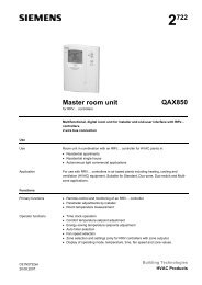
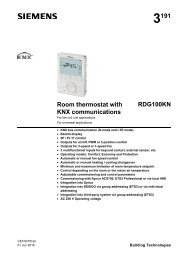
s3 192<strong>Room</strong> <strong>thermostat</strong> <strong>with</strong><strong>KNX</strong> <strong>communications</strong>For VAV heating and cooling systems<strong>RDG400KN</strong> <strong>KNX</strong> bus <strong>communications</strong> (S-mode and LTE mode) Backlit display PI / P control Output for VAV box / damper: DC 0…10 V / 3-position Output for heating / cooling coil: ON/OFF, PWM or 3-pos / DC 0..10V Output signal inversion as an option (DC 0...10 V DC 10...0 V) 2 multifunctional inputs for keycard contact, external sensor, etc Operating modes: Comfort, Economy and Protection Control depending on the room or the return air temperature Supply fan optimization: Input DC 0...10 V for damper position feedback Automatic or manual heating / cooling changeover Minimum and maximum limitation of room temperature setpoint Minimum and maximum limitation of air flow signal Adjustable commissioning and control parameters Commissioning <strong>with</strong> Synco ACS700, ETS3 Professional or via local HMI Integration into Synco Integration into DESIGO via group addressing (ETS3) or via individualaddressing Integration into third-party system via group addressing (ETS3) Operating voltage AC 24 VCE1N3192en01 Jun 2010 Building Technologies
UseThe <strong>RDG400KN</strong> room <strong>thermostat</strong> is designed for the following types of system:VAV systems via ON/OFF or modulating control outputs: Single-duct system Single-duct system <strong>with</strong> electric heater Single-duct system and radiator / floor heating Single-duct system <strong>with</strong> heating / cooling coilThe room <strong>thermostat</strong> is delivered <strong>with</strong> a fixed set of applications.The relevant application is selected and activated during commissioning using oneof the following tools: Synco ACS ETS3 Professional (planned) Local DIP switch and HMIFunctions <strong>Room</strong> temperature control via built-in temperature sensor or external roomtemperature / return air temperature sensor Changeover between heating and cooling mode (automatic via local sensor orbus, or manual) Selection of applications via DIP switches or commissioning tool (ACS700,ETS3 Professional) Select operating mode via operating mode button on the <strong>thermostat</strong> Temporary Comfort mode extension Display of current room temperature or setpoint in °C and/or °F Minimum and maximum limitation of room temperature setpoint Minimum and maximum limitation of air flow signal Button lock (automatic or manual) 2 multifunctional inputs, freely selectable for: Operating mode switchover contact (keycard, window contact, etc.) Changeover sensor for automatic heating / cooling mode External room temperature or return air temperature sensor Dewpoint sensor Electric heater enable Faults Monitor input for temperature sensor or switch status One DC 0...10 V input for damper position feedback Floor heating temperature limit Reload factory settings for commissioning and control parameters <strong>KNX</strong> bus (terminals CE+ and CE-) for communication <strong>with</strong> Synco or <strong>KNX</strong>compatible devices Display of outside temperature or time of day via <strong>KNX</strong> bus Time scheduling and central control of setpoints via <strong>KNX</strong> bus A RMB7xx / RMU7xx controller (signal exchange over <strong>KNX</strong>) uses: the air demand signal of the <strong>thermostat</strong> to optimize supply air temperature. the energy demand signals of the heating / cooling device to optimize energysupply. the damper position feedback (DC 0...10 V) to optimize supply fan speed.2 / 14Siemens <strong>RDG400KN</strong> <strong>Room</strong> <strong>thermostat</strong> <strong>with</strong> <strong>KNX</strong> <strong>communications</strong> CE1N3192enBuilding Technologies 01 Jun 2010
ApplicationsThe <strong>thermostat</strong> supports the following applications, which can be configured usingthe DIP switches at the rear of the unit or a commissioning tool.DIP switches 1...3 need to be set to OFF (remote configuration, factory setting) toselect an application via commissioning tool.ApplicationRemote configurationvia commissioning tool (factory setting) Synco ACS ETS3 professional (planned)Single-duct DC 0…10 V damper actuator (P47 = 0) 3-position damper actuator (P47 = 1)YVVMTB13192S07DIP switchesONOFF1 2 3 4 5ONOFF1 2 3 4 5Single-duct <strong>with</strong> electric heater DC 0…10 V damper actuator and ON/OFF,PWM or 3-position electric heater (P47 = 0) 3-position damper actuator andDC 0…10 V electric heater (P47 = 1)YVVMYETB13192S08ONOFF1 2 3 4 5Single-duct and radiator / floor heating DC 0…10 V damper actuator and ON/OFF,PWM or 3-position radiator (P47 = 0) 3-position damper actuator andDC 0…10 V radiator (P47 = 1)YVVMTB13192S09ONOFF1 2 3 4 5YRSingle-duct heating and cooling coil DC 0…10 V damper actuator and ON/OFF,PWM or 3-position heating and cooling(P47 = 0) 3-position damper actuator andDC 0…10 V heating and cooling(P47 = 1)YVVMY1T(B1)T(B1)3192S11ONOFF1 2 3 4 5NoteUse P47 to change damper output from DC 0...10 V (factory setting) to 3-positionUse P46 to change valve output from ON/OFF (factory setting) to PWMUse DIP switch 5 to change valve output from ON/OFF to 3-positionSiemens <strong>RDG400KN</strong> <strong>Room</strong> <strong>thermostat</strong> <strong>with</strong> <strong>KNX</strong> <strong>communications</strong> CE1N3192enBuilding Technologies 01 Jun 20103 / 14
Type summaryProduct no.StocknumberFeaturesOperatingvoltageNumber of control outputsBacklitLCDON/OFF PWM 3-pos DC 0…10 V<strong>RDG400KN</strong> S55770-T165 AC 24 V 1 1) 1 1) 1 1) 1 1) ON/OFF, 3-position or PWMOrdering When ordering, indicate both product number / stock number and name: E.g. <strong>RDG400KN</strong> / S55770-T165 room <strong>thermostat</strong> Order valve actuators separately.Equipment combinationsType of unitProduct no.DatasheetCable temperature sensor QAH11.1 1840<strong>Room</strong> temperature sensor QAA32 1747DC 0..10 V actuatorsCondensation detector / Supply unitElectrical actuator, DC 0..10 V(for radiator valve)Electrical actuator, DC 0..10 V(for 2 and 3 port valves / V…P45)Electrical actuator, DC 0..10 V(for small valve 2,5 mm)Electrical actuator, DC 0..10 V(for small valves 5.5 mm)Electrical actuator, DC 0..10 V(for Combi-valve VPI45)Thermal actuator, DC 0..10 V(for small valves and radiatorvalves)Electromotoric actuator, DC 0..10V(for valves 5.5 mm)QXA2000 /QXA2001 /AQX20001542SSA61... 4893SSC61… 4895SSP61… 4864SSB61... 4891SSD61... 4861STS61 4880SQS65… 45734 / 14Siemens <strong>RDG400KN</strong> <strong>Room</strong> <strong>thermostat</strong> <strong>with</strong> <strong>KNX</strong> <strong>communications</strong> CE1N3192enBuilding Technologies 01 Jun 2010
Type of unitProduct no.DatasheetGQD161… 4605GDB161…GLB161…4634DC 0…10 V damper actuatorGMA161… 4614GEB161… 4621GCA161… 4613VAV compact controllerGBB161…GIB161…GDB181.1E/3GLB181.1E/346263544ON/OFF actuatorsAC 24 VElectromotoric ON/OFF valve andactuator(only available in AP, UAE, SA and IN)MVI…/MXI… 4867Electromotoric ON/OFF actuator SFA71... 4863ON/OFF / PWMactuators AC 24 V *)3-position actuatorsAC 24 VThermal actuator (for radiator valve) STA71... 4877Thermal actuator(for small valves 2.5 mm)Electrical actuator, 3-position(for radiator valve)STP71... 4878SSA81... 4893Electrical actuator, 3-position(for small valve 2,5 mm)Electrical actuator, 3-position(for small valve 5,5 mm)Electrical actuator, 3-position(for Combi-valve VPI45)Electromotoric actuator, 3-position(for valves 5.5 mm)SSP81… 4864SSB81... 4891SSD81... 4861SQS85… 4573*) With PWM control, it is not possible to ensure exact parallel running of more than one thermal actuator. <strong>Ifs</strong>everal actuators are controlled by the same room <strong>thermostat</strong>, preference should be given to motorizedactuators <strong>with</strong> ON/OFF or 3-position control.Siemens <strong>RDG400KN</strong> <strong>Room</strong> <strong>thermostat</strong> <strong>with</strong> <strong>KNX</strong> <strong>communications</strong> CE1N3192enBuilding Technologies 01 Jun 20105 / 14
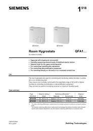
AccessoriesDescriptionProduct no. / Datastock no. sheetChangeover mounting kit (50 pcs / package) ARG86.3 N3009Adapter plate 120 x 120 mm for 4“ x 4“N3009ARG70conduit boxesAdapter plate 112 x 130 mm for surface wiring ARG70.2 N3009<strong>KNX</strong> Power supply 160 mA (Siemens BT LV) 5WG1 125-1AB01 --<strong>KNX</strong> Power supply 320 mA (Siemens BT LV) 5WG1 125-1AB11 --<strong>KNX</strong> Power supply 640 mA (Siemens BT LV) 5WG1 125-1AB21 --Mechanical designThe room <strong>thermostat</strong> consists of 2 parts: Plastic housing <strong>with</strong> electronics, operating elements and room temperaturesensor Mounting plate <strong>with</strong> screw terminalsThe housing engages in the mounting plate and is secured <strong>with</strong> 2 screws.Operation and settings1231. Operating mode selector / Esc2. Protection and OK3. Rotary knob to adjust setpointsand parameters6 / 14Siemens <strong>RDG400KN</strong> <strong>Room</strong> <strong>thermostat</strong> <strong>with</strong> <strong>KNX</strong> <strong>communications</strong> CE1N3192enBuilding Technologies 01 Jun 2010
Display# Symbol Description # Symbol Description1 Heating mode 11 Confirmation of parameters2Heating mode,electric heater active12Degrees CelsiusDegrees Fahrenheit3 Cooling mode 13 Digits for room temperature and setpoint display4 Comfort 14 Button lock active5 Economy 15 Condensation in room (dewpoint sensor active)6Auto Timer mode according toschedule (via <strong>KNX</strong>)16Weekday 1…7 from <strong>KNX</strong> bus1 = Monday / 7 = Sunday7 Protection mode 17 Fault8 Escape 18Temporary timer function; visible whenoperating mode is temporarily extended(extended presence or absence)9Additional user information, like outdoortemperature or time of dayfrom <strong>KNX</strong> bus. Selectable via parameters19 Indicates that room temperature is displayed10Morning: 12-hour formatAfternoon: 12-hour format20Primary fan is active (only supported <strong>with</strong>Synco700 primary controller)Engineering notesSee the "Reference documentation", page 12 for information on how to engineerthe <strong>KNX</strong> bus (topology, bus repeaters, etc.) and how to select and dimensionconnecting cables for supply voltage and field devices.Siemens <strong>RDG400KN</strong> <strong>Room</strong> <strong>thermostat</strong> <strong>with</strong> <strong>KNX</strong> <strong>communications</strong> CE1N3192enBuilding Technologies 01 Jun 20107 / 14
Mounting and installationDo not mount on a wall in niches or bookshelves, behind curtains, above or nearheat sources, or exposed to direct solar radiation. Mount about 1.5 m above thefloor.Mounting Mount the room <strong>thermostat</strong> on a clean, dry indoor place <strong>with</strong>out direct airflowfrom a heating / cooling device, and not exposed to drips or splash water.WiringSee the mounting instructions M3192 enclosed <strong>with</strong> the <strong>thermostat</strong>. Comply <strong>with</strong> local regulations to wire, fuse and earth the <strong>thermostat</strong>. The power supply line must have an external fuse or circuit breaker <strong>with</strong> a ratedcurrent of no more than 10 A. Isolate the cables of inputs X1-M, U1-G0 and D1-GND for 230 V if the conduitbox carries AC 230 V mains voltage. Inputs X1-M or D1-GND: Several switches (e.g. summer/winter switch) may beconnected in parallel. Consider overall maximum contact sensing current forswitch rating. Isolate the cables of <strong>KNX</strong> communication input CE+ / CE- for 230 V if the conduitbox carries AC 230 V mains voltage. No cables provided <strong>with</strong> a metal sheath. Disconnect from supply before removing from the mounting plate.Commissioning notesApplicationsThe room <strong>thermostat</strong> is delivered <strong>with</strong> a fixed set of applications.Select and activate the relevant application during commissioning using one of thefollowing tools: Local DIP switch and HMI Synco ACS ETS3 Professional (planned)Set the DIP switches before snapping the <strong>thermostat</strong> to the mounting plate, If youwant to select an application via DIP switches,.All DIP switches need to be set to “OFF” ("remote configuration"), if you want toselect an application via commissioning tool.8 / 14Siemens <strong>RDG400KN</strong> <strong>Room</strong> <strong>thermostat</strong> <strong>with</strong> <strong>KNX</strong> <strong>communications</strong> CE1N3192enBuilding Technologies 01 Jun 2010
After power is applied, the <strong>thermostat</strong> resets and all LCD segments flash, indicatingthat the reset was correct. After the reset, which takes about 3 seconds, the<strong>thermostat</strong> is ready for commissioning by qualified HVAC staff.If all DIP switches are OFF, the display reads "NO APPL" to indicate that applicationcommissioning via a tool is required.NoteEach time the application is changed, the <strong>thermostat</strong> reloads the factory setting forall control parameters, except for <strong>KNX</strong> device and zone addresses!Connect toolConnect the Synco ACS or ETS3 Professional tools to the <strong>KNX</strong> bus cable at anypoint for commissioning:<strong>KNX</strong>GX1 M U1 D1 GND CE+ CE-<strong>KNX</strong>SiemensN148 /UP146 /UP152<strong>KNX</strong>SiemensOCI700G0 Y10 Y1 Y2N1V24USBRS232ETSETS / ACS3192A04ACS and ETS3 require an interface: RS232 <strong>KNX</strong> interface (e.g. Siemens N148 / UP146 / UP152) OCI700 USB-<strong>KNX</strong> interfaceNoteAn external <strong>KNX</strong> bus power supply is required if an <strong>RDG400KN</strong> is connecteddirectly to a tool (ACS or ETS3) via <strong>KNX</strong> interface.Control parametersControl sequenceCalibrate sensorSetpoint and setpointrange limitationThe <strong>thermostat</strong>'s control parameters can be set to ensure optimum performance ofthe entire system (see basic documentation P3192).The parameters can be adjusted using Local HMI Synco ACS ETS3 Professional (planned) The control sequence may need to be set via parameter P01 depending on theapplication. The factory setting is “Cooling only” Recalibrate the temperature sensor if the room temperature displayed on the<strong>thermostat</strong> does not match the room temperature measured (after min. 1 hour ofoperation). To do this, change parameter P05 We recommend to review the setpoints and setpoint ranges (parametersP08…P12) and change them as needed to achieve maximum comfort and saveenergySiemens <strong>RDG400KN</strong> <strong>Room</strong> <strong>thermostat</strong> <strong>with</strong> <strong>KNX</strong> <strong>communications</strong> CE1N3192enBuilding Technologies 01 Jun 20109 / 14
Programming modeThe programming mode helps identify the <strong>thermostat</strong> in the <strong>KNX</strong> network duringcommissioning.Press the left and right buttons simultaneously for 6 sec to activate programmingmode, which is indicated on the display <strong>with</strong> "PrOg".Programming mode remains active until the identification of the <strong>thermostat</strong> iscomplete.Assign <strong>KNX</strong> groupaddresses<strong>KNX</strong> serial NumberUse ETS3 Professional to assign the <strong>KNX</strong> group addresses of the RDG communicationobjects,.Each device has a unique <strong>KNX</strong> serial number inside of the plastic housing.An additional sticker <strong>with</strong> the same <strong>KNX</strong> serial number is enclosed in the packagingbox. This sticker is intended for installers for documentation purposes.DisposalThis device is classified as waste electronic equipment under European Directive2002/96/EC (WEEE) and may not be disposed of as unsorted municipal waste.Adhere to all relevant national laws.Regarding disposal, use the systems setup for collecting electronic waste.Observe all local and applicable laws.Technical dataPower supplyOutputsInputsOperating voltage SELV AC 24 V 20%Frequency50/60 HzPower consumptionMax. 2 VA / 1 WControl output Y10-G0ResolutionCurrentDC 0…10 V39 mVMax. 1 mAControl output Y1, Y2-GRatingAC 24 VMax. 1 AMultifunctional inputsX1-MTemperature sensor inputTypeDigital inputOperating actionContact sensingU1-G0Input for actual damper position feedbackdamper position 0% (fully closed)100% (fully open)D1-GNDOperating actionContact sensingFunction of inputsExternal temperature sensor, heating/coolingchangeover sensor, operating mode switchovercontact, dewpoint monitor contact, enableelectric heater contact, fault contact, monitoringinputQAH11.1 (NTC)Selectable (NO/NC)DC 0…5 V, max. 5 mADC 0…10 V, max 0.3 mA0…100%Selectable (NO/NC)SELV DC 6…15 V, 3…6 mASelectableX1: P38D1: P4210 / 14Siemens <strong>RDG400KN</strong> <strong>Room</strong> <strong>thermostat</strong> <strong>with</strong> <strong>KNX</strong> <strong>communications</strong> CE1N3192enBuilding Technologies 01 Jun 2010
<strong>KNX</strong> busOperational dataEnvironmental conditionsInterface type<strong>KNX</strong>, TP1-64(electrically isolated)Bus current20 mABus topology: See <strong>KNX</strong> manual (reference documentation, see below)Switching differential, adjustableHeating mode(P30) 2 K (0.5...6 K)Cooling mode(P31) 1 K (0.5...6 K)Setpoint setting and setpoint rangeComfort(P08) 21 °C (5…40 °C)Economy(P11-P12) 15 °C/30 °C (OFF, 5…40 °C)Protection(P65-P66) 8 °C/OFF (OFF, 5…40 °C)Multifunctional inputs X1 / D1Input X1 default valueSelectable (0...8)(P38) 1 (Ext. temperature sensor,room or return air)Input D1 default value(P42) 3 (Operating modeswitchover)Built-in room temperature sensorMeasuring rangeAccuracy at 25 °CTemperature calibration rangeSettings and display resolutionSetpointsCurrent temperature value displayedOperationClimatic conditionsTemperatureHumidityTransportClimatic conditionsTemperatureHumidityMechanical conditionsStorageClimatic conditionsTemperatureHumidity0…49 °C< ± 0.5 K± 3.0 K0.5 °C0.5 °CIEC 721-3-3Class 3K50...50 °C
Standards and directivesconformity to EMC directive2004/108/ECC-tick conformity to EMC emission standard AS/NZS 61000.6.3: 2007Reduction of hazardous substances2002/95/EGGeneralProduct standardsAutomatic electrical controls for household andsimilar useSpecial requirements for temperature-dependentcontrolsElectronic control typeEN 60730–1EN 60730–2-92.B (micro-disconnection onoperation)Home and Building Electronic SystemsEN 50090-2-2Electromagnetic compatibilityEmissions (residential)IEC/EN 61000-6-3Immunity (Industry and residential)IEC/EN 61000-6-2Safety class III as per EN 60730Pollution classNormalDegree of protection of housing IP30 as per EN 60529Connection terminalsHousing front colorWeight <strong>with</strong>out / <strong>with</strong> packagingSolid wires or strandedwires <strong>with</strong> wire end sleeves1 x 0.4…2.5 mm 2or 2 x 0.4…1.5 mm 2RAL 9003 white0.237 kg / 0.360 kgReference documentation Handbook for Home and Building Control - Basic Principles (www.knx.org/uk/newspress/publications/publications/)Synco CE1P3127 Communication via the <strong>KNX</strong> bus for Synco 700, 900 and RXB/RXLBasic documentationDESIGO CM1Y9775 DESIGO RXB integration – S-modeCM1Y9776 DESIGO RXB / RXL integration – individual addressingCM1Y9777 Third-party integrationCM1Y9778 Synco integrationCM1Y9779 Working <strong>with</strong> ETS12 / 14Siemens <strong>RDG400KN</strong> <strong>Room</strong> <strong>thermostat</strong> <strong>with</strong> <strong>KNX</strong> <strong>communications</strong> CE1N3192enBuilding Technologies 01 Jun 2010
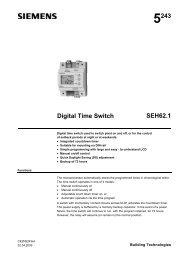
Connection terminalsG X1 MG0Y10U1D1 GNDY1Y2CE+ CE -3192A01SELVG, G0 Operating voltage AC 24 VY10/G0 Control output for DC 0…10 V actuatorY1/G, Y2/G Control output for 2-position, PWM or 3-positionactuatorsX1 Multifunctional input for temperature sensor (e.g.QAH11.1) or potential-free switchFactory setting: external temperature sensor(function can be selected via parameters P38)M Measuring neutral for sensors and switchesU1 DC 0…10 V input for actual damper position(Note: G0 is the measuring neutral for U1!)D1, GND Multifunctional input for potential-free switch.Factory setting: Operating mode switchovercontact(function can be selected via parameters P42)CE+ <strong>KNX</strong> data +CE- <strong>KNX</strong> data –Connection diagramsApplicationSingle ductSingle-duct <strong>with</strong>electric heater,radiator orheating / coolingvalveGF 10 AAC 24 VG0GG0<strong>KNX</strong>S1B1 r1S3X1 M U1 D1 GND CE+ CE-Y10 Y1 Y2N1V11 mA max.V11 A max.V1 V21 mA max.1 A max.3192A02N1V1V2S1r1S3B1<strong>Room</strong> <strong>thermostat</strong> <strong>RDG400KN</strong>Damper actuator or VAV compact controller:DC 0…10 V or 3-positionElectric heater, radiatoror heating / cooling valve:DC 0…10 V, 2-position, PWM or 3-positionSwitch (keycard, window contact, etc.)Feedback signal for actual damper positionSwitch at SELV input(keycard, window contact)Temperature sensor (return air temperature,external room temperature, changeoversensor, etc.)CE+ <strong>KNX</strong> data +CE- <strong>KNX</strong> data –V2V11 A max.13 / 14Siemens <strong>RDG400KN</strong> <strong>Room</strong> <strong>thermostat</strong> <strong>with</strong> <strong>KNX</strong> <strong>communications</strong> CE1N3192enBuilding Technologies 01 Jun 2010
DimensionsDimensions in mm4.09.028.328.34.028.328.3128.028.316.027.793.028.530.828.2 27.814 / 14 2010 Siemens Switzerland LtdSubject to changeSiemens <strong>RDG400KN</strong> <strong>Room</strong> <strong>thermostat</strong> <strong>with</strong> <strong>KNX</strong> <strong>communications</strong> CE1N3192enBuilding Technologies 01 Jun 2010